CN214603419U - Grinding machine is used in production of adjustable diamond saw bit - Google Patents
Grinding machine is used in production of adjustable diamond saw bit Download PDFInfo
- Publication number
- CN214603419U CN214603419U CN202120976354.5U CN202120976354U CN214603419U CN 214603419 U CN214603419 U CN 214603419U CN 202120976354 U CN202120976354 U CN 202120976354U CN 214603419 U CN214603419 U CN 214603419U
- Authority
- CN
- China
- Prior art keywords
- grinding wheel
- saw blade
- support
- grinding
- motor
- Prior art date
- Legal status (The legal status is an assumption and is not a legal conclusion. Google has not performed a legal analysis and makes no representation as to the accuracy of the status listed.)
- Active
Links
Images


Landscapes
- Finish Polishing, Edge Sharpening, And Grinding By Specific Grinding Devices (AREA)
Abstract
The application relates to a grinding machine for producing an adjustable diamond saw blade, which belongs to the technical field of saw blade processing and comprises a workbench, wherein a movable block is arranged on the upper surface of the workbench, a support is hinged to the movable block, the hinge axis of the support is horizontally arranged, a grinding wheel spindle is rotatably connected to the support and is arranged in parallel to the hinge axis of the support, a grinding wheel is fixedly arranged at one end of the grinding wheel spindle, and a driving mechanism for driving the grinding wheel spindle to rotate is arranged on the support; the upper surface of the workbench is provided with a moving mechanism for the moving block to move horizontally; the worktable is provided with a rotating mechanism for the saw blade to rotate. This application has can enough polish to the top sword of saw bit, can polish to the side sword of saw bit again to improve the effect of the efficiency of polishing of saw bit.
Description
Technical Field
The application relates to the technical field of saw blade processing, in particular to an adjustable grinding machine for diamond saw blade production.
Background
Saw blades are a general term for thin circular cutters used to cut solid materials. The saw blade can be divided into: diamond saw blade, high-speed steel saw blade, hard alloy saw blade. The new saw blade needs to be ground by a grinding machine before use, and the grinding machine is a machine tool for grinding the surface of a workpiece by using a grinding tool.
In the related art, a grinding machine comprises a workbench, a support is arranged on the workbench, the support is hinged on the workbench, and a grinding wheel and a motor for driving the grinding wheel to rotate are arranged on the support; the worktable is also provided with a rotating mechanism for fixing the saw blade; when the grinding machine processes a workpiece, the grinding wheel can move up and down to grind the side edge of the saw blade.
In view of the above-mentioned related technologies, the inventor believes that there is a defect that when a workpiece is machined by a grinding machine, a grinding wheel can only grind a side edge of the workpiece, but cannot grind a top edge of the workpiece, resulting in low grinding efficiency.
SUMMERY OF THE UTILITY MODEL
In order to make the grinding machine add man-hour, can enough polish the top sword of saw bit, can polish the side sword of saw bit again to improve the efficiency of polishing of saw bit, this application provides an adjustable grinding machine for diamond saw bit production.
The application provides a grinding machine is used in production of adjustable diamond saw blade adopts following technical scheme:
a grinding machine for producing an adjustable diamond saw blade comprises a workbench, wherein a movable block is arranged on the upper surface of the workbench, a support is hinged to the movable block, the hinge axis of the support is horizontally arranged, a grinding wheel spindle is connected to the support in a rotating mode and is parallel to the hinge axis of the support, a grinding wheel is fixedly arranged at one end of the grinding wheel spindle, and a driving mechanism for driving the grinding wheel spindle to rotate is arranged on the support; the upper surface of the workbench is provided with a moving mechanism for the moving block to move horizontally; the worktable is provided with a rotating mechanism for the saw blade to rotate.
By adopting the technical scheme, when the side edge of the saw blade is polished, the saw blade is fixedly arranged on the rotating mechanism, and the rotating mechanism drives the saw blade to rotate; the grinding wheel is driven to move up and down by rotating the bracket, the circumferential side wall of the grinding wheel is contacted with the side edge of the saw blade, and the moving mechanism drives the moving block to move horizontally until the side edge is polished; the moving mechanism continuously drives the moving block to move, so that the grinding wheel is contacted with the top edge of the saw blade, the bracket is rotated, the grinding wheel moves up and down, and the top edge is ground by the grinding wheel; in the polishing process, the grinding machine can polish the side edge of the saw blade and also can polish the top edge of the saw blade, so that the polishing efficiency is improved.
Optionally, the moving mechanism includes a first motor, two panels, a screw rod and a guide pipe, the two panels are vertically and fixedly arranged on the upper surface of the workbench, the screw rod is rotatably connected between the two panels, the screw rod is horizontally arranged, one end of the screw rod is fixedly connected with the first motor, and the first motor is fixedly arranged on the panels; the guide tube is horizontally arranged between the two panels, the axis of the guide tube is parallel to the axis of the lead screw, and the moving block is provided with a through hole for the guide tube to penetrate through; the moving block is in threaded connection with the lead screw.
By adopting the technical scheme, the two face plates have the bearing effect on the lead screw and the guide pipe, the first motor is started, the lead screw is driven by the first motor to rotate, and the lead screw rotates to drive the moving block to horizontally move along the axis direction of the lead screw, so that the moving efficiency and the moving stability of the moving block are improved.
Optionally, the number of the guide pipes is two, the number of the through holes is two, the two guide pipes are symmetrically arranged on two sides of the screw rod, axes of the two guide pipes are parallel to an axis of the screw rod, and the two guide pipes penetrate through the two through holes respectively.
Through adopting above-mentioned technical scheme, when the lead screw rotated, reduce because the lead screw rotates the possibility that drives the movable block pivoted, the stand pipe was injectd the movable block position, and is more steady when making the movable block move along the lead screw axis.
Optionally, the driving mechanism includes a second motor, a driving wheel, a driven wheel and a belt, an output shaft of the second motor is fixedly connected with the driving wheel, one end of the grinding wheel shaft, which is far away from the grinding wheel, is fixedly connected with the driven wheel, a rotating shaft of the driving wheel is parallel to a rotating shaft of the support, a rotating shaft of the driven wheel is parallel to a rotating shaft of the driving wheel, and the belt is sleeved between the driving wheel and the driven wheel.
Through adopting above-mentioned technical scheme, start the second motor and make the action wheel rotate, the action wheel passes through the belt and drives from the driving wheel rotation to the grinding wheel that the drive links firmly at emery wheel axle head portion rotates, has improved the rotation efficiency of grinding wheel.
Optionally, a hydraulic cylinder is arranged on the lower surface of the support, the top end of the hydraulic cylinder is hinged to the support, and a hinge axis of the top end of the hydraulic cylinder is parallel to a hinge axis of the support; the bottom end of the hydraulic cylinder is hinged with a bearing plate, and the hinge axis of the bottom end of the hydraulic cylinder is parallel to the hinge axis of the bracket; the side of loading board and movable block links firmly.
Through adopting above-mentioned technical scheme, the pneumatic cylinder pushes away and makes the support rotate, and the support rotates around self articulated axis, has reached and has used manpower sparingly, improves the effect of the efficiency of polishing.
Optionally, the rotating mechanism includes a third motor, a rotating shaft, a rotating disc, and a positioning column; the workstation lower surface sets firmly bears the box, and the third motor sets firmly bears the box inner bottom surface, and the third motor sets firmly with the axis of rotation is coaxial, the vertical setting of axis of rotation, and the top and the rotary disk of axis of rotation link firmly, and the rotary disk upper surface sets firmly the reference column, and fixed surface inlays and is equipped with a plurality of magnets on the rotary disk.
By adopting the technical scheme, the saw blade is sleeved on the positioning column, and the magnet attracts and fixes the saw blade; starting a third motor, wherein an output shaft of the third motor drives a rotating shaft to rotate, so that the upper surface of a rotating disc is driven to attract and fix a saw blade to rotate; the saw blade is fast and simple to install, the installation time is saved, and the working efficiency is improved.
Optionally, a bolt is arranged between the positioning column and the rotating disc, and the bottom end of the bolt penetrates through the positioning column and continues to extend downwards into the rotating disc and then is in threaded connection with the rotating disc.
By adopting the technical scheme, saw blades of different specifications are processed, the diameters of the required positioning columns are different, and the positioning columns with different diameters are replaced to adapt to the saw blades of different specifications; when the positioning column is replaced, the bolt is screwed until the bolt is separated from the rotating disc, at the moment, the positioning column can be taken down from the rotating disc, the positioning column with the required diameter is selected, the bolt penetrates through the selected positioning column, and the bolt is screwed until the bolt is screwed on the rotating disc, so that the utilization rate of the grinding machine is higher.
Optionally, the diameter of the rotating disc is smaller than the diameter of the saw blade.
By adopting the technical scheme, the diameter of the rotating disk is smaller than that of the processed saw blade, so that the saw blade fixed on the rotating mechanism is easier to take down.
Optionally, a fixing plate is fixedly arranged on the circumferential side wall of the grinding wheel shaft, a nut is connected to the grinding wheel shaft through a thread, the grinding wheel is sleeved between the fixing plate and the nut, and the nut tightly pushes the grinding wheel against the fixing plate.
By adopting the technical scheme, the nut can be unscrewed from the grinding wheel shaft, the grinding wheel can be taken down, a new grinding wheel is sleeved on the grinding wheel shaft, the nut is screwed on the grinding wheel shaft again until the nut tightly pushes the grinding wheel on the fixing plate, and the grinding efficiency of the grinding wheel is improved.
In summary, the present application includes at least one of the following beneficial technical effects:
1. when the saw blade is ground, the moving mechanism pushes the moving block to move horizontally, so that the support moves horizontally in the moving direction of the moving block, the grinding wheel is finally driven to move, and the hydraulic cylinder on the moving block pushes the support to rotate, so that the grinding wheel moves vertically; the rotating mechanism drives the saw blade fixed on the rotating disk to rotate; the flexible movement of the grinding wheel is realized, and the position of the grinding wheel is adjusted to realize the grinding of the side edge and the top edge of the saw blade;
2. the positioning columns can be detached from the rotating disc to replace positioning columns with different diameters, so that positioning machining of saw blades with different specifications is realized, and the utilization rate of a grinding machine is improved;
3. through setting up two stand pipes in lead screw bilateral symmetry, when the lead screw rotated, reduced the movable block and driven pivoted possibility by the lead screw, realized that the movable block steadily slided along lead screw axis direction.
Drawings
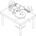
FIG. 1 is a schematic structural diagram of an embodiment of the present application;
FIG. 2 is a schematic view showing the structure of a moving block;
FIG. 3 is a schematic view showing the structure of the grinding wheel;
fig. 4 is a schematic view showing the structure of the rotating mechanism.
In the figure, 1, a workbench; 11. a carrying box; 2. a moving mechanism; 21. a first motor; 22. a panel; 23. a lead screw; 24. a guide tube; 3. a support; 4. a drive mechanism; 41. a second motor; 42. a driving wheel; 43. a driven wheel; 44. a belt; 5. a rotation mechanism; 51. a third motor; 52. a rotating shaft; 53. rotating the disc; 531. a magnet; 54. a positioning column; 541. a bolt; 6. a moving block; 61. a through hole; 62. a carrier plate; 7. a grinding wheel spindle; 71. a fixing plate; 72. grinding a grinding wheel; 73. a nut; 8. and a hydraulic cylinder.
Detailed Description
The present application is described in further detail below with reference to figures 1-4.
The embodiment of the application discloses adjustable diamond saw blade production is with grinding machine.
Referring to fig. 1 and 2, the grinding machine for producing the adjustable diamond saw blade comprises a workbench 1, wherein a moving mechanism 2, a driving mechanism 4 and a rotating mechanism 5 are arranged on the workbench 1; the lower surface of the workbench 1 is fixedly provided with a bearing box 11, the rotating mechanism 5 is arranged in the bearing box 11, and the rotating mechanism 5 drives a saw blade horizontally arranged above the workbench 1 to rotate; the moving mechanism 2 is provided with a moving block 6, the moving mechanism 2 is used for driving the moving block 6 to move horizontally, and the upper surface of the moving block 6 is hinged with a support 3; the driving mechanism 4 is arranged on the upper surface of the bracket 3, the upper surface of the bracket 3 is rotationally connected with the grinding wheel shaft 7, the driving mechanism 4 drives the grinding wheel shaft 7 to rotate, and the grinding wheel 72 is fixedly arranged on the grinding wheel shaft 7; a bearing plate 62 is fixedly connected to one side face of the moving block 6, a hydraulic cylinder 8 is arranged on the upper surface of the bearing plate 62, the bottom end of the hydraulic cylinder 8 is rotatably connected to the upper surface of the bearing plate 62, a rotating shaft at the bottom end of the hydraulic cylinder 8 is parallel to a rotating shaft of the support 3, the top end of the hydraulic cylinder 8 is rotatably connected with the support 3, and the rotating shaft at the top end of the hydraulic cylinder 8 is parallel to a rotating shaft of the support 3.
The rotating mechanism 5 drives the saw blade to rotate, the driving mechanism 4 drives the grinding wheel shaft 7 to rotate, and then the grinding wheel 72 rotates; the hydraulic cylinder 8 pushes the bracket 3 to rotate around the rotating shaft of the bracket 3, so that the grinding wheel 72 moves up and down, and the side edge of the saw blade is ground; the moving mechanism 2 drives the moving block 6 to move horizontally, so that the grinding wheel shaft 7 rotationally connected with the upper surface of the support 3 is driven to move, the hydraulic cylinder 8 drives the support 3 to rotate, the grinding wheel 72 moves downwards, the grinding wheel 72 is in contact with the top blade, the top blade is ground, and the grinding efficiency of the grinding machine is improved.
Referring to fig. 1 and 2, the moving mechanism 2 includes a first motor 21, two panels 22, a lead screw 23, and a guide pipe 24, the two panels 22 are vertically and fixedly arranged on the workbench 1, the lead screw 23 is rotatably connected with the two panels 22, one end of the lead screw 23 is fixedly connected with the first motor 21, and the first motor 21 is fixed on the panels 22; the moving block 6 is in threaded connection with the lead screw 23, two through holes 61 are formed in the moving block 6, and the two through holes 61 are symmetrically arranged on two sides of the threaded connection; two stand pipes 24 are fixed to be set up between two panels 22, and two stand pipes 24 are all parallel with lead screw 23, and two stand pipes 24 run through two through-holes 61 respectively, and two stand pipes 24 symmetry set up in lead screw 23 both sides.
The first motor 21 is started, the output shaft of the first motor 21 drives the lead screw 23 to rotate, the lead screw 23 drives the moving block 6 in threaded connection to do linear motion along the axis direction of the lead screw 23, and the two guide pipes 24 can reduce the possibility that the lead screw 23 drives the moving block 6 to rotate, so that the moving block 6 is more stable when moving.
Referring to fig. 1 and 3, the driving mechanism 4 includes a second motor 41, a driving wheel 42, a driven wheel 43, and a belt 44, the second motor 41 is fixedly connected to the bracket 3, and an output shaft of the second motor 41 is fixedly connected to the driving wheel 42; the driven wheel 43 is fixedly arranged on the circumferential side wall of one end of the grinding wheel shaft 7 far away from the rotating mechanism 5, and the belt 44 is sleeved between the driving wheel 42 and the driven wheel 43; a nut 73, a grinding wheel 72 and a fixing plate 71 are arranged on the circumferential side wall of one end, close to the rotating mechanism 5, of the grinding wheel shaft 7, the nut 73 is in threaded connection with the grinding wheel shaft 7, the fixing plate 71 is fixedly arranged on the grinding wheel shaft 7, the grinding wheel 72 is sleeved on the grinding wheel shaft 7, and the grinding wheel 72 is located between the fixing plate 71 and the nut 73; the nut 73 is tightened until it pushes the grinding wheel 72 and the fixed plate 71 tightly.
Screwing the nut 73 until the nut 73 is separated from the grinding wheel shaft 7, taking down the grinding wheel 72 to replace the new grinding wheel 72, sleeving the new grinding wheel 72 on the grinding wheel shaft 7, screwing the nut 73 on the grinding wheel shaft 7, realizing the replacement of the grinding wheel 72 and improving the grinding efficiency; the second motor 41 is started, the output shaft of the second motor 41 drives the driving wheel 42 to rotate, the driving wheel 42 drives the grinding wheel shaft 7 fixedly arranged on the driven wheel 43 to rotate through the belt 44, and finally the grinding wheel 72 is driven to rotate, so that the rotating efficiency of the grinding wheel 72 is improved.
Referring to fig. 4, the rotating mechanism 5 includes a third motor 51, a rotating shaft 52, a rotating disk 53, and a positioning post 54; the third motor 51 is fixedly connected with the inner bottom surface of the bearing box 11, and the third motor 51 is coaxially and fixedly connected with a rotating shaft 52 which is vertically arranged; the top ends of the rotating disc 53 and the rotating shaft 52 are fixedly connected, the rotating disc 53 is horizontally arranged, the diameter of the rotating disc 53 is smaller than that of any saw blade to be processed, a plurality of magnets 531 are fixedly embedded on the upper surface of the rotating disc 53, the positioning column 54 is fixedly connected to the center of the upper surface of the rotating disc 53, a bolt 541 is arranged between the positioning column 54 and the rotating disc 53, the bolt 541 penetrates through the positioning column 54, and the bottom end of the bolt 541 is in threaded connection with the inside of the rotating disc 53.
When the saw blade is polished, the saw blade is sleeved on the positioning column 54, the magnet 531 attracts the saw blade, the positioning column 54 positions the saw blade, and the magnet 531 fixes the saw blade; an output shaft of the third motor 51 drives the rotating shaft 52 to rotate, so as to drive the rotating disc 53 to rotate, and further drive the saw blade fixed on the rotating disc 53 to rotate; when the positioning column 54 is disassembled, the bolts 541 are screwed until the bolts 541 are separated from the rotating disc 53, at this time, the positioning column 54 can be taken down from the rotating disc 53, the standby positioning columns 54 with different diameters are selected, the bolts 541 penetrate through the selected positioning column 54, the bolts 541 are screwed into the rotating disc 53 again, and the positioning columns 54 are replaced, so that saw blades with different specifications are mounted in a suitable mode, and the utilization rate of the grinding machine is improved.
The implementation principle of the grinding machine for producing the adjustable diamond saw blade in the embodiment of the application is as follows: when the saw blade is polished, the saw blade to be processed is fixedly arranged on the rotating disc 53, the third motor 51 is started, the third motor 51 drives the rotating disc 53 fixedly arranged at the top end of the rotating shaft 52 to rotate, and the rotating disc 53 drives the saw blade fixedly arranged on the upper surface of the rotating disc 53 to rotate; starting the second motor 41, the second motor 41 drives the driving wheel 42 to rotate, the driving wheel 42 drives the driven wheel 43 to rotate through the belt 44, and the driven wheel 43 drives the grinding wheel 72 fixedly arranged on the circumferential side wall of the grinding wheel shaft 7 to rotate; starting the first motor 21, wherein the first motor 21 drives the lead screw 23 to rotate, the lead screw 23 drives the moving block 6 in threaded connection with the lead screw 23 to move, the moving block 6 drives the grinding wheel shaft 7 rotationally connected with the upper surface of the bracket 3 to move, and the grinding wheel shaft 7 drives the grinding wheel 72 to move; the moving block 6 also drives the hydraulic cylinder 8 rotationally connected with the upper surface of the bearing plate 62 to move; according to the condition that the saw blade needs to be polished, the position of the moving block 6 is adjusted, the grinding wheel 72 is moved, the hydraulic cylinder 8 pushes the support 3 to rotate, the grinding wheel 72 is moved up and down, the grinding machine is more flexible to process, polishing of the side edge and the top edge of the saw blade is finally achieved, and polishing efficiency of the grinding machine is improved.
The embodiments of the present invention are preferred embodiments of the present application, and the scope of protection of the present application is not limited by the embodiments, so: all equivalent changes made according to the structure, shape and principle of the present application shall be covered by the protection scope of the present application.
Claims (9)
1. The utility model provides an adjustable diamond saw blade production is with grinding machine, includes workstation (1), its characterized in that: the grinding machine is characterized in that a moving block (6) is arranged on the upper surface of the workbench (1), a support (3) is hinged to the moving block (6), the hinge axis of the support (3) is horizontally arranged, a grinding wheel shaft (7) is rotatably connected to the support (3), the grinding wheel shaft (7) is arranged in parallel to the hinge axis of the support (3), a grinding wheel (72) is fixedly arranged at one end of the grinding wheel shaft (7), and a driving mechanism (4) for driving the grinding wheel shaft (7) to rotate is arranged on the support (3); the upper surface of the workbench (1) is provided with a moving mechanism (2) for the moving block (6) to move horizontally; the worktable (1) is provided with a rotating mechanism (5) for the saw blade to rotate.
2. The grinding machine for producing the adjustable diamond saw blade as claimed in claim 1, wherein: the moving mechanism (2) comprises a first motor (21), two panels (22), a lead screw (23) and a guide pipe (24), the two panels (22) are vertically and fixedly arranged on the upper surface of the workbench (1), the lead screw (23) is rotatably connected between the two panels (22), the lead screw (23) is horizontally arranged, one end of the lead screw (23) is fixedly connected with the first motor (21), and the first motor (21) is fixedly arranged on the panel (22); the guide pipe (24) is horizontally arranged between the two panels (22), the axis of the guide pipe (24) is parallel to the axis of the screw rod (23), and a through hole (61) for the guide pipe (24) to penetrate through is formed in the moving block (6); the moving block (6) is in threaded connection with the lead screw (23).
3. The grinding machine for producing the adjustable diamond saw blade as claimed in claim 2, wherein: the guide pipes (24) are arranged in two numbers, the through holes (61) are formed in two numbers, the two guide pipes (24) are symmetrically arranged on two sides of the screw rod (23), the axes of the two guide pipes (24) are parallel to the axis of the screw rod (23), and the two guide pipes (24) penetrate through the two through holes (61) respectively.
4. The grinding machine for producing the adjustable diamond saw blade as claimed in claim 1, wherein: the driving mechanism (4) comprises a second motor (41), a driving wheel (42), a driven wheel (43) and a belt (44), an output shaft of the second motor (41) is fixedly connected with the driving wheel (42), one end, far away from a grinding wheel (72), of a grinding wheel shaft (7) is fixedly connected with the driven wheel (43), a rotating shaft of the driving wheel (42) is parallel to a rotating shaft of the support (3), a rotating shaft of the driven wheel (43) is parallel to the rotating shaft of the driving wheel (42), and the belt (44) is sleeved between the driving wheel (42) and the driven wheel (43).
5. The grinding machine for producing the adjustable diamond saw blade as claimed in claim 1, wherein: the lower surface of the support (3) is provided with a hydraulic cylinder (8), the top end of the hydraulic cylinder (8) is hinged with the support (3), and the hinge axis of the top end of the hydraulic cylinder (8) is parallel to the hinge axis of the support (3); the bottom end of the hydraulic cylinder (8) is hinged with a bearing plate (62), and the hinge axis of the bottom end of the hydraulic cylinder (8) is parallel to the hinge axis of the bracket (3); the bearing plate (62) is fixedly connected with the side surface of the moving block (6).
6. The grinding machine for producing the adjustable diamond saw blade as claimed in claim 1, wherein: the rotating mechanism (5) comprises a third motor (51), a rotating shaft (52), a rotating disc (53) and a positioning column (54); the lower surface of the workbench (1) is fixedly provided with a bearing box (11), a third motor (51) is fixedly arranged on the inner bottom surface of the bearing box (11), the third motor (51) and a rotating shaft (52) are coaxially fixedly arranged, the rotating shaft (52) is vertically arranged, the top end of the rotating shaft (52) is fixedly connected with a rotating disc (53), the upper surface of the rotating disc (53) is fixedly provided with a positioning column (54), and the upper surface of the rotating disc (53) is fixedly embedded with a plurality of magnets (531).
7. The grinding machine for producing the adjustable diamond saw blade as claimed in claim 6, wherein: a bolt (541) is arranged between the positioning column (54) and the rotating disk (53), the bottom end of the bolt (541) penetrates through the positioning column (54) and continues to extend downwards into the rotating disk (53) to be in threaded connection with the rotating disk (53).
8. The grinding machine for producing the adjustable diamond saw blade as claimed in claim 6, wherein: the diameter of the rotating disc (53) is smaller than that of the saw blade.
9. The grinding machine for producing the adjustable diamond saw blade as claimed in claim 1, wherein: the grinding wheel is characterized in that a fixing plate (71) is fixedly arranged on the circumferential side wall of the grinding wheel shaft (7), a nut (73) is connected to the grinding wheel shaft (7) in a threaded mode, the grinding wheel (72) is sleeved between the fixing plate (71) and the nut (73), and the nut (73) enables the grinding wheel (72) to be tightly pressed on the fixing plate (71).
Priority Applications (1)
| Application Number | Priority Date | Filing Date | Title |
|---|---|---|---|
| CN202120976354.5U CN214603419U (en) | 2021-05-08 | 2021-05-08 | Grinding machine is used in production of adjustable diamond saw bit |
Applications Claiming Priority (1)
| Application Number | Priority Date | Filing Date | Title |
|---|---|---|---|
| CN202120976354.5U CN214603419U (en) | 2021-05-08 | 2021-05-08 | Grinding machine is used in production of adjustable diamond saw bit |
Publications (1)
| Publication Number | Publication Date |
|---|---|
| CN214603419U true CN214603419U (en) | 2021-11-05 |
Family
ID=78407229
Family Applications (1)
| Application Number | Title | Priority Date | Filing Date |
|---|---|---|---|
| CN202120976354.5U Active CN214603419U (en) | 2021-05-08 | 2021-05-08 | Grinding machine is used in production of adjustable diamond saw bit |
Country Status (1)
| Country | Link |
|---|---|
| CN (1) | CN214603419U (en) |
Cited By (1)
| Publication number | Priority date | Publication date | Assignee | Title |
|---|---|---|---|---|
| CN115464481A (en) * | 2022-10-08 | 2022-12-13 | 绍兴广德幕墙有限公司 | Numerical control machine tool for polishing mullion of aluminum alloy window |
-
2021
- 2021-05-08 CN CN202120976354.5U patent/CN214603419U/en active Active
Cited By (2)
| Publication number | Priority date | Publication date | Assignee | Title |
|---|---|---|---|---|
| CN115464481A (en) * | 2022-10-08 | 2022-12-13 | 绍兴广德幕墙有限公司 | Numerical control machine tool for polishing mullion of aluminum alloy window |
| CN115464481B (en) * | 2022-10-08 | 2024-02-02 | 绍兴广德幕墙有限公司 | Numerical control machine tool for polishing middle stile of aluminum alloy window |
Similar Documents
| Publication | Publication Date | Title |
|---|---|---|
| CN201366753Y (en) | Multi-knife head moving-shaft over-long and over-wide giant-stone multipurpose processing machine | |
| CN112658830B (en) | Polishing device with noise reduction function for machining | |
| CN217019662U (en) | Vertical cylindrical grinding machine for machining shaft workpieces | |
| CN111618670A (en) | Adjustable twist drill grinding device | |
| CN102152179B (en) | Mobile grinding machine for repair of taper hole of machine tool spindle | |
| CN214603419U (en) | Grinding machine is used in production of adjustable diamond saw bit | |
| CN216098172U (en) | Simple polishing and cutting integrated machine | |
| CN201136118Y (en) | Abrasive band polisher for steel tubes | |
| CN211387227U (en) | Rotary workbench for gear blank machining | |
| CN204325828U (en) | A kind of orbital sander | |
| CN113290279A (en) | Steel pipe radial orifice trimming chamfering device | |
| CN202479953U (en) | Flange plane grinding device | |
| CN112658944A (en) | Five-axis linkage polishing machine for gantry | |
| CN206748215U (en) | Radial drill for graphite cushion block | |
| CN212946565U (en) | Multi-station efficient milling machine | |
| CN213646175U (en) | Gear chamfering machining equipment | |
| CN221621823U (en) | Automatic polishing equipment | |
| CN220805761U (en) | Polishing device for screws | |
| CN219293614U (en) | Multi-angle grinding wheel saw bench | |
| CN219944827U (en) | Electromechanical spare part processing cutting machine | |
| CN220481234U (en) | Grinding machine | |
| CN215921724U (en) | Multi-dimensional engraving and milling machine | |
| CN220362379U (en) | Precision grinding machine | |
| CN220839656U (en) | Hand-operated grinder clamping base structure | |
| CN215748159U (en) | Cutter polishing device |
Legal Events
| Date | Code | Title | Description |
|---|---|---|---|
| GR01 | Patent grant | ||
| GR01 | Patent grant |