CN214589162U - Electric device - Google Patents
Electric device Download PDFInfo
- Publication number
- CN214589162U CN214589162U CN202120944288.3U CN202120944288U CN214589162U CN 214589162 U CN214589162 U CN 214589162U CN 202120944288 U CN202120944288 U CN 202120944288U CN 214589162 U CN214589162 U CN 214589162U
- Authority
- CN
- China
- Prior art keywords
- pad
- battery
- board
- battery protection
- mainboard
- Prior art date
- Legal status (The legal status is an assumption and is not a legal conclusion. Google has not performed a legal analysis and makes no representation as to the accuracy of the status listed.)
- Active
Links
Images


Classifications
-
- Y—GENERAL TAGGING OF NEW TECHNOLOGICAL DEVELOPMENTS; GENERAL TAGGING OF CROSS-SECTIONAL TECHNOLOGIES SPANNING OVER SEVERAL SECTIONS OF THE IPC; TECHNICAL SUBJECTS COVERED BY FORMER USPC CROSS-REFERENCE ART COLLECTIONS [XRACs] AND DIGESTS
- Y02—TECHNOLOGIES OR APPLICATIONS FOR MITIGATION OR ADAPTATION AGAINST CLIMATE CHANGE
- Y02E—REDUCTION OF GREENHOUSE GAS [GHG] EMISSIONS, RELATED TO ENERGY GENERATION, TRANSMISSION OR DISTRIBUTION
- Y02E60/00—Enabling technologies; Technologies with a potential or indirect contribution to GHG emissions mitigation
- Y02E60/10—Energy storage using batteries
Landscapes
- Battery Mounting, Suspending (AREA)
- Connection Of Batteries Or Terminals (AREA)
Abstract
The utility model provides an electric device, includes battery and mainboard, and the battery includes the battery protection shield, is equipped with first pad on the battery protection shield, is equipped with the second pad on the mainboard, first pad and second pad welded connection to realize the electricity of battery protection shield and mainboard and be connected. The electric device is connected with the second pad of the mainboard in a welding mode through the first pad of the battery protection plate, so that the battery and the mainboard are electrically connected, the purpose of saving cost is achieved, contact impedance is eliminated, battery capacity loss is reduced, and the purpose of improving battery capacity is achieved.
Description
Technical Field
The present application relates to an electric device.
Background
In current electric devices, the outgoing line connection mode of the battery generally needs to be connected to the motherboard through a connector, and the connector is generally divided into a terminal connector and a board-to-board connector. The common terminal wire connector outlet method needs to combine the connector and the terminal wire together and then weld the terminal wire and the battery protection board together. The common wire outlet mode of the board-to-board connector needs to patch the board-to-board connector on the flexible circuit board and then weld the flexible circuit board and the battery protection board together. Both connectors require the motherboard to have corresponding male and female connectors to be able to snap together.
The board needs independent flexible circuit board carrier to be connected with the battery protection shield to the board connector, and the terminal line connector needs the wire carrier to be connected with the battery protection shield, leads to the cost of two kinds of connectors higher, and two kinds of connectors all have certain contact impedance simultaneously, increase the internal resistance of battery, lead to the inside loss capacity of battery to battery capacity has been reduced.
SUMMERY OF THE UTILITY MODEL
In view of the above, it is desirable to provide an electric device capable of reducing cost and increasing battery capacity.
An embodiment of the application provides an electric installation, including battery and mainboard, the battery includes the battery protection shield, be equipped with first pad on the battery protection shield, be equipped with the second pad on the mainboard, first pad with second pad welded connection, in order to realize the battery protection shield with the electricity of mainboard is connected.
The electric device is connected with the second pad of the mainboard in a welding mode through the first pad of the battery protection plate, so that the battery and the mainboard are electrically connected, a connector is not needed, the whole size is reduced, the purposes of saving cost and improving battery capacity are achieved, contact impedance is eliminated, battery capacity loss is reduced, and the purpose of improving battery endurance is achieved.
In some embodiments, the battery protection board includes a first main body portion and a first extending portion connected to each other, the first extending portion extends out of the first main body portion toward the main board, and the first pad is disposed on the first extending portion, so that the first pad is soldered to the second pad, and the battery protection board is prevented from interfering with the main board.
In some embodiments, the main board includes a second main body portion and a second extending portion connected to each other, the second extending portion extends out of the second main body portion toward the battery protection board, and the second pad is disposed on the second extending portion, so that the second pad is soldered to the first pad, and the battery protection board is prevented from interfering with the main board.
In some embodiments, the power device further comprises a fuse for connecting the first pad and the second pad after thermocompression.
In some embodiments, each second pad is provided with two parallel holes, and a part of the fusing part is located in the two holes, so that the connection between the first pad and the second pad is firmer, the contact area between the fusing part and the second pad is increased, the contact impedance is reduced, and the battery capacity loss is reduced.
In some embodiments, the main board is provided with a plurality of second pads, and an arrangement direction of the plurality of second pads is perpendicular to an arrangement direction of the holes, so that the structure is more compact.
In some embodiments, the battery protection board is one of a rigid circuit board or a flexible circuit board to accommodate various configurations of powered devices.
In some embodiments, the motherboard is one of a rigid circuit board or a flexible circuit board to accommodate multiple configurations of electrical devices.
In some embodiments, the melting piece is tin, so that the melting fluidity of the melting piece is better, the combination with other metals such as copper, aluminum and nickel is more convenient, and the conductivity can be improved.
In some embodiments, the battery protection board is provided with at least two first pads arranged in parallel, the main board is provided with the second pads, the number of the second pads is the same as that of the first pads, and each first pad corresponds to each second pad in a one-to-one manner, so that the battery protection board and the main board are ensured to be provided with a positive pad and a negative pad respectively.
Drawings
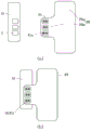
Fig. 1 is a schematic structural diagram of a battery protection board and a main board according to an embodiment of the present application.
Fig. 2 is a schematic structural diagram illustrating a connection between a battery cell, a battery protection board and a motherboard in an embodiment of the present application.
Fig. 3 is a schematic structural diagram of a battery protection board and a main board according to another embodiment of the present application.
Fig. 4 is a schematic structural diagram of a battery protection board and a main board according to still another embodiment of the present application.
Description of the main elements
Second body portion 20a
Hole 21a
Detailed Description
The technical solutions of the present application will be described below with reference to the accompanying drawings in the embodiments of the present application, and it is obvious that the described embodiments are only some embodiments of the present application, but not all embodiments.
It will be understood that when an element is referred to as being "secured to" another element, it can be directly on the other element or intervening elements may also be present. When a component is referred to as being "connected" to another component, it can be directly connected to the other component or intervening components may also be present. When a component is referred to as being "disposed on" another component, it can be directly on the other component or intervening components may also be present. The terms "vertical," "horizontal," "left," "right," and the like as used herein are for illustrative purposes only.
Unless defined otherwise, all technical and scientific terms used herein have the same meaning as commonly understood by one of ordinary skill in the art to which this application belongs. The terminology used herein in the description of the present application is for the purpose of describing particular embodiments only and is not intended to be limiting of the application. As used herein, the term "or/and" includes any and all combinations of one or more of the associated listed items.
An embodiment of the application provides an electric installation, including battery and mainboard, the battery includes the battery protection shield, be equipped with first pad on the battery protection shield, be equipped with the second pad on the mainboard, first pad with second pad welded connection, in order to realize the battery protection shield with the electricity of mainboard is connected.
The electric device is connected with the second pad of the mainboard in a welding mode through the first pad of the battery protection plate, so that the battery and the mainboard are electrically connected, a connector is not needed, the whole size is reduced, the purposes of saving cost and improving battery capacity are achieved, contact impedance is eliminated, battery capacity loss is reduced, and the purpose of improving battery endurance is achieved.
Some embodiments of the present application will be described in detail below with reference to the accompanying drawings. In the following embodiments, features of the embodiments may be combined with each other without conflict.
Referring to fig. 1, an embodiment of the present application provides an electric device 100, which includes a battery, the battery includes a battery protection board 10, the electric device 100 further includes a motherboard 20, and the battery is electrically connected to the motherboard 20 through the battery protection board 10 and supplies power to the motherboard 20. The battery protection plate 10 is provided with first pads 11. The main board 20 is provided with a second pad 21. The first bonding pad 11 and the second bonding pad 21 are connected by welding, so that the battery protection board 10 is electrically connected with the main board 20, the contact impedance between the battery protection board 10 and the main board 20 is reduced, the cruising ability of the battery is improved, and the cost of the electric device 100 is saved.
Referring to fig. 2, as an exemplary example, the battery further includes a battery cell 30, the battery cell 30 is electrically connected to the battery protection board 10, and then the battery protection board 10 is electrically connected to the motherboard 20 to supply power to the motherboard 20.
Referring to fig. 1, in an embodiment, the battery protection plate 10 includes a first main body portion 10a and a first extending portion 10b connected to each other, and the main plate 20 is substantially rectangular, as shown in fig. 1 (a). The first extending portion 10b extends out of the first main body portion 10a toward the main board 20. The first pad 11 is provided on the first extension portion 10 b. The first extending portion 10b is used to extend the first land 11 out of the first main body portion 10a, so as to facilitate the first land 11 to be welded to the second land 21, and prevent the battery protection board 10 from interfering with the main board 20, as shown in fig. 1 (b).
Referring to fig. 3, in an embodiment, the main board 20 includes a second main portion 20a and a second extending portion 20b connected to each other, and the battery protection plate 10 is substantially rectangular, as shown in fig. 3 (a). The second extension portion 20b extends out of the second main body portion 20b toward the battery protection plate 10. The second pad 21 is provided on the second extension portion 20 b. The second extending portion 20b is used to extend the second land 21 out of the second main body portion 20a, thereby facilitating the welding of the second land 21 to the first land 11, and also preventing the battery protection board 10 from interfering with the main board 20, as shown in fig. 3 (b).
Referring to fig. 4, in an embodiment, the battery protection plate 10 includes a first main body portion 10a and a first extending portion 10b connected to each other, and the main plate 20 also includes a second main body portion 20a and a second extending portion 20b connected to each other. The first extension portion 10b extends out of the first main body portion 10a toward the main board 20, and the second extension portion 20b extends out of the second main body portion 20b toward the battery protection board 10. The first pad 11 is disposed on the first extension portion 10b, and the second pad 21 is disposed on the second extension portion 20 b. The first extension portion 10b and the second extension portion 20b can facilitate the welding of the first pad 11 and the second pad 21, and prevent the battery protection board 10 from interfering with the main board 20.
In an embodiment, the power device 100 further includes a fuse (not shown) for connecting the first pad 11 and the second pad 21. When the first bonding pad 11 and the second bonding pad 12 are connected through thermocompression bonding, and during thermocompression, the melting piece is located between the first bonding pad 11 and the second bonding pad 21, the melting piece is melted at high temperature, and the melting piece solidified after cooling can be electrically connected with the first bonding pad 11 and the second bonding pad 21, so that the battery protection board 10 and the main board 20 are electrically connected. By way of illustrative example, the melt is tin metal, which makes the melt more fluid, facilitates bonding with other metals such as copper, aluminum, nickel, and may improve electrical conductivity.
In one embodiment, the fuse is located on the first pad 11 and manages a certain thickness before soldering.
In an embodiment, in order to reinforce the connection between the battery protection plate 10 and the main board 20, the second pad 21 is provided with a hole 21a, and during the welding process, a partially melted melting piece can flow into the hole 21a or the overflow hole 21a, so that the cooled melting piece exists between the first pad 11 and the second pad 21, and also exists in the hole 21a or the surface of the second pad 21 away from the first pad 11, thereby making the connection between the first pad 11 and the second pad 21 more stable, increasing the contact area between the melting piece and the second pad 21, further increasing the conductive area between the first pad 11 and the second pad 21, reducing the contact impedance and reducing the battery capacity loss.
Referring to fig. 1 or fig. 3, in an embodiment, the first pad 11 and the second pad 21 are substantially rectangular. The battery protection plate 10 is provided with three first pads 11 arranged in parallel as a positive pad, a negative pad and a signal output pad of the battery, respectively. The main board 20 is provided with three second pads 21 arranged in parallel, each first pad 11 corresponds to each second pad 21 one by one, and each second pad 21 is provided with two parallel holes 21a along the long side direction. In order to make the structure more compact, the arrangement direction of the second pads 21 is perpendicular to the arrangement direction of the holes 21 a. In other embodiments, the first pads 11 and the second pads 21 may be provided in other numbers as required, but there are at least two pads respectively, so as to ensure that the battery protection board 10 and the main board 20 have one positive pad and one negative pad respectively.
In one embodiment, the battery protection board 10 is one of a rigid circuit board or a flexible circuit board. The main board 20 is one of a rigid circuit board or a flexible circuit board.
The electric device 100 is welded and connected with the main board 20 through the first bonding pad 11, the second bonding pad 21 and the melting piece, so that the battery is electrically connected with the main board 20, a connector is not needed, the whole size is reduced, the purposes of saving cost and improving battery capacity are achieved, meanwhile, contact impedance is eliminated, the battery capacity loss is reduced, and the purpose of improving the battery endurance is achieved.
In addition, those skilled in the art should recognize that the foregoing embodiments are illustrative only, and not limiting, and that appropriate changes and modifications to the foregoing embodiments may be made within the spirit and scope of the present disclosure.
Claims (10)
1. An electric device comprises a battery and a mainboard, wherein the battery comprises a battery protection plate;
a second bonding pad is arranged on the main board;
the first welding pad is connected with the second welding pad in a welding mode, so that the battery protection board is electrically connected with the main board.
2. The power utilization device of claim 1, wherein: the battery protection board comprises a first main body part and a first extension part which are connected, the first extension part extends out of the first main body part towards the mainboard, and the first pad is arranged on the first extension part.
3. The powered device of claim 1 or 2, wherein: the main board comprises a second main body part and a second extending part which are connected, the second extending part extends out of the second main body part towards the battery protection board, and the second pad is arranged on the second extending part.
4. The powered device of claim 1, further comprising a fuse connecting the first pad and the second pad.
5. The power utilization device of claim 4, wherein: each second welding disc is provided with two parallel holes, and part of the melting piece is positioned in the two holes.
6. The power utilization device of claim 5, wherein: the mainboard is provided with a plurality of second pads, and the arrangement direction of the second pads is perpendicular to the arrangement direction of the holes.
7. The power utilization device of claim 4, wherein: the melting piece is tin.
8. The power utilization device of claim 1, wherein: the battery protection board is one of a hard circuit board or a flexible circuit board.
9. The power utilization device of claim 1, wherein: the mainboard is one of a hard circuit board or a flexible circuit board.
10. The power utilization device of claim 1, wherein: the battery protection board is provided with at least two first bonding pads arranged in parallel, the mainboard is provided with second bonding pads the number of which is the same as that of the first bonding pads, and each first bonding pad corresponds to each second bonding pad in a one-to-one mode.
Priority Applications (1)
| Application Number | Priority Date | Filing Date | Title |
|---|---|---|---|
| CN202120944288.3U CN214589162U (en) | 2021-04-28 | 2021-04-28 | Electric device |
Applications Claiming Priority (1)
| Application Number | Priority Date | Filing Date | Title |
|---|---|---|---|
| CN202120944288.3U CN214589162U (en) | 2021-04-28 | 2021-04-28 | Electric device |
Publications (1)
| Publication Number | Publication Date |
|---|---|
| CN214589162U true CN214589162U (en) | 2021-11-02 |
Family
ID=78362019
Family Applications (1)
| Application Number | Title | Priority Date | Filing Date |
|---|---|---|---|
| CN202120944288.3U Active CN214589162U (en) | 2021-04-28 | 2021-04-28 | Electric device |
Country Status (1)
| Country | Link |
|---|---|
| CN (1) | CN214589162U (en) |
-
2021
- 2021-04-28 CN CN202120944288.3U patent/CN214589162U/en active Active
Similar Documents
| Publication | Publication Date | Title |
|---|---|---|
| CN110299479B (en) | Electronic device | |
| CN101044645B (en) | Electrode connector containing plate and battery module employed with the same | |
| CN209822766U (en) | Battery pack and output structure thereof | |
| CN209515796U (en) | Cell module encapsulation structure and mobile terminal | |
| CN213125974U (en) | Photovoltaic junction box and photovoltaic module | |
| CN214589162U (en) | Electric device | |
| CN211879491U (en) | Battery management electricity is connected module spare and battery management electricity with coupling assembling | |
| CN111446407A (en) | Adapter plate and battery pack | |
| WO2023216774A1 (en) | Battery and electronic device | |
| CN211743287U (en) | Adapter plate and battery pack | |
| CN211791434U (en) | Large-current photovoltaic junction box structure | |
| CN110311084B (en) | Battery cell structure and electronic product | |
| CN209786058U (en) | Battery pack, electric equipment and movable platform | |
| CN210379033U (en) | Power device connection structure | |
| CN212967941U (en) | Integrated FPC-PCB assembly, power battery and vehicle thereof | |
| CN101217853B (en) | A welding method of chip pin and metal terminals | |
| CN221598227U (en) | Soft board subassembly and battery protection shield | |
| CN221727381U (en) | Storage battery, main board and electronic equipment | |
| CN217445573U (en) | Lithium battery protection plate capable of passing large current | |
| CN218040863U (en) | Battery protection board and battery packaging structure | |
| CN220896900U (en) | Circuit module and electronic equipment | |
| CN220122062U (en) | Battery and electronic equipment | |
| CN218351670U (en) | Battery protection plate and battery | |
| CN211909301U (en) | Battery core assembling structure and battery | |
| CN221727378U (en) | Multipolar ear electric core, battery monomer and battery module |
Legal Events
| Date | Code | Title | Description |
|---|---|---|---|
| GR01 | Patent grant | ||
| GR01 | Patent grant |