CN214524752U - Magnetic suspension box feeding device for continuous box packing machine - Google Patents
Magnetic suspension box feeding device for continuous box packing machine Download PDFInfo
- Publication number
- CN214524752U CN214524752U CN202120203406.5U CN202120203406U CN214524752U CN 214524752 U CN214524752 U CN 214524752U CN 202120203406 U CN202120203406 U CN 202120203406U CN 214524752 U CN214524752 U CN 214524752U
- Authority
- CN
- China
- Prior art keywords
- box
- magnetic suspension
- track
- feeding device
- magnetic
- Prior art date
- Legal status (The legal status is an assumption and is not a legal conclusion. Google has not performed a legal analysis and makes no representation as to the accuracy of the status listed.)
- Active
Links
Images


Landscapes
- Container Filling Or Packaging Operations (AREA)
Abstract
The utility model discloses a magnetic suspension box feeding device for a continuous box packing machine, which comprises a pre-box-separating mechanism and a magnetic suspension mechanism, wherein the pre-box-separating mechanism separates boxes arranged side by side from each other; the magnetic suspension mechanism further straightens the boxes separated from each other at equal intervals, realizes constant-speed motion with the box packing machine and sends the boxes into the box loading mechanism; the magnetic suspension mechanism comprises a magnetic suspension track, magnetic suspension rotors arranged in pairs are arranged on the magnetic suspension track, and the magnetic suspension rotors run on the magnetic suspension track; the magnetic suspension rotor is provided with a clamp, and two clamps on the magnetic suspension rotor in pairs clamp the box to realize accurate positioning; the utility model discloses can effectively avoid the box wearing and tearing, avoid the card box phenomenon, improve and go up box efficiency.
Description
Technical Field
The utility model relates to a box-packed putting is advanced to magnetic suspension, specific theory relates to a box-packed putting is advanced to magnetic suspension for continuous box packing machine belongs to packing technical field.
Background
The beverage bottle need be rather than dress the box after the filling is accomplished, and traditional beverage bottle dress box process is accomplished by the manual work, transports the beverage bottle box packing carton respectively through transportation roller or conveyer belt, and the manual work of operative employee gets and puts the beverage bottle, puts into the packing carton with the beverage bottle, but this kind of mode inefficiency, for solving the defect that manual packaging is inefficiency, has appeared carrying out the cartoning machine of automatic packaging to the beverage bottle, and the cartoning machine divide into horizontal and vertical. In the technical field of box packing machines, a common box separating and loading mode is a double-spiral box loading mechanism in the box separating and loading mode, but the double-spiral box loading mechanism has the following problems in actual production:
1. the box is greatly abraded, and the appearance quality of the box is influenced;
2. the box is easy to clamp and the box loading efficiency is low;
3. the box type is single, can not satisfy the last box of multiple gear box.
In view of the above, the prior art is obviously inconvenient and disadvantageous in practical use, and needs to be improved.
SUMMERY OF THE UTILITY MODEL
The to-be-solved technical problem of the utility model is to above not enough, provide a continuous cartoning machine magnetic suspension advances box-packed putting, can effectively avoid the box wearing and tearing, avoid the card box phenomenon, improve and go up box efficiency.
For solving the technical problem, the utility model discloses a following technical scheme: a magnetic suspension box feeding device for a continuous box packing machine comprises a pre-box-separating mechanism and a magnetic suspension mechanism, wherein the pre-box-separating mechanism separates boxes arranged side by side from each other; the magnetic suspension mechanism further straightens the boxes separated from each other at equal intervals, realizes constant-speed motion with the box packing machine and sends the boxes into the box loading mechanism;
the magnetic suspension mechanism comprises a magnetic suspension track, magnetic suspension rotors arranged in pairs are arranged on the magnetic suspension track, and the magnetic suspension rotors run on the magnetic suspension track; the magnetic suspension rotor is provided with a clamp, and two clamps on the magnetic suspension rotor in pairs clamp the box to realize accurate positioning.
Further, the box pre-sorting mechanism comprises two synchronous belt assemblies and box conveying chain channels, and the two synchronous belt assemblies are symmetrically arranged on two sides of each box conveying chain channel.
Further, the box conveying chain channel and the box feeding chain channel are mutually connected and independently run, and the running speed of the box conveying chain channel is greater than that of the box feeding chain channel.
Furthermore, the magnetic suspension mechanism is arranged on the side part of the upper box chain path, and the upper box chain path is connected with the box conveying chain path and runs independently.
Further, the hold-in range subassembly includes the hold-in range, the hold-in range passes through the motor and drives around two belt pulley ring directions operation, the functioning speed of hold-in range is the same with the functioning speed of defeated box chain way, and the hold-in range is close to one side of defeated box chain way and is the same with the traffic direction of defeated box chain way.
Furthermore, the magnetic suspension track is an annular track, and comprises a straight section and 180-degree bent sections arranged at two ends of the straight section, wherein the straight section is parallel to the chain path of the upper box, and the 180-degree bent sections are tangent to the straight section.
Furthermore, the box feeding mechanism is arranged on the other side, opposite to the magnetic suspension mechanism, of the box feeding chain way, the box feeding mechanism comprises a plurality of groups of box blocking positioning plates which are arranged in pairs and run along the annular track, and the pitch between the box blocking positioning plates arranged in pairs is fixed.
Furthermore, the clamp is formed by embedding an elastic material in a light material.
The utility model adopts the above technical scheme after, compare with prior art, have following advantage:
the utility model discloses can effectively avoid the box wearing and tearing, avoid the card box phenomenon, improve and go up box efficiency.
The present invention will be described in detail with reference to the accompanying drawings and examples.
Drawings
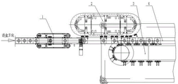
Fig. 1 is a schematic structural diagram of the present invention;
FIG. 2 is a schematic structural diagram of a pre-binning unit;
FIG. 3 is a schematic structural view of an upper cartridge unit;
FIG. 4 is a partial cross-sectional view of a magnetic levitation mechanism;
in the figure, the position of the upper end of the main shaft,
1-a pre-sorting box unit, 11-a box feeding chain channel, 12-a synchronous belt, 13-a box conveying chain channel, 2-a magnetic suspension mechanism, 21-a magnetic suspension track, 22-a magnetic suspension rotor, 23-a clamp, 3-a box loading mechanism, 31-a box blocking positioning plate and 4-a box loading chain channel.
Detailed Description
In order to clearly understand the technical features, objects, and effects of the present invention, embodiments of the present invention will be described with reference to the accompanying drawings.
Example 1
As shown in fig. 1-4 together, the utility model provides a continuous cartoning machine is with magnetic suspension box-entering device, including dividing box unit 1 and last box unit in advance, divide box unit 1 in advance including advancing box chain way 11 and dividing box mechanism in advance, divide box mechanism in advance to include synchronous belt subassembly 12 and defeated box chain way 13, defeated box chain way 13 links up each other and independent operation separately with advancing box chain way 11, the functioning speed of defeated box chain way 13 is greater than the functioning speed of advancing box chain way 11.
The number of the synchronous belt assemblies 12 is two, the two synchronous belt assemblies 12 are symmetrically arranged on two sides of the box conveying chain channel 13, each synchronous belt assembly 12 comprises a synchronous belt, the synchronous belts are driven by a motor to move around two belt pulleys in an annular mode, and the running speed of each synchronous belt is the same as that of the box conveying chain channel 13; and one side of the synchronous belt close to the box conveying chain channel 13 is the same as the running direction of the box conveying chain channel 13.
When the box is pre-divided, the empty boxes are arranged on the box feeding chain channel in the front-back direction of the moving direction, the empty boxes are driven to move forward sequentially by the box feeding chain channel, the empty boxes enter the box conveying chain channel through the box feeding chain channel and then are clamped and accelerated by the synchronous belt, the box is separated by a certain pitch due to the front-back speed difference, the box speed accelerated by clamping of the synchronous belt is the same as the speed of the box conveying chain channel, the bottom of the box is prevented from being damaged by friction, and the non-damage low-precision pre-dividing box is realized.
The box loading unit comprises a magnetic suspension mechanism, a box loading mechanism 3 and a box loading chain path 4, and the box loading chain path 4 is connected with the box conveying chain path 13 and runs independently; the magnetic suspension mechanism further arranges the separated boxes at equal intervals to realize constant-speed motion with the box packing machine, and the magnetic suspension mechanism is arranged on the side part of the upper box chain path 4. The magnetic suspension mechanism comprises a magnetic suspension track 21, the magnetic suspension track 21 is an annular track, the magnetic suspension track 21 comprises a straight section and 180-degree bent sections arranged at two ends of the straight section, the straight section is parallel to the upper box chain track 4, and the 180-degree bent sections are tangent to the straight section.
The magnetic levitation track 21 is provided with a plurality of magnetic levitation rotors 22, each magnetic levitation rotor 22 can run on the magnetic levitation track 21 at a high speed through a program, or the magnetic levitation rotors 22 are arranged in pairs and run on the magnetic levitation track 21 at a high speed, specifically, in the high-speed running of the magnetic levitation rotors 22 arranged in pairs, the clamp 23 on the previous magnetic levitation rotor 22 accurately positions the cassette, and the clamp 23 on the next magnetic levitation rotor 22 clamps the cassette together with the clamp 23 on the previous magnetic levitation rotor 22 with a set torque (or distance).
Each magnetic suspension rotor 22 is provided with a clamp 23, and two clamps 23 arranged in pairs on the magnetic suspension rotors 22 can clamp boxes with any size to realize accurate positioning; the clamp 23 is made of light materials embedded with elastic materials, so that the empty box can be fed into the box feeding mechanism 3 without damage.
The upper box mechanism 3 is arranged on the other side, opposite to the magnetic suspension mechanism, of the upper box chain path 4, the upper box mechanism 3 comprises a plurality of groups of box blocking positioning plates 31 which are arranged in pairs and run along an annular track, the pitch between each group of box blocking positioning plates arranged in pairs is fixed, and the annular track comprises a horizontal section parallel to the upper box chain path and a 180-degree bent section tangent to the water end; the two blocking box positioning plates 31 in pair clamp and position empty boxes conveyed from the magnetic suspension mechanism and are matched with the box feeding chain path 4 to complete a box feeding task.
When the box is loaded, the box determines the position of the box through a conveyer belt driven by a photoelectric inductive switch and a servo motor after the box is pre-divided, the front magnetic suspension rotor of the magnetic suspension rotors arranged in pairs on the magnetic suspension mechanism decelerates to be close to the box in the 180-degree bent section at the front end of the magnetic suspension track in advance of the box cutting into the front end of the box and then moves forward synchronously with the box, the rear magnetic suspension rotor cuts into the rear end of the box and accelerates to be close to the box and clamps the box with set torque, because the distance between the front box and the rear box is larger than the pitch of a box blocking positioning plate in the box loading mechanism, the magnetic suspension rotor clamps the box and continues to run into the box blocking positioning plate in the box loading mechanism, the box blocking positioning plate clamps fix the box, and because the magnetic suspension mechanism is of a rotary structure, the clamp arranged on the magnetic suspension rotor can realize the separation from the box in the 180-degree bent section at the rear end of the magnetic suspension track, the separated magnetic suspension rotor moves to the box clamping position in an accelerated mode, the box is conveyed by the box feeding mechanism to complete a box feeding task, so that a box feeding cycle is completed, and box feeding actions which are free of bottom abrasion, smooth in operation, high in efficiency and high in flexibility are completed.
The foregoing is illustrative of the best mode of the invention, and details not described herein are within the common general knowledge of a person of ordinary skill in the art. The protection scope of the present invention is subject to the content of the claims, and any equivalent transformation based on the technical teaching of the present invention is also within the protection scope of the present invention.
Claims (8)
1. The utility model provides a continuous cartoning machine is with magnetic suspension box-feeding device which characterized in that: the magnetic suspension type box pre-separating device comprises a box pre-separating mechanism and a magnetic suspension mechanism, wherein boxes arranged side by side are separated from each other by the box pre-separating mechanism; the magnetic suspension mechanism further straightens the boxes separated from each other at equal intervals, realizes constant-speed motion with the box packing machine and sends the boxes into the box loading mechanism (3);
the magnetic suspension mechanism comprises a magnetic suspension track (21), magnetic suspension rotors (22) arranged in pairs are arranged on the magnetic suspension track (21), and the magnetic suspension rotors (22) run on the magnetic suspension track (21); the magnetic suspension rotor (22) is provided with a clamp (23), and the two clamps (23) on the magnetic suspension rotor (22) in pairs clamp the box to realize accurate positioning.
2. The magnetic levitation cassette feeding device for the continuous cassette loading machine as claimed in claim 1, wherein: the box pre-sorting mechanism comprises two synchronous belt assemblies (12) and two box conveying chain channels (13), and the two synchronous belt assemblies (12) are symmetrically arranged on two sides of each box conveying chain channel (13).
3. The magnetic levitation cassette feeding device for the continuous cassette loading machine as claimed in claim 2, wherein: the box conveying chain channel (13) and the box feeding chain channel (11) are mutually connected and independently run, and the running speed of the box conveying chain channel (13) is greater than that of the box feeding chain channel (11).
4. The magnetic levitation cassette feeding device for the continuous cassette loading machine as claimed in claim 2, wherein: the magnetic suspension mechanism is arranged on the side of the upper box chain path (4), and the upper box chain path (4) is connected with the box conveying chain path (13) and runs independently.
5. The magnetic levitation cassette feeding device for the continuous cassette loading machine as claimed in claim 2, wherein: the synchronous belt component (12) comprises a synchronous belt, the synchronous belt is driven by a motor to move around two belt pulleys in the circumferential direction, the running speed of the synchronous belt is the same as that of the box conveying chain channel (13), and the running direction of one side, close to the box conveying chain channel (13), of the synchronous belt is the same as that of the box conveying chain channel (13).
6. The magnetic levitation cassette feeding device for the continuous cassette loading machine as claimed in claim 4, wherein: the magnetic suspension track (21) is an annular track, the magnetic suspension track (21) comprises a straight section and 180-degree bent sections arranged at two ends of the straight section, the straight section is parallel to the upper box chain track (4), and the 180-degree bent sections are tangent to the straight section.
7. The magnetic levitation cassette feeding device for the continuous cassette loading machine as claimed in claim 4, wherein: the box feeding mechanism (3) is arranged on the other side, opposite to the magnetic suspension mechanism, of the box feeding chain way (4), the box feeding mechanism (3) comprises a plurality of groups of box blocking positioning plates (31) which are arranged in pairs and move along the annular track, and the pitch between the box blocking positioning plates (31) arranged in pairs is fixed.
8. The magnetic levitation cassette feeding device for the continuous cassette loading machine as claimed in claim 1, wherein: the clamp (23) is made of light materials and inlaid with elastic materials.
Priority Applications (1)
| Application Number | Priority Date | Filing Date | Title |
|---|---|---|---|
| CN202120203406.5U CN214524752U (en) | 2021-01-26 | 2021-01-26 | Magnetic suspension box feeding device for continuous box packing machine |
Applications Claiming Priority (1)
| Application Number | Priority Date | Filing Date | Title |
|---|---|---|---|
| CN202120203406.5U CN214524752U (en) | 2021-01-26 | 2021-01-26 | Magnetic suspension box feeding device for continuous box packing machine |
Publications (1)
| Publication Number | Publication Date |
|---|---|
| CN214524752U true CN214524752U (en) | 2021-10-29 |
Family
ID=78312023
Family Applications (1)
| Application Number | Title | Priority Date | Filing Date |
|---|---|---|---|
| CN202120203406.5U Active CN214524752U (en) | 2021-01-26 | 2021-01-26 | Magnetic suspension box feeding device for continuous box packing machine |
Country Status (1)
| Country | Link |
|---|---|
| CN (1) | CN214524752U (en) |
-
2021
- 2021-01-26 CN CN202120203406.5U patent/CN214524752U/en active Active
Similar Documents
| Publication | Publication Date | Title |
|---|---|---|
| US7114609B2 (en) | Product diverter and method | |
| CN203636866U (en) | Automatic cutting machine | |
| JP2651555B2 (en) | Article conveyer | |
| MY105038A (en) | Article separating and loading apparatus | |
| GB1137826A (en) | Improvements in or relating to a method and apparatus for arranging cigarettes in groups of superimposed layers and transferring the groups to a packaging machine | |
| US1586544A (en) | Paper-handling machinery | |
| CN103517851A (en) | Method and device for packing strip-type objects, especially strips of chewing gum | |
| GB1530826A (en) | Transfer mechanism | |
| US5459979A (en) | Method and apparatus for continuously feeding a drum machine with compressible articles, especially folded cellulose napkins, for the wrapping thereof in a thin plastic envelope | |
| CN1141230C (en) | Machine for producing filtering bag of brewage | |
| CN112758422A (en) | Magnetic suspension box feeding device for continuous box packing machine | |
| CN214524752U (en) | Magnetic suspension box feeding device for continuous box packing machine | |
| GB1106331A (en) | Mechanism and method for automatically producing pillow cases, bags and the like | |
| JPH09328253A (en) | Slice cutter used especially for cheese slice | |
| CN212370607U (en) | Automatic steel bar feeding and detecting equipment | |
| CN209956311U (en) | Straw finishing device | |
| US20070264115A1 (en) | Method and Device to Form Stacks | |
| JP2651564B2 (en) | Article conveyer | |
| CN106542315B (en) | A kind of pitch divisions device and method on slide plate baling line | |
| CN206951617U (en) | sorting device | |
| CN106697405B (en) | Mixed packaging equipment and method for sanitary products | |
| CN210284694U (en) | Automatic ultrasonic card packaging machine | |
| GB1341451A (en) | Apparatus for feeding articles to be packed to a packaging machine | |
| CN208531470U (en) | A kind of large size iron(-)clad battery screw belt interval disk synchronizes steady conveying warping device | |
| CN1078438A (en) | Pack the overwrapping machine of continuous packaging product with tubular |
Legal Events
| Date | Code | Title | Description |
|---|---|---|---|
| GR01 | Patent grant | ||
| GR01 | Patent grant |