CN214518231U - Laser cutting former - Google Patents
Laser cutting former Download PDFInfo
- Publication number
- CN214518231U CN214518231U CN202022618913.3U CN202022618913U CN214518231U CN 214518231 U CN214518231 U CN 214518231U CN 202022618913 U CN202022618913 U CN 202022618913U CN 214518231 U CN214518231 U CN 214518231U
- Authority
- CN
- China
- Prior art keywords
- laser cutting
- workpiece
- bottom plate
- limiting assemblies
- power assembly
- Prior art date
- Legal status (The legal status is an assumption and is not a legal conclusion. Google has not performed a legal analysis and makes no representation as to the accuracy of the status listed.)
- Active
Links
Images


Abstract
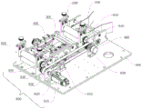
The utility model discloses a laser cutting forming device, which comprises a bottom plate, a laser cutting mechanism arranged on the bottom plate, and a feeding mechanism, a width adjusting mechanism and a discharging mechanism which are arranged on the bottom plate in sequence; the laser cutting mechanism is arranged above the width adjusting mechanism and is used for cutting a workpiece; the width adjusting mechanism comprises a first power assembly and two groups of first limiting assemblies, and the first power assembly is connected with each group of the first limiting assemblies; the first limiting assemblies are arranged on the bottom plate and are arranged on two sides of the transmission direction of the workpiece, and the first power assembly drives the two groups of first limiting assemblies to move oppositely or oppositely so as to limit the width direction of the workpiece.
Description
Technical Field
The utility model relates to a laser cutting field, concretely designs a laser cutting former.
Background
In recent years, China has made a great development in the field of automated production, and with the continuous change of the demands of customers, the pace of product updating is also continuously accelerated, and the requirements on automated equipment are also stricter and stricter, mainly reflected on the requirements on the universality of the equipment.
When laser cutting forming equipment designed by a plurality of manufacturers at the present stage is used for cutting a machined part, the machined part is easy to deviate due to the fact that the machined part is not limited in the width direction, and accordingly the cutting is inaccurate.
SUMMERY OF THE UTILITY MODEL
The utility model aims at providing a laser cutting former can carry on spacingly to the width direction of machined part for thereby the machined part is difficult to take place to squint the degree of accuracy that improves the cutting at the in-process of conveying.
The utility model discloses a laser cutting forming device, which comprises a bottom plate, a laser cutting mechanism arranged on the bottom plate, and a feeding mechanism, a width adjusting mechanism and a discharging mechanism which are arranged on the bottom plate in sequence; the laser cutting mechanism is arranged above the width adjusting mechanism and is used for cutting a workpiece; the width adjusting mechanism comprises a first power assembly and two groups of first limiting assemblies; the first limiting assemblies are arranged on the bottom plate and are positioned on two sides of the transmission direction of the workpiece; the first power assemblies are respectively connected with the two groups of first limiting assemblies; the first power assembly drives the two groups of first limiting assemblies to move relatively or oppositely so as to limit the width direction of the workpiece.
Optionally, the laser cutting forming equipment further comprises a feeding shaping mechanism, and the feeding shaping mechanism is arranged on one side of the feeding mechanism, which is far away from the width adjusting mechanism; the feeding shaping mechanism comprises a second power assembly and two groups of second limiting assemblies; the second limiting assemblies are arranged on the bottom plate and are positioned on two sides of the conveying direction of the workpiece; the second power assembly is connected with each group of second limiting assemblies; the second power assembly drives the two groups of second limiting assemblies to move oppositely or oppositely so as to limit the width direction of the workpiece.
Optionally, the laser cutting and forming equipment further comprises a front tensioning mechanism and a rear tensioning mechanism which are arranged on the bottom plate; the front tensioning mechanism is arranged between the feeding mechanism and the width adjusting mechanism, and the rear tensioning mechanism is arranged between the width adjusting mechanism and the discharging mechanism; the front tensioning mechanism and the rear tensioning mechanism are used for keeping the workpiece in a tensioning state.
Optionally, the first power assembly and the second power assembly both comprise a screw rod adjusting head and a screw rod; the screw rod is connected with a screw rod adjusting head, and the screw rod adjusting head is used for driving the screw rod to rotate; threads with opposite lines are respectively arranged at the two ends of the screw rod; the two groups of first limiting assemblies are respectively arranged at two ends of a screw rod of the first power assembly; and the two groups of second limiting assemblies are respectively arranged at two ends of a screw rod of the second power assembly.
Optionally, each group of first limiting assemblies includes a limiting plate, a roller fixing plate, and a roller; the limiting plate is arranged on the bottom plate, the roller fixing plate is arranged above the limiting plate, and the rollers are arranged on the inner side of the roller fixing plate; the roller is used for pressing the edge of the workpiece.
Optionally, each group of the first limiting assemblies further comprises an upper blowing block and a lower blowing block; the upper air blowing block and the lower air blowing block are respectively arranged on the upper side and the lower side of the limiting plate; the upper air blowing block and the lower air blowing block are both connected with air pipe joints.
Optionally, the feeding mechanism and the discharging mechanism both comprise a supporting seat, an upper roller shaft and a lower roller shaft; the supporting seat is arranged on the bottom plate, two ends of the lower roll shaft are respectively connected to two sides of the supporting seat, and the upper roll shaft is arranged above the lower roll shaft; the movable plate is arranged on each of two sides of the supporting seat, the top of each movable plate is connected with one end of a spring pressing block, the other end of each spring pressing block is connected with a locking screw, threaded holes are formed in the tops of two sides of the supporting seat, the locking screws penetrate through the threaded holes, and two ends of the upper roll shaft are connected to the two movable plates respectively.
Optionally, the front tensioning mechanism and the rear tensioning mechanism both comprise a support frame, a tensioning shaft, two adjusting blocks and two springs; the support frame sets up on the bottom plate, every the adjusting block activity respectively sets up the support frame both sides, the slotted hole has been seted up respectively to the support frame both sides, the tensioning axle both ends set up respectively in two slotted holes, every tensioning axle and adjusting block are connected respectively to the spring both ends.
Optionally, the feeding shaping mechanism further comprises a mounting seat, a shaping rod and a height horizontal shaft; the mounting seat is arranged on the bottom plate, and the two ends of the shaping rod and the two ends of the height horizontal shaft are respectively connected to the two sides of the mounting seat; the installation height of the shaping rod is lower than that of the height horizontal shaft, and the height of the height horizontal shaft is lower than that of the upper stick shaft.
Optionally, the laser cutting and forming device further comprises a driving mechanism, wherein the driving mechanism comprises a motor, a synchronous belt, two synchronous wheels, two first gears, two second gears and an encoder; each first gear and each second gear are respectively connected with an upper roll shaft and a lower roll shaft, each first gear and each second gear are mutually meshed, each first gear is respectively connected with each synchronous wheel, the motor is connected with one of the synchronous wheels, the other synchronous wheel is connected with an encoder, and the synchronous belts are arranged on the two synchronous wheels.
Has the advantages that: the feeding mechanism conveys the machined part to the width adjusting mechanism, the first power assemblies are adjusted according to the width of the machined part, then the two sets of first limiting assemblies are adjusted to move oppositely or oppositely to limit the width direction of the machined part, the machined part is prevented from being cut inaccurately due to deviation in the conveying process, and the machined part flows out of the discharging mechanism after the laser cutting mechanism cuts the machined part. Through setting up first power component, the removal of first spacing subassembly just can be adjusted to first power component like this for first spacing subassembly can be relative or move in opposite directions so that carry on spacingly on the width direction of machined part, and the machined part just can not take place the skew, and the degree of accuracy of cutting will improve greatly.
Drawings
The accompanying drawings, which are included to provide a further understanding of the embodiments of the invention and are incorporated in and constitute a part of this specification, illustrate embodiments of the invention and together with the description serve to explain the principles of the invention. It is obvious that the drawings in the following description are only some embodiments of the invention, and that for a person skilled in the art, other drawings can be derived from them without inventive faculty. In the drawings:
fig. 1 is a schematic structural view of the laser cutting and forming device of the present invention;
FIG. 2 is another schematic structural view of the laser cutting and forming apparatus of FIG. 1;
FIG. 3 is a schematic structural view of the feed shaping mechanism of FIG. 1;
FIG. 4 is a schematic structural view of the feeding mechanism of FIG. 1;
FIG. 5 is a schematic structural view of the front tensioning mechanism of FIG. 1;
FIG. 6 is a schematic structural view of the width adjustment mechanism of FIG. 1;
fig. 7 is a schematic structural view of the laser cutting mechanism of fig. 1.
Wherein:
the feeding shaping mechanism 100, the mounting seat 110, the shaping rod 130, the height horizontal shaft 140, the second power assembly 150, the screw rod adjusting head 151, the screw rod 152, the second limiting assembly 160, the first linear slide rail 170, the feeding mechanism 200, the supporting seat 210, the locking screw 220, the upper roller 230, the lower roller 240, the moving plate 250, the spring pressing block 260, the front tensioning mechanism 300, the tensioning shaft 310, the supporting frame 320, the adjusting block 330, the spring 340, the tensioning horizontal shaft 350, the horizontal shaft bearing 360, the width adjusting mechanism 400, the first power assembly 410, the first limiting assembly 420, the limiting plate 421, the roller fixing plate 422, the roller 423, the upper blowing block 424, the lower blowing block 425, the air pipe joint 426, the second linear slide rail 440, the rear tensioning mechanism 500, the discharging mechanism 600, the laser cutting mechanism 700, the laser head 710, the manual adjusting platform 720, the platform moving plate 730, the laser mounting plate 740, and the reinforcing ribs 750, the device comprises a driving mechanism 800, a motor 810, a synchronous belt 820, a synchronous wheel 830, a first gear 840, a second gear 850, an encoder 860, a tensioning assembly 870, a bottom plate 900 and a workpiece 1.
Detailed Description
In the description of the present invention, the terms "first" and "second" are used for descriptive purposes only and are not to be construed as indicating relative importance or as implying any number of indicated technical features. Thus, unless otherwise specified, a feature defined as "first" or "second" may explicitly or implicitly include one or more of that feature; "plurality" means two or more. The terms "comprises" and "comprising," and any variations thereof, are intended to cover a non-exclusive inclusion, such that one or more other features, integers, steps, operations, elements, mechanisms, and/or combinations thereof may be present or added.
The invention will now be described in detail with reference to the accompanying figures 1 to 7 and alternative embodiments.
As shown in fig. 1 and fig. 2, the utility model discloses a laser cutting forming device, which comprises a bottom plate 900, a laser cutting mechanism 700 arranged on the bottom plate 900, and a feeding mechanism 200, a width adjusting mechanism 400 and a discharging mechanism 600 which are arranged on the bottom plate 900 in sequence; the laser cutting mechanism 700 is arranged above the width adjusting mechanism 400 and used for cutting a workpiece; the width adjustment mechanism 400 includes a first power assembly 410 and two sets of first limit assemblies 420; the first limiting assemblies 420 are arranged on the bottom plate 900 and are positioned at two sides of the transmission direction of the workpiece 1; the first power assembly 410 is respectively connected with the two groups of first limiting groups 420; the first power assembly 410 drives the two sets of first limiting assemblies 420 to move relatively or oppositely, so as to limit the width direction of the workpiece 1.
The feeding mechanism 200 conveys the workpiece 1 to the width adjusting mechanism 400, the first power assembly 410 is adjusted according to the width of the workpiece 1, and then the two groups of first limiting assemblies 420 are adjusted to move relatively or oppositely to limit the width direction of the workpiece 1, so that the workpiece 1 is prevented from being cut inaccurately due to deviation in the conveying process, and after the workpiece 1 is cut by the laser cutting mechanism 700, the workpiece 1 flows out of the discharging mechanism 600. Through setting up first power component 410, first power component 410 just can adjust the removal of first spacing subassembly 420 like this for first spacing subassembly 420 can move relatively or in opposite directions so that carry out spacingly on the width direction of machined part 1, and machined part 1 just can not take place the skew, and the degree of accuracy of cutting will improve greatly.
In this embodiment, the workpiece 1 is a copper belt, but may be other metal belts or plastic belts.
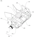
Further, as shown in fig. 3, the laser cutting forming apparatus further includes a feeding shaping mechanism 100, the feeding shaping mechanism 100 is disposed on one side of the feeding mechanism 200 away from the width adjusting mechanism 400, the feeding shaping mechanism 100 includes a second power assembly 150 and two sets of second limiting assemblies 160, the second limiting assemblies 160 are disposed on the bottom plate 900 and located on two sides of the conveying direction of the workpiece 1, the second power assembly 150 is connected with each set of second limiting assemblies 160, the second power assembly 150 is used for driving the two sets of second limiting assemblies 160 to move relatively or oppositely, and the two sets of second limiting assemblies 160 are used for limiting the width direction of the workpiece 1.
Specifically, the first power assembly 410 and the second power assembly 150 both include a screw rod adjusting head 151 and a screw rod 152, the screw rod 152 is connected with the screw rod adjusting head 151, the screw rod adjusting head 151 is used for driving the screw rod 152 to rotate, threads with opposite textures are respectively arranged at two ends of the screw rod 152, two sets of first limiting assemblies 420 are respectively arranged at two ends of the screw rod 152 of the first power assembly 410, two sets of second limiting assemblies 160 are respectively arranged at two ends of the screw rod 152 of the second power assembly 150, and thus the screw rod 152 can drive the two sets of second limiting assemblies 160 or the first limiting assemblies 420 to move relatively or oppositely.
Further, the feeding shaping mechanism 100 further comprises a mounting seat, two shaping rods 130 and a height horizontal shaft 140, the mounting seat is arranged on the bottom plate 900, and two ends of each shaping rod 130 and two ends of each height horizontal shaft 140 are respectively connected to two sides of the mounting seat. It should be noted that the screw rod adjusting head 151 is disposed on one side of the mounting seat, two ends of the screw rod 152 are respectively connected to two ends of the mounting seat, the second limiting assembly 160 includes a limiting metal plate, the limiting metal plate is disposed on two sides of the conveying direction of the workpiece 1, the limiting metal plate limits two sides of the workpiece 1, specifically, the feeding shaping mechanism 100 further includes two first linear sliding rails 170, and the second limiting assembly 160 is disposed on the first linear sliding rails 170, so that friction force generated by movement of the second limiting assembly 160 can be reduced. The side edge of the workpiece 1 is limited by the second limiting component 160, and the height position of the workpiece 1 is adjusted by the shaping rod 130 and the height horizontal shaft 140, so that the workpiece 1 is pre-limited in the width direction and the height position by the feeding shaping mechanism 100 before entering the feeding mechanism 200, specifically, the installation height of the shaping rod 130 is lower than that of the height horizontal shaft 140, and the installation height of the height horizontal shaft 140 is lower than that of the upper roller 230, so that the workpiece can be gradually lifted and conveyed.
Further, as shown in fig. 4, fig. 4 is a schematic structural diagram of a feeding mechanism, and the feeding mechanism 200 and the discharging mechanism 600 both include a supporting seat 210, an upper roller 230, and a lower roller 240; the supporting seat 210 is arranged on the bottom plate 900, two ends of the lower roller shaft 230 are respectively connected to two sides of the supporting seat 210, and the upper roller shaft 230 is arranged above the lower roller shaft 240; the two sides of the supporting seat 210 are respectively provided with a moving plate 250, the top of the moving plate 250 is connected with one end of a spring pressing block 260, the other end of the spring pressing block 260 is connected with a locking screw 220, the top of the two sides of the supporting seat 210 is provided with a threaded hole, the locking screw 220 is arranged in the threaded hole in a penetrating manner, and the two ends of the upper roller shaft 230 are respectively connected to the two moving plates 250. The locking screw 221 is rotated to enable the locking screw 221 to move downwards so as to drive the spring pressing block 222 to move downwards to press the upper roller shaft 230, therefore, the distance between the upper roller shaft 230 and the lower roller shaft 240 can be finely adjusted, the workpiece 1 is conveyed forwards by means of the friction force of the upper roller shaft 230 and the lower roller shaft 240 to the surface of the workpiece 1, the conveying friction force can be adjusted by adjusting the distance between the upper roller shaft 230 and the lower roller shaft 240, and the workpiece 1 can be guaranteed to be conveyed forwards all the time by adjusting the distance between the upper roller shaft 230 and the lower roller shaft 240 to a proper distance.
It should be noted that the surface of the upper roller 230 and the lower roller 240 is coated with rubber to increase the friction between the roller and the workpiece 1, so as to ensure that the workpiece 1 does not slip during transportation.
It should be noted that the structure of the feeding mechanism 200 is the same as that of the discharging mechanism 600.
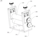
Further, as shown in fig. 5, the laser cutting forming apparatus further includes a front tensioning mechanism 300 and a rear tensioning mechanism 500 which are arranged on the bottom plate 900, the front tensioning mechanism 300 is arranged between the feeding mechanism 200 and the width adjusting mechanism 400, the rear tensioning mechanism 500 is arranged between the width adjusting mechanism 400 and the discharging mechanism 600, the front tensioning mechanism 300 and the rear tensioning mechanism 500 each include a tensioning shaft 310, a supporting frame 320, two adjusting blocks 330, two springs 340, a tensioning horizontal shaft 350 and a horizontal shaft bearing 360, the supporting frame 320 is arranged on the bottom plate 900, two ends of the tensioning horizontal shaft 350 are respectively arranged on two sides of the supporting frame 320 through the horizontal shaft bearing 360, and the workpiece 1 can be kept flat during movement by arranging the tensioning horizontal shaft 350. Wherein, slotted holes are arranged on both sides of the supporting frame 320, both ends of the tensioning shaft 310 are arranged in the slotted holes, and the tensioning shaft 310 can move up and down along the direction of the slotted holes; each adjusting block 330 is movably arranged at two sides of the supporting frame 320, one end of the spring 340 is connected with the adjusting block 330, and the other end is connected with the tensioning shaft 310; the tensioning degree of the workpiece 1 can be adjusted by adjusting the position of the adjusting block 330, and thus the tension of the spring 340, and specifically, the height of the tensioning shaft 310 is lower than the height of the tensioning horizontal shaft 350 and lower than the height of the workpiece 1 entering the width adjusting mechanism 400, so that if the tensioning degree of the workpiece 1 needs to be increased, the adjusting block 330 is moved downward, so that the spring 340 is stretched, and the spring gives a downward tension to the tensioning shaft 310. After the workpiece 1 enters the front tensioning mechanism 300, the width adjusting mechanism 400 and the rear tensioning mechanism 500 from the feeding mechanism 200, the tensioning shafts 310 of the front tensioning mechanism 300 and the rear tensioning mechanism 500 are used for pressing the surface of the workpiece 1, so that the workpiece is in a horizontal tensioning state, the copper strip can be prevented from shifting and shaking in the conveying process, and the accurate cutting of the workpiece 1 by the laser cutting mechanism 700 can be ensured.
It should be noted that the front tensioning mechanism 300 and the rear tensioning mechanism 500 have the same structure.
Further, as shown in fig. 6, the width adjusting mechanism 400 includes a first power assembly 410 and two sets of first limiting assemblies 420, the first limiting assemblies 240 are disposed on the bottom plate 900 and located at two sides of the transmission direction of the workpiece 1, the first power assembly 410 is connected to each set of first limiting assemblies 420, the first power assembly 410 is used for driving the two sets of first limiting assemblies 420 to move relatively or relatively, and the two sets of first limiting assemblies 420 are used for limiting the width direction of the workpiece 1; first power component 410 includes lead screw adjustment head 151, lead screw 152 is connected with lead screw adjustment head 151, lead screw adjustment head 151 is used for driving lead screw 152 to rotate, lead screw 152 both ends are provided with the opposite screw thread of line respectively, two sets of first spacing subassemblies 420 set up respectively at lead screw 152 both ends, through set up the opposite screw thread of line on lead screw 152, when lead screw 152 rotates, just can make two sets of first spacing subassemblies 420 relative or the phase shift, just can carry on spacingly on the width direction of machined part 1, just can adjust the removal of two sets of first spacing subassemblies 420 when the width of machined part 1 changes like this, in order to adapt to carry on spacingly to the machined part 1 of different width.
Each set of first limiting component 420 comprises a limiting plate 421, a roller fixing plate 422 and a roller 423, wherein the roller 423 is arranged on the inner side of the roller fixing plate 422, the roller fixing plate 422 is arranged above the limiting plate 421, the limiting plate 421 is arranged on the bottom plate 900, the roller 423 is used for compressing the edge of the workpiece 1, and the workpiece 1 can be prevented from shaking in the moving process by arranging the edge of the roller 423 compressed the workpiece 1. Each set of first limiting assembly 420 further comprises an upper air blowing block 424 and a lower air blowing block 425, the upper air blowing block 424 and the lower air blowing block 425 are respectively arranged on the upper side and the lower side of the limiting plate 421, the upper air blowing block 424 and the lower air blowing block 425 are both used for blowing shielding air, a protector can be blown out of the surface of the workpiece 1 through the arrangement of the upper air blowing block 424 and the lower air blowing block 425, and particularly, the upper air blowing block 424 and the lower air blowing block 425 are both connected with an air pipe joint 426. The width adjustment mechanism 400 further includes a second linear sliding rail 440, the first limiting component 420 is disposed on the second linear sliding rail 440, and the friction force generated by the movement of the first limiting component 420 can be reduced by disposing the second linear sliding rail 440.
Further, as shown in fig. 7, the laser cutting mechanism 700 includes a laser head 710, a manual adjustment platform 720, a platform moving plate 730, a laser mounting plate 740, and a reinforcing rib 750, wherein the laser head 710 is a galvanometer laser head, the platform moving plate 730 is mounted on the manual adjustment platform 720, the laser mounting plate 740 is mounted on the platform moving plate 730, the bottom of the reinforcing rib 750 is connected to the platform moving plate 730, and the side of the reinforcing rib is connected to the laser mounting plate 740. Manual adjustment platform 720 accessible manual pivoted mode adjusts the high position of galvanometer laser head 710, guarantees that laser focus can effectively cut the copper strips.
Further, as shown in fig. 2, the laser cutting and forming apparatus further includes a driving mechanism, the driving mechanism includes a motor 810, a synchronous belt 820, two synchronous wheels 830, two first gears 840 and two second gears 850, an encoder 860, and a tensioning assembly 870, each first gear 840 and each second gear 850 are respectively connected to the upper roller shaft 230 and the lower roller shaft 240, each first gear 840 and each second gear 850 are meshed with each other, each first gear 840 is respectively connected to the synchronous wheel 830, the motor 810 is connected to one of the synchronous wheels 830, the other synchronous wheel 830 is connected to the encoder 860, the synchronous belt 820 is disposed on the two synchronous wheels 830, the synchronous belt 820 of the synchronous wheels 830 is used as a transmission mode to drive the feeding mechanism 200 and the discharging mechanism 600 to rotate simultaneously, and it is ensured that how many copper tapes are fed out and how many copper tapes are fed in. The encoder 860 is connected with the lower roller shaft 240 of the feeding mechanism 200, transmits the movement speed of the copper strip to the controller in real time, and forms closed-loop control with the laser cutting speed of the galvanometer so as to ensure the cutting precision of the copper strip; the tensioning assembly 870 is disposed on the mounting base plate 900 and is mainly used to tension the synchronous belt 820, so as to ensure that the synchronous belt 820 is always in a proper tightness state.
The working process is as follows: workpiece 1 uses the copper strips as an example, at first the copper strips enter into feed mechanism 200 after through the pre-limit of pan feeding plastic mechanism 100 and height adjustment, under the effect of last roller 230 and lower roller 240, the copper strips is conveyed into preceding straining device 300, enter into width adjustment mechanism 400 after the tensioning of tensioning axle 310 to the copper strips, carry out spacingly through first spacing subassembly 420 to the width direction of copper strips again, laser cutting mechanism 700 cuts the copper strips through laser head 710, later the copper strips is through tensioning mechanism 500 after again, wherein preceding straining device 300 makes the copper strips be in the state of tensioning with tensioning mechanism 500 combined action after, later the copper strips rethread discharge mechanism 600 flows.
The foregoing is a more detailed description of the invention in connection with specific alternative embodiments, and it is not intended that the invention be limited to these specific details. To the utility model belongs to the technical field of ordinary technical personnel, do not deviate from the utility model discloses under the prerequisite of design, can also make a plurality of simple deductions or replacement, all should regard as belonging to the utility model discloses a protection scope.
Claims (10)
1. A laser cutting forming device is characterized by comprising a bottom plate, a laser cutting mechanism arranged on the bottom plate, and a feeding mechanism, a width adjusting mechanism and a discharging mechanism which are sequentially arranged on the bottom plate; the laser cutting mechanism is arranged above the width adjusting mechanism and is used for cutting a workpiece; the width adjusting mechanism comprises a first power assembly and two groups of first limiting assemblies; the first limiting assemblies are arranged on the bottom plate and are positioned on two sides of the transmission direction of the workpiece; the first power assemblies are respectively connected with the two groups of first limiting assemblies; the first power assembly drives the two groups of first limiting assemblies to move relatively or oppositely so as to limit the width direction of the workpiece.
2. The laser cutting and forming device as claimed in claim 1, further comprising a feeding shaping mechanism, wherein the feeding shaping mechanism is arranged on a side of the feeding mechanism far away from the width adjusting mechanism; the feeding shaping mechanism comprises a second power assembly and two groups of second limiting assemblies; the second limiting assemblies are arranged on the bottom plate and are positioned on two sides of the conveying direction of the workpiece; the second power assembly is connected with each group of second limiting assemblies; the second power assembly drives the two groups of second limiting assemblies to move oppositely or oppositely so as to limit the width direction of the workpiece.
3. The laser cutting and forming device according to claim 1, further comprising a front tensioning mechanism and a rear tensioning mechanism provided on the base plate; the front tensioning mechanism is arranged between the feeding mechanism and the width adjusting mechanism, and the rear tensioning mechanism is arranged between the width adjusting mechanism and the discharging mechanism; the front tensioning mechanism and the rear tensioning mechanism are used for keeping the workpiece in a tensioning state.
4. The laser cutting and forming device according to claim 2, wherein the first power assembly and the second power assembly each comprise a lead screw adjusting head, a lead screw; the screw rod is connected with a screw rod adjusting head, and the screw rod adjusting head is used for driving the screw rod to rotate; threads with opposite lines are respectively arranged at the two ends of the screw rod; the two groups of first limiting assemblies are respectively arranged at two ends of a screw rod of the first power assembly; and the two groups of second limiting assemblies are respectively arranged at two ends of a screw rod of the second power assembly.
5. The laser cutting and forming equipment according to claim 1, wherein each group of the first limiting assemblies comprises a limiting plate, a roller fixing plate and a roller; the limiting plate is arranged on the bottom plate, the roller fixing plate is arranged above the limiting plate, and the rollers are arranged on the inner side of the roller fixing plate; the roller is used for pressing the edge of the workpiece.
6. The laser cutting and forming device according to claim 5, wherein each set of the first limiting assemblies further comprises an upper blowing block and a lower blowing block; the upper air blowing block and the lower air blowing block are respectively arranged on the upper side and the lower side of the limiting plate; the upper air blowing block and the lower air blowing block are both connected with air pipe joints.
7. The laser cutting and forming device as claimed in claim 2, wherein the feeding mechanism and the discharging mechanism each comprise a supporting seat, an upper roller shaft and a lower roller shaft; the supporting seat is arranged on the bottom plate, two ends of the lower roll shaft are respectively connected to two sides of the supporting seat, and the upper roll shaft is arranged above the lower roll shaft; the movable plate is arranged on each of two sides of the supporting seat, the top of each movable plate is connected with one end of a spring pressing block, the other end of each spring pressing block is connected with a locking screw, threaded holes are formed in the tops of two sides of the supporting seat, the locking screws penetrate through the threaded holes, and two ends of the upper roll shaft are connected to the two movable plates respectively.
8. The laser cutting and forming device according to claim 3, wherein the front tensioning mechanism and the rear tensioning mechanism each comprise a support frame, a tensioning shaft, two adjusting blocks, two springs; the support frame sets up on the bottom plate, every the adjusting block activity respectively sets up the support frame both sides, the slotted hole has been seted up respectively to the support frame both sides, the tensioning axle both ends set up respectively in two slotted holes, every tensioning axle and adjusting block are connected respectively to the spring both ends.
9. The laser cutting and forming device as claimed in claim 7, wherein the feeding and shaping mechanism further comprises a mounting seat, a shaping rod and a height horizontal shaft; the mounting seat is arranged on the bottom plate, and the two ends of the shaping rod and the two ends of the height horizontal shaft are respectively connected to the two sides of the mounting seat; the installation height of the shaping rod is lower than that of the height horizontal shaft, and the installation height of the height horizontal shaft is lower than that of the upper roll shaft.
10. The laser cutting and forming device according to claim 7, further comprising a driving mechanism, wherein the driving mechanism comprises a motor, a synchronous belt, two synchronous wheels, two first gears and two second gears, and an encoder; each first gear and each second gear are respectively connected with an upper roll shaft and a lower roll shaft, each first gear and each second gear are mutually meshed, each first gear is respectively connected with each synchronous wheel, the motor is connected with one of the synchronous wheels, the other synchronous wheel is connected with an encoder, and the synchronous belts are arranged on the two synchronous wheels.
Priority Applications (1)
| Application Number | Priority Date | Filing Date | Title |
|---|---|---|---|
| CN202022618913.3U CN214518231U (en) | 2020-11-12 | 2020-11-12 | Laser cutting former |
Applications Claiming Priority (1)
| Application Number | Priority Date | Filing Date | Title |
|---|---|---|---|
| CN202022618913.3U CN214518231U (en) | 2020-11-12 | 2020-11-12 | Laser cutting former |
Publications (1)
| Publication Number | Publication Date |
|---|---|
| CN214518231U true CN214518231U (en) | 2021-10-29 |
Family
ID=78288100
Family Applications (1)
| Application Number | Title | Priority Date | Filing Date |
|---|---|---|---|
| CN202022618913.3U Active CN214518231U (en) | 2020-11-12 | 2020-11-12 | Laser cutting former |
Country Status (1)
| Country | Link |
|---|---|
| CN (1) | CN214518231U (en) |
Cited By (1)
| Publication number | Priority date | Publication date | Assignee | Title |
|---|---|---|---|---|
| CN114523218A (en) * | 2022-04-02 | 2022-05-24 | 广州长仁工业科技有限公司 | Laser cutting device for steel plate |
-
2020
- 2020-11-12 CN CN202022618913.3U patent/CN214518231U/en active Active
Cited By (1)
| Publication number | Priority date | Publication date | Assignee | Title |
|---|---|---|---|---|
| CN114523218A (en) * | 2022-04-02 | 2022-05-24 | 广州长仁工业科技有限公司 | Laser cutting device for steel plate |
Similar Documents
| Publication | Publication Date | Title |
|---|---|---|
| CN110449482B (en) | Cold roll forming assembly line for thin steel plate | |
| CN214518231U (en) | Laser cutting former | |
| CN210732845U (en) | Plate cutting device and large plate cutting machine comprising same | |
| CN212714245U (en) | Cloth slitting equipment | |
| CN210585961U (en) | Stamping part sorting unit | |
| CN210878129U (en) | Automatic material cutting equipment | |
| CN214527242U (en) | Automatic slitting equipment | |
| CN110605487A (en) | Automatic material cutting equipment | |
| CN115257020B (en) | Automatic production line for extrusion, molding, conveying and cutting of GPPS (general purpose polystyrene) plates | |
| CN216656516U (en) | Angle-adjustable cutting device for machining clutch steel sheet | |
| CN107253225B (en) | The method comprises the following steps of: sponge cutting machine | |
| CN206535920U (en) | Rolling screen door door piece clicker press machine | |
| CN213259832U (en) | Pull belt blanking device | |
| CN213945316U (en) | Laser plate cutting machine with jacking loading attachment | |
| CN105171791B (en) | A kind of silica gel automatic machining device | |
| CN112024978B (en) | Interval adjusting device of panel cutting usefulness | |
| CN109366601B (en) | Four-station conductive adhesive tape slitter | |
| CN216423455U (en) | High-precision full-automatic film sticking machine | |
| CN220787557U (en) | Automatic geotechnical cloth feeding equipment | |
| CN113879896B (en) | Cutting equipment | |
| CN220098072U (en) | Automatic adhesive tape cutting machine | |
| CN214602161U (en) | Steel plate feeding and shearing device for manufacturing filter element framework | |
| CN216758876U (en) | Speed measurer assembling and screw locking machine for motor assembly | |
| CN216884133U (en) | Paper shifting assisting precision cutting machine | |
| CN215614603U (en) | Lifting type servo feeder |
Legal Events
| Date | Code | Title | Description |
|---|---|---|---|
| GR01 | Patent grant | ||
| GR01 | Patent grant | ||
| TR01 | Transfer of patent right |
Effective date of registration: 20220919 Address after: 518000 workshop 501, building 3, intelligent manufacturing center park, No. 12, Chongqing Road, Heping community, Fuhai street, Bao'an District, Shenzhen City, Guangdong Province Patentee after: Shenzhen Han's lithium battery intelligent equipment Co.,Ltd. Address before: 518000 No. 9988 Shennan Road, Nanshan District, Shenzhen, Guangdong Patentee before: HAN'S LASER TECHNOLOGY INDUSTRY GROUP Co.,Ltd. |
|
| TR01 | Transfer of patent right |