CN214498525U - Detachable and portable reinforcing steel bar protection shed - Google Patents
Detachable and portable reinforcing steel bar protection shed Download PDFInfo
- Publication number
- CN214498525U CN214498525U CN202120383399.1U CN202120383399U CN214498525U CN 214498525 U CN214498525 U CN 214498525U CN 202120383399 U CN202120383399 U CN 202120383399U CN 214498525 U CN214498525 U CN 214498525U
- Authority
- CN
- China
- Prior art keywords
- detachable
- portable
- protection shed
- supporting
- purlin
- Prior art date
- Legal status (The legal status is an assumption and is not a legal conclusion. Google has not performed a legal analysis and makes no representation as to the accuracy of the status listed.)
- Active
Links
Images


Abstract
The utility model relates to the technical field of building engineering facilities, in order to solve the technical problems of inconvenient disassembly and transportation, time and labor waste, large workload and high cost of the prior reinforcing steel bar protection shed, the utility model provides a detachable and portable reinforcing steel bar protection shed, which comprises a plurality of supporting structures, two adjacent supporting structures are connected through purlins, a cover body is arranged on the purlins, each supporting structure comprises a supporting column, an inclined strut and a frame body, the frame bodies are arranged on the supporting columns through bolts, the inclined struts are respectively connected with the supporting columns and the frame bodies through bolts, the end parts of the purlins are provided with mounting holes, the purlins are connected between the adjacent frame bodies through bolts, the bolt connection mode is convenient for disassembly, the frame bodies facing to the outer side are also provided with cornice frames for extending the top space, and the detachable reinforcing steel bar protection shed has detachability, convenient transportation, strong practicability and working hours saving, and achieves the purpose of reducing the engineering cost.
Description
Technical Field
The utility model relates to a building engineering facility technical field, concretely relates to can dismantle portable reinforcing bar protection canopy.
Background
A large amount of steel bars need to be processed on site in the building construction process, and in order to facilitate the transportation and management of materials, a steel bar protection shed needs to be arranged on a steel bar processing site. Traditional large-scale reinforcing bar protection canopy area is big, and to the narrow and small construction place of area, reinforcing bar processing field area is narrow, if utilize traditional large-scale reinforcing bar protection canopy, just occupies great place, leads to reinforcing bar processing difficulty, and traditional large-scale reinforcing bar protection canopy is whole welding, and it is also inconvenient to dismantle and transport, wastes time and energy, and work load is great, leads to overall cost high.
Therefore, in view of the above, there is a need for a detachable and portable reinforcement protection shed that solves the problems.
SUMMERY OF THE UTILITY MODEL
In order to solve current reinforcing bar protection canopy and dismantle and transport inconvenience, waste time and energy, work load is great, lead to technical problem with high costs, the utility model provides a can dismantle portable reinforcing bar protection canopy, including a plurality of bearing structures, two adjacent bearing structures pass through the purlin and connect, install the lid on the purlin, bearing structure includes the support column, bracing and framework, the framework passes through the bolt and installs on the support column, the bracing passes through the bolt respectively with the support column, the framework is connected, the purlin tip is provided with the mounting hole, the purlin passes through bolted connection between adjacent framework, bolted connection mode convenient to detach, eaves frame that is used for extending the headspace still is installed to the framework towards the outside, have detachability, convenient transportation, the practicality is strong and save man-hour advantage, the mesh that has reached reduction engineering cost.
In order to achieve the above purpose, the technical scheme of the utility model is realized like this:
the utility model provides a can dismantle portable reinforcing bar protection canopy, includes a plurality of bearing structures, bearing structure passes through the purlin to be connected, installs the lid on the purlin, and bearing structure includes support column, bracing and framework, and the framework passes through the bolt and installs on the support column, and the bracing passes through the bolt to be connected with support column, framework respectively, and the purlin tip is provided with the mounting hole, and the purlin passes through bolted connection between adjacent framework, still installs towards the framework of outside and is used for extending the eaves frame in headspace.
Furthermore, a bottom plate is arranged at the bottom of the supporting column, and a reinforcing rib is further arranged between the supporting column and the bottom plate.
Further, the top of the supporting column is provided with a top plate, and the top plate is used for connecting the frame body.
Further, the framework comprises a main cross beam, a main connecting portion connected with the top plate is arranged at the bottom of the main cross beam, a plurality of longitudinal beams are connected to the upper portion of the main cross beam, a secondary cross beam is connected to the upper portion of each longitudinal beam, a third installation portion is arranged at the joint of the main cross beam and the corresponding longitudinal beam, first installation portions and second installation portions are respectively arranged on the two sides of the joint of the longitudinal beams and the secondary cross beam and are used for being connected with purlins and/or eaves frames, and the main cross beam, the longitudinal beams and the secondary cross beam are enclosed into a latticed structure.
Preferably, the upper portion is provided with the fixing base in the support column, and main connecting portion both sides are provided with vice connecting portion, and the bracing both ends are provided with the otic placode respectively, and the bracing passes through the otic placode to be connected with fixing base, vice connecting portion respectively.
Preferably, diagonal rods are attached to opposite corners of the lattice structure.
Preferably, the purlines on the middle of the upper layer and the purlines on the edge of the lower layer are connected with oblique cover bodies.
Preferably, the first installation part, the second installation part and the third installation part are angle steels, and the support column is I-shaped steel.
Preferably, the corner joints of the bottom plate are round corners.
Preferably, the length of purlin is 6000mm, and the length of main beam is 5000mm, and the length of support column is 3000mm, and the length of longeron is 600 mm.
Implement the utility model discloses the beneficial effect who brings is:
the utility model provides a can dismantle portable reinforcing bar protection canopy, including a plurality of bearing structures, two adjacent bearing structures pass through the purlin and connect, install the lid on the purlin, can protect the reinforcing bar. The supporting structure comprises supporting columns, inclined struts and frame bodies, the frame bodies are installed on the supporting columns through bolts, the inclined struts are connected with the supporting columns and the frame bodies through bolts respectively, mounting holes are formed in the end portions of the purlines, the purlines are connected between adjacent frame bodies through bolts, the bolt connection mode is convenient to detach, and eaves frames used for extending the top space are further installed towards the frame bodies on the outer sides. In addition, a reinforcing rib is arranged between the supporting column and the bottom plate, so that the connection strength is enhanced, and the deformation is prevented; the frame body lattice structure can be connected with an upper layer purline and a lower layer purline, and the diagonal of the lattice structure is connected with diagonal rods, so that the structure is more stable; the inclined strut connects the support column and the frame body to make the support structure more stable; the middle purline on the upper layer and the edge purline on the lower layer are connected with an oblique cover body, so that the falling of the invaded rainwater is facilitated; the supporting column adopts I-shaped steel, the lateral rigidity is large, the bending resistance is strong, the two surfaces of the flange are parallel to each other, so that the connection, the processing and the installation are simple and convenient, compared with the common section steel, the cost is low, the precision is high, the residual stress is small, compared with a concrete structure, the I-shaped steel structure can increase the use area by 6 percent, the self weight of the structure is reduced, and the internal force of the structural design is reduced; the connecting part of the corners of the bottom plate is a fillet, so that the accidental injury to a human body is reduced, and the fillet can remove stress and remove residual burrs during processing; compare large-scale steel bar shed of tradition, the preferred size area of this embodiment is little, and it is all very convenient to dismantle or remove.
Drawings
Fig. 1 is an overall structure diagram of a steel bar protection shed provided by the embodiment of the utility model;
fig. 2 is a first supporting structure diagram provided in the embodiment of the present invention;
fig. 3 is an exploded view of a support structure provided in an embodiment of the present invention;
fig. 4 is a first installation state display diagram provided by the embodiment of the present invention;
fig. 5 is a second installation status display diagram provided by the embodiment of the present invention;
fig. 6 is a second supporting structure diagram provided in the embodiment of the present invention.
In the figure: a support pillar 10; a reinforcing rib 11; a base plate 12; a fixed base 13; a top plate 14; a diagonal brace 20; an ear plate 21; a frame body 30; a main cross member 31; the longitudinal beams 32; a secondary cross member 33; a main connecting portion 34; a secondary connecting portion 35; a first mounting portion 36; a second mounting portion 37; a third mounting portion 38; a diagonal rod 39; a cover 40; a purlin 41; a cornice 42.
Detailed Description
In order to make the technical solution of the present invention better understood, the technical solution of the embodiments of the present invention will be clearly and completely described below with reference to the accompanying drawings in the embodiments of the present invention, and it is obvious that the described embodiments are only some embodiments of the present invention, not all embodiments. Based on the embodiments of the present invention, all other embodiments obtained by a person of ordinary skill in the art without creative efforts shall fall within the protection scope of the present invention.
It should be noted that the terms "first," "second," and the like in the description and claims of the present invention and in the drawings described above are used for distinguishing between similar elements and not necessarily for describing a particular sequential or chronological order. It is to be understood that the data so used is interchangeable under appropriate circumstances such that the embodiments of the invention described herein are capable of operation in sequences other than those illustrated or otherwise described herein. Furthermore, the terms "comprises," "comprising," and any other variation thereof, are intended to cover a non-exclusive inclusion, such that a process, method, system, article, or apparatus that comprises a list of steps or elements is not necessarily limited to those steps or elements expressly listed, but may include other steps or elements not expressly listed or inherent to such process, method, article, or apparatus.
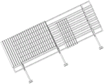
Referring to fig. 1, fig. 1 is the utility model provides a reinforcing bar protection canopy overall structure chart, a can dismantle portable reinforcing bar protection canopy, including a plurality of bearing structure, two adjacent bearing structure pass through the purlin 41 and connect, install lid 40 on the purlin 41, lid 40 is flat-plate or unsmooth alternate platelike structure. The ends of the purlins 41 are provided with mounting holes for connection by bolts.
Further, in order to prevent rainwater and/or sunshine invasion in advance, bearing structure still installs the eaves frame 42 that is used for extending the headspace, and eaves frame 42 can be with frame form or triangle form, preferred square frame form, and lid 40 covers eaves frame 42 top, is used for making the rainwater flow direction keep away from the distal end at the bottom of the main canopy on the one hand, and on the other hand is used for the sunshade, and then protects the reinforcing bar at the bottom of the canopy and avoids external adverse environmental factor to corrode.
Referring to fig. 2 and 3, fig. 2 and 3 are a supporting structure diagram and an exploded view thereof according to an embodiment of the present invention, the supporting structure includes a supporting column 10 and a frame 30, the frame 30 is installed on the supporting column 10, and is further provided with an inclined strut 20 for enhancing stability, the inclined strut 20 is respectively connected with the supporting column 10 and the frame 30, so as to form a stable triangular structure. The connecting plates are connected with each other in a bolt mode, so that the connecting plates are convenient to disassemble.
The bottom of the support column 10 is provided with a bottom plate 12, the bottom plate is provided with a mounting hole, and the mounting hole is used for being fixedly connected with an embedded bolt on the ground.
Further, in order to increase the strength of the joint surface between the supporting column 10 and the bottom plate 12 thereof, a reinforcing rib 11 is further arranged between the supporting column 10 and the bottom plate 12.
Further, in order to reduce the accidental injury of the bottom plate 12 to the human body, the corner connecting part of the bottom plate 12 is a round corner, and on the other hand, the round corner can remove stress and remove processing residual burrs.
The top plate 14 is arranged on the top of the supporting column 10, and the top plate 14 is provided with a mounting hole for connecting the frame body 30.
The upper-middle part of the support column 10 is provided with a fixed seat 13, and the fixed seat 13 is provided with a mounting hole for connecting with the inclined strut 20.
The supporting column 10 can be square steel, I-shaped steel, H-shaped steel, C-shaped steel or other types, preferably I-shaped steel, and the I-shaped steel has the advantages of wide flange, high lateral rigidity and high bending resistance; the two surfaces of the flange are parallel to each other, so that the connection, the processing and the installation are simple and convenient; compared with the common section steel, the method has the advantages of low cost, high precision and small residual stress; compared with a concrete structure, the I-shaped steel structure can increase the use area by 6 percent, the self weight of the structure is reduced, and the internal force of the structural design is reduced.
The frame body 30 comprises a main beam 31, a main connecting part 34 is arranged at the bottom of the main beam 31, preferably at the middle position of the bottom, and the main connecting part 34 is used for being fixedly connected with the top plate 14; the main connection portion 34 is provided at both sides with the sub connection portions 35 for connection with the diagonal brace 20. The frame 30 facing outward is attached with a cornice 42.
A plurality of longitudinal beams 32 are connected above the main cross beam 31, secondary cross beams 33 are connected above the longitudinal beams 32, and the main cross beam 31, the longitudinal beams 32 and the secondary cross beams 33 form a lattice structure.
Referring to fig. 6, in order to increase the stability of the frame 30, diagonal rods 39 are diagonally connected to the lattice structure to form a stable and pressure-resistant triangular structure.
The junction of the main beam 31 and the longitudinal beam 32 is provided with a third mounting part 38, and the two sides of the junction of the longitudinal beam 32 and the secondary beam 33 are respectively provided with a first mounting part 36 and a second mounting part 37.
In an embodiment of the present invention, the first mounting portion 36, the second mounting portion 37, and the third mounting portion 38 are preferably angle steels, and more preferably 90-degree angle steels. And one side steel surface of the angle steel is provided with a mounting hole for fixing the purline 41 and/or the cornice 42.
The two ends of the inclined strut 20 are provided with ear plates 21, the ear plates 21 are provided with mounting holes, and the ear plates 21 at the two ends of the inclined strut 20 are respectively used for being connected with the main cross beam 31 and the fixed seat 13.
In one embodiment of the present invention, the brace 20 is at a 45 degree angle to the surface of its ear plate 21.
In an embodiment of the present invention, the length of the purlin 41 is 6000mm, the length of the main beam 31 is 5000mm, the length of the supporting column 10 is 3000mm, and the length of the longitudinal beam 32 is 600 mm. Compared with the traditional large-scale steel bar shed, the large-scale steel bar shed has small occupied area and is convenient to disassemble or move.
Referring to fig. 4 and 5, fig. 4 and 5 are installation state display diagrams provided by the embodiment of the present invention, the frame body 30 can connect two layers of purlins 41, and can only lay the cover body 40 on the purlin on the upper layer, and also can lay the cover body 40 respectively on the purlin on the upper layer and the purlin on the upper layer, and the double-layer cover body can further enhance the waterproof performance. The side of the double-layer cover body is connected and sealed by a punching net.
Further, still can set up two oblique form lids between the double-deck lid, one side of the oblique form lid is connected with lower floor's border purlin, and the purlin is connected in the middle of oblique form lid and the upper strata on one side, is similar to tile house roof structure, even if there is water to invade from the upper strata lid, also can make the rainwater slope landing, is equivalent to 3 layers of protection sheds, has accomplished better protection.
Implement the utility model discloses the beneficial effect who brings is:
the utility model provides a can dismantle portable reinforcing bar protection canopy, including a plurality of bearing structures, two adjacent bearing structures pass through the purlin and connect, install the lid on the purlin, can protect the reinforcing bar. The supporting structure comprises supporting columns, inclined struts and frame bodies, the frame bodies are installed on the supporting columns through bolts, the inclined struts are connected with the supporting columns and the frame bodies through bolts respectively, mounting holes are formed in the end portions of the purlines, the purlines are connected between adjacent frame bodies through bolts, the bolt connection mode is convenient to detach, and eaves frames used for extending the top space are further installed towards the frame bodies on the outer sides. In addition, a reinforcing rib is arranged between the supporting column and the bottom plate, so that the connection strength is enhanced, and the deformation is prevented; the frame body lattice structure can be connected with an upper layer purline and a lower layer purline, and the diagonal of the lattice structure is connected with diagonal rods, so that the structure is more stable; the inclined strut connects the support column and the frame body to make the support structure more stable; the middle purline on the upper layer and the edge purline on the lower layer are connected with an oblique cover body, so that the falling of the invaded rainwater is facilitated; the supporting column adopts I-shaped steel, the lateral rigidity is large, the bending resistance is strong, the two surfaces of the flange are parallel to each other, so that the connection, the processing and the installation are simple and convenient, compared with the common section steel, the cost is low, the precision is high, the residual stress is small, compared with a concrete structure, the I-shaped steel structure can increase the use area by 6 percent, the self weight of the structure is reduced, and the internal force of the structural design is reduced; the connecting part of the corners of the bottom plate is a fillet, so that the accidental injury to a human body is reduced, and the fillet can remove stress and remove residual burrs during processing; compare large-scale steel bar shed of tradition, the preferred size area of this embodiment is little, and it is all very convenient to dismantle or remove.
Although the present invention has been described in detail with reference to the foregoing embodiments, it will be apparent to those skilled in the art that various changes, modifications, equivalents and improvements can be made without departing from the spirit and scope of the invention.
Claims (10)
1. The utility model provides a can dismantle portable reinforcing bar protection canopy, includes a plurality of bearing structure, and bearing structure passes through purlin (41) and connects, installs lid (40) on purlin (41), its characterized in that, bearing structure includes support column (10), bracing (20) and framework (30), framework (30) are installed through the bolt on support column (10), bracing (20) are connected with support column (10), framework (30) respectively through the bolt, purlin (41) tip is provided with the mounting hole, purlin (41) pass through bolted connection between adjacent framework (30), and eaves frame (42) that are used for extending the headspace are still installed to framework (30) towards the outside.
2. A detachable and portable steel bar protection shed according to claim 1, wherein a bottom plate (12) is arranged at the bottom of the supporting column (10), and a reinforcing rib (11) is arranged between the supporting column (10) and the bottom plate (12).
3. A detachable and portable steel reinforcement protection shed according to claim 1, characterized in that a top plate (14) is arranged on the top of the supporting column (10), and the top plate (14) is used for connecting the frame body (30).
4. A detachable and portable reinforcement protection shed according to claim 3, the frame body (30) comprises a main beam (31), the bottom of the main beam (31) is provided with a main connecting part (34) connected with the top plate (14), a plurality of longitudinal beams (32) are connected above the main cross beam (31), a secondary cross beam (33) is connected above the longitudinal beams (32), a third mounting part (38) is arranged at the joint of the main beam (31) and the longitudinal beam (32), a first mounting part (36) and a second mounting part (37) are respectively arranged at two sides of the joint of the longitudinal beam (32) and the secondary beam (33), the first mounting part (36), the second mounting part (37) and the third mounting part (38) are used for connecting a purline (41) and/or a cornice (42), the main cross beams (31), the longitudinal beams (32) and the secondary cross beams (33) form a lattice structure.
5. A detachable and portable reinforcement protection shed according to claim 4, characterized in that a fixed seat (13) is arranged at the middle upper part of the supporting column (10), auxiliary connecting parts (35) are arranged at the two sides of the main connecting part (34), ear plates (21) are respectively arranged at the two ends of the diagonal brace (20), and the diagonal brace (20) is respectively connected with the fixed seat (13) and the auxiliary connecting parts (35) through the ear plates (21).
6. A detachable and portable shelter as claimed in claim 4 in which diagonal bars (39) are attached to opposite corners of the lattice.
7. A detachable and portable reinforcement protection shed according to claim 4, wherein the upper middle purline and the lower edge purline are connected with a sloping cover.
8. A detachable and portable reinforcement protection shed according to claim 4, wherein the first installation part (36), the second installation part (37) and the third installation part (38) are made of angle steel, and the supporting columns (10) are made of I-shaped steel.
9. A portable and demountable reinforcement shelter according to claim 2, wherein the bottom panel (12) is rounded at corner connections.
10. A detachable and portable reinforcement protection shed according to any one of claims 4 to 8, wherein the purlins (41) are 6000mm in length, the main cross beams (31) are 5000mm in length, the supporting columns (10) are 3000mm in length, and the longitudinal beams (32) are 600mm in length.
Priority Applications (1)
| Application Number | Priority Date | Filing Date | Title |
|---|---|---|---|
| CN202120383399.1U CN214498525U (en) | 2021-02-20 | 2021-02-20 | Detachable and portable reinforcing steel bar protection shed |
Applications Claiming Priority (1)
| Application Number | Priority Date | Filing Date | Title |
|---|---|---|---|
| CN202120383399.1U CN214498525U (en) | 2021-02-20 | 2021-02-20 | Detachable and portable reinforcing steel bar protection shed |
Publications (1)
| Publication Number | Publication Date |
|---|---|
| CN214498525U true CN214498525U (en) | 2021-10-26 |
Family
ID=78220720
Family Applications (1)
| Application Number | Title | Priority Date | Filing Date |
|---|---|---|---|
| CN202120383399.1U Active CN214498525U (en) | 2021-02-20 | 2021-02-20 | Detachable and portable reinforcing steel bar protection shed |
Country Status (1)
| Country | Link |
|---|---|
| CN (1) | CN214498525U (en) |
Cited By (1)
| Publication number | Priority date | Publication date | Assignee | Title |
|---|---|---|---|---|
| CN109570276A (en) * | 2019-01-16 | 2019-04-05 | 中国长江电力股份有限公司 | Upper Bracket of Hydro Generating Set distortion correction frame and application method |
-
2021
- 2021-02-20 CN CN202120383399.1U patent/CN214498525U/en active Active
Cited By (1)
| Publication number | Priority date | Publication date | Assignee | Title |
|---|---|---|---|---|
| CN109570276A (en) * | 2019-01-16 | 2019-04-05 | 中国长江电力股份有限公司 | Upper Bracket of Hydro Generating Set distortion correction frame and application method |
Similar Documents
| Publication | Publication Date | Title |
|---|---|---|
| DE102009017337B4 (en) | Support frame, frame and carport built with it | |
| DE102009043779A1 (en) | As a carport usable steel scaffolding for a photovoltaic system | |
| CN209941912U (en) | Beam column connecting structure for assembly type frame structure building | |
| WO2011136350A1 (en) | Planar support frame and solar power generation device | |
| CN214498525U (en) | Detachable and portable reinforcing steel bar protection shed | |
| US2815831A (en) | Column and rafter assembly for rigid frame buildings | |
| US6044593A (en) | Free hanging canopy | |
| DE3542610C2 (en) | Fast assembly hall roof | |
| CN215564819U (en) | Novel steel construction factory building | |
| KR100950460B1 (en) | Dome style lightweight iron frame infrastructure | |
| CN211922979U (en) | Novel H roof beam-post connected node structure | |
| CN112227688A (en) | Stiffening plate bearing type outer frame-free construction platform for residential building and construction method | |
| CN111519949A (en) | Convenient ann tears assembled steel construction reinforcing bar processing protection canopy open | |
| CN215330478U (en) | Arched steel structure system with middle support | |
| JP2779998B2 (en) | Lifting device for temporary tents | |
| CN209779992U (en) | Connecting structure of lower flange angle brace of purlin-free roof rigid frame beam | |
| CN214615669U (en) | Be suitable for special plain type reinforcing bar protection canopy of processing pile foundation steel reinforcement cage | |
| JP3782802B2 (en) | Renovation structure of building | |
| CN212478675U (en) | Convenient ann tears assembled steel construction reinforcing bar processing protection canopy open | |
| CN216275800U (en) | Face combination cross steel box girder tower crane foundation structure forever | |
| CN220014265U (en) | Sunshade canopy | |
| CN213865133U (en) | Tower crane attaches wall and increases formula steel construction system | |
| CN215166541U (en) | Large-span truss plate mounting structure | |
| CN216196899U (en) | Construction site is with hiding rain sunshade safety propaganda device | |
| CN214941105U (en) | Suspended truss beam connecting assembly for light steel structure |
Legal Events
| Date | Code | Title | Description |
|---|---|---|---|
| GR01 | Patent grant | ||
| GR01 | Patent grant |