CN214468603U - Flame adjustable burner for combustion of hydrogen, oxygen and fuel - Google Patents
Flame adjustable burner for combustion of hydrogen, oxygen and fuel Download PDFInfo
- Publication number
- CN214468603U CN214468603U CN202022550522.2U CN202022550522U CN214468603U CN 214468603 U CN214468603 U CN 214468603U CN 202022550522 U CN202022550522 U CN 202022550522U CN 214468603 U CN214468603 U CN 214468603U
- Authority
- CN
- China
- Prior art keywords
- fuel
- oxyhydrogen
- combustion
- nozzle
- cyclone
- Prior art date
- Legal status (The legal status is an assumption and is not a legal conclusion. Google has not performed a legal analysis and makes no representation as to the accuracy of the status listed.)
- Active
Links
Images


Abstract
The utility model discloses an adjustable nozzle of flame that oxyhydrogen and fuel combine burning, include: the device comprises a oxyhydrogen and fuel mixing and spraying device, a rotary airflow adjusting structure and a combustion nozzle; the rotary airflow adjusting structure comprises an air inlet shell, and a cyclone, a rotary adjuster and an adjuster which are connected in sequence, wherein the cyclone and the rotary adjuster are arranged in the air inlet shell; the combustion nozzle is arranged at the air outlet of the air inlet shell; the cyclone, the rotation adjusting device and the combustion nozzle are communicated to form an air outlet channel; the oxyhydrogen gas and fuel mixing and spraying device is arranged in the air outlet channel. The utility model discloses oxyhydrogen combines the adjustable nozzle of flame of burning with fuel can change combustion air exit swirl strength, under the unchangeable state of combustion power, reaches the change between the length of burning flame. The catalytic property of oxyhydrogen is utilized to improve the ignition performance of the fuel, improve the burnout rate, reduce carbon black in the flue gas and reduce the pollution of combustion to the environment.
Description
Technical Field
The utility model relates to a combustor technical field of industry heating especially relates to an adjustable nozzle of flame that oxyhydrogen gas and fuel combine to burn.
Background
Industrial heating burners use liquid fuels: diesel, heavy oil, etc., or gaseous fuel: natural gas, liquefied gas and the like are common, and the oxidant is generally air directly. The flame shape of the burner mainly depends on the mixing flow state of air and fuel, and the volume flow rate of the air is far larger than that of the fuel in the fuel with high heat value due to the relation of oxygen content of the air, so that the air flow state also mainly determines the flame shape. In industrial heating, the flame shape of a burner can be adjusted at any time under the condition of constant heating power under the requirements of the shape of a furnace body and a heating process, so that the production requirement is met. The prior art also adopts an adjustable method to adjust the airflow form, and the requirements are often not met due to the limitation of the structure of the burner.
SUMMERY OF THE UTILITY MODEL
The utility model discloses the main technical problem who solves provides an oxyhydrogen combines adjustable nozzle of flame of burning with fuel, can change combustion air exit swirl strength, under the unchangeable state of combustion power, reaches the change between the burning flame length. The catalytic property of oxyhydrogen is utilized to improve the ignition performance of the fuel, improve the burnout rate, reduce carbon black in the flue gas and reduce the pollution of combustion to the environment.
In order to solve the technical problem, the utility model discloses a technical scheme be: the utility model provides a flame adjustable nozzle that oxyhydrogen and fuel combine burning, includes: the device comprises a oxyhydrogen and fuel mixing and spraying device, a rotary airflow adjusting structure and a combustion nozzle; the rotary airflow adjusting structure comprises an air inlet shell, and a cyclone, a rotary adjuster and an adjuster which are connected in sequence, wherein the cyclone and the rotary adjuster are arranged in the air inlet shell; the combustion nozzle is arranged at the air outlet of the air inlet shell; the cyclone, the rotation adjusting device and the combustion nozzle are communicated to form an air outlet channel; the oxyhydrogen gas and fuel mixing and spraying device is arranged in the air outlet channel.
In a preferred embodiment of the present invention, the fuel to be burned in combination with oxyhydrogen gas is a liquid fuel, and can be designed as a gas fuel, a solid fuel or a mixture of multiple fuels.
In a preferred embodiment of the present invention, the combustion nozzle is formed in a bell mouth shape.
In a preferred embodiment of the present invention, the rotary airflow adjusting structure is adjusted to have two positions by the adjuster: a combustion air tangential entry location and a combustion air radial entry location.
In a preferred embodiment of the present invention, the rotary air flow regulating structure is located at the tangential entry position of the combustion air, and the radial diffusion air flow is formed at the combustion nozzle, so that the short flame is formed and the flat flame is formed.
In a preferred embodiment of the present invention, the rotating flow regulating structure is located at the radial entry position of the combustion air, and the combustion nozzle forms an axial flow to form a torch-shaped long flame.
In a preferred embodiment of the present invention, the air inlet housing includes an inner cavity, an air inlet and an air outlet; the air duct is positioned at the air outlet; the rotation adjusting device and the cyclone are positioned in the inner cavity, the rotation adjusting device comprises a rear sleeve and a rotation adjusting pipe, the rear sleeve is installed at the tail end of the inner cavity, the rotation adjusting pipe comprises a groove-opening section and a sealing section, and the groove-opening section of the rotation adjusting pipe is connected with the rear sleeve in a sleeved mode; one end of the cyclone is connected with the sealing section of the coil adjusting pipe, and the other end of the cyclone is connected with the air duct;
the regulator is connected with the adjusting coil pipe, and the adjusting coil pipe moves back and forth between the rear sleeve pipe and the air guide pipe; when the coil adjusting pipe is positioned at the rear end, the cyclone is communicated with the air duct to form a cyclone channel; when the adjusting coil pipe is positioned at the front end, the adjusting coil pipe is communicated with the air duct to form a direct wind channel.
In a preferred embodiment of the present invention, the cyclone includes a cyclone front cover, a cyclone rear cover and blades, the blades are installed between the cyclone front cover and the cyclone rear cover, the sealing section of the rotary tube is connected to the cyclone rear cover, and the air duct is connected to the cyclone front cover.
In a preferred embodiment of the present invention, the adjuster includes an adjusting structure and a connecting rod, the adjusting structure is installed outside the air inlet casing, one end of the connecting rod is connected to the adjusting structure, and the other end is connected to the adjusting coil.
In a preferred embodiment of the present invention, the oxyhydrogen gas and fuel mixing and spraying device comprises a central oxyhydrogen gas nozzle, an atomized fuel nozzle and an outer oxyhydrogen gas nozzle, wherein the central oxyhydrogen gas nozzle, the atomized fuel nozzle and the outer oxyhydrogen gas nozzle are integrated in a concentric sleeve.
The utility model has the advantages that: the utility model discloses oxyhydrogen gas and the adjustable nozzle of flame that fuel combines the burning can change combustion air exit swirl strength, under the unchangeable state of combustion power, reach the change between the burning flame length, easy operation. The catalytic property of oxyhydrogen is utilized to improve the ignition performance of the fuel, improve the burnout rate, reduce carbon black in the flue gas and reduce the pollution of combustion to the environment.
Drawings
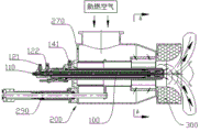
FIG. 1 is a schematic perspective view of a preferred embodiment of a flame adjustable burner for combustion of oxyhydrogen and fuel according to the present invention;
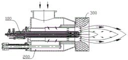
FIG. 2 is a schematic view of the rotary air flow regulating structure in a tangential combustion air entry position;
FIG. 3 is a schematic view of the rotary air flow regulating structure in a tangential combustion air entry position;
FIG. 4 is a schematic perspective view of a preferred embodiment of the oxyhydrogen gas and fuel mixing and spraying device according to the present invention;
FIG. 5 is a view showing an internal structure of the oxyhydrogen gas-fuel mixture injection apparatus shown in FIG. 4;
FIG. 6 is a detail drawing of the internal structure of FIG. 5;
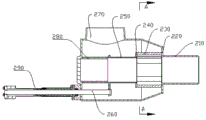
fig. 7 is a schematic perspective view of a preferred embodiment of the rotary airflow adjustment structure of the present invention;
FIG. 8 is a sectional view of the internal structure of the first state of the rotating airflow adjustment structure shown in FIG. 7;
FIG. 9 is a sectional view A-A of FIG. 8;
FIG. 10 is a sectional view of the internal structure of the second state of the rotating airflow adjustment structure shown in FIG. 7;
FIG. 11 is a cross-sectional view B-B of FIG. 10;
FIG. 12 is a schematic view of the mounting structure of the regulator of FIG. 7;
fig. 13 is a sectional view of the internal structure of the first state of another preferred embodiment of the rotary airflow adjusting structure of the present invention.
The parts in the drawings are numbered as follows:
100-oxyhydrogen gas and fuel mixed ejection device, 110-oxyhydrogen gas nozzle at the center, 111-center oxyhydrogen gas interface, 112-center oxyhydrogen gas channel, 113-center oxyhydrogen gas spray hole, 120-atomized fuel nozzle, 121-fuel interface, 122-compressed air interface, 123-fuel channel, 124-atomized gas channel, 125-fuel spray hole, 126-atomized gas spray hole, 127-atomized gas seal groove, 128-emulsified mixing chamber, 129-emulsified mixed solution spray hole, 130-movable adjusting device, 131-seal ring, 132-pressing sleeve, 133-left and right threaded joint, 134-guide rod, 140-oxyhydrogen gas nozzle at the outer side, 141-outer oxyhydrogen gas interface, 142-outer oxyhydrogen gas channel, 142-fuel nozzle at the center, oxygen gas nozzle at the outer side, oxygen gas nozzle at the center, oxygen gas spray hole, and fuel nozzle at the center, 143-outer hydrogen-oxygen jet hole; 200-rotary airflow adjusting structure, 210-air duct, 220-cyclone front cover, 230-blade, 240-cyclone rear cover, 250-adjusting spiral pipe, 260-connecting rod, 270-air inlet casing, 280-rear sleeve, 290-adjusting structure, 291-outer spiral pipe, 292-inner spiral pipe and 293-handle; 300-combustion nozzle.
Detailed Description
The following description of the embodiments of the present invention is provided for illustrative purposes, and other advantages and effects of the present invention will be readily apparent to those skilled in the art from the disclosure herein. The present invention can also be implemented or applied through other different specific embodiments, and various details in the present specification can be modified or changed based on different viewpoints and applications without departing from the spirit of the present invention.
Referring to fig. 1-13, it should be noted that the drawings provided in this embodiment illustrate the basic concept of the present invention, and the components in the drawings are drawn according to the number, shape and size of the components in practical implementation. The embodiment of the utility model provides an include:
as shown in fig. 1, a flame adjustable burner for combustion of oxyhydrogen gas and fuel comprises: oxyhydrogen gas and fuel mixture injection device 100, rotating airflow regulating structure 200, and combustion nozzle 300. The oxyhydrogen and fuel mixing and spraying device 100 is installed in the center of the burner, and the rotary airflow adjusting structure 200 is positioned on the concentric outer side of the oxyhydrogen and fuel mixing and spraying device 100 and is concentrically connected with the combustion nozzle 300 positioned at the front end. The combustion nozzle 300 has a function of stabilizing flame, and the combustion nozzle 300 is shaped like a bell mouth in the embodiment.
As shown in connection with fig. 2 and 3, the rotary airflow adjustment structure 200 is adjusted to have two positions by an adjuster: a combustion air tangential entry location and a combustion air radial entry location. As shown in fig. 2, the rotating airflow regulating structure 200 is located at the tangential entry position of the combustion air, and radial diffusion airflow is formed at the combustion nozzle 300, so that short flame is formed and flat flame is formed. As shown in FIG. 3, the rotating flow conditioning structure 200 is located at the combustion air radial entry location and the combustion ports 300 create an axial flow of air that creates a torch shaped long flame. The fuel which is combined with the oxyhydrogen gas for combustion is liquid fuel, can also be designed to be gas fuel, can also be designed to be powdery solid fuel, and can also be designed to be mixed with a plurality of fuels for use; convenient replacement and strong adaptability. The oxyhydrogen gas and fuel mixing and spraying device 100 improves the ignition performance of the fuel by utilizing the catalytic property of the oxyhydrogen gas, improves the burnout rate, reduces carbon black in the flue gas, and reduces the pollution of the combustion to the environment.
As shown in fig. 4, fig. 5 and fig. 6, the oxyhydrogen gas and fuel mixing and spraying device 100 for the flame adjustable burner using oxyhydrogen gas and fuel combined combustion of the present invention includes: a center position oxyhydrogen gas nozzle 110, an atomized fuel nozzle 120, a mobile adjusting device 130, and an outer position oxyhydrogen gas nozzle 140; the oxyhydrogen nozzle 110 at the center, the atomized fuel nozzle 120 and the oxyhydrogen nozzle at the outer side are integrated in a concentric sleeve manner. The center oxyhydrogen nozzle 110 in the embodiment is disposed at the coaxial center of the oxyhydrogen and fuel mixing and spraying device, and penetrates through the atomized fuel nozzle 120. The movement adjusting means 130 can move the hydrogen-oxygen gas nozzle 110 and the compressed air atomized fuel nozzle 120 in the center back and forth by rotating the left and right screw joints 131.
The oxyhydrogen nozzle 110 at the central position includes a central oxyhydrogen gas port 111, a central oxyhydrogen gas channel 112, and a central oxyhydrogen gas nozzle hole 113, the central oxyhydrogen gas port 111, the central oxyhydrogen gas channel 112, and the central oxyhydrogen gas nozzle hole 113 form a closed channel, the central oxyhydrogen gas channel 112 passes through the fuel nozzle 120 for atomizing compressed air, and the central oxyhydrogen gas nozzle hole 113 sprays oxyhydrogen gas, in this embodiment, the central oxyhydrogen gas nozzle hole 113 is made as a single hole.
In the embodiment shown, the atomized fuel nozzle 120 is a compressed air atomized fuel nozzle 120, and includes a fuel port 121, a fuel channel 123, a fuel nozzle 125, a compressed air port 122, a compressed air channel 124, a compressed air nozzle 126, an atomized air seal groove 127, an emulsion mixing chamber 128, and an emulsion mixture nozzle 129. The fuel interface 121, the fuel channel 123 and the fuel nozzle 125 form a fuel channel, and the fuel nozzle 125 is communicated with the emulsification mixing chamber 128. The compressed air interface 122, the compressed air passage 124 and the compressed air nozzle 126 form a compressed air passage, and the compressed air nozzle 126 is communicated with the emulsification mixing chamber 128. The specific process is as follows: fuel enters the emulsification mixing chamber 128 through the fuel interface 121, the fuel channel 123 and the fuel nozzle 125; meanwhile, compressed air enters the emulsifying and mixing chamber 128 through a compressed air interface 122, a compressed air channel 124 and a compressed air nozzle 126, and a seal labyrinth is formed by an atomizing air seal groove 127 at the front end of the compressed air channel. The fuel and the compressed air form an emulsified mixture in the emulsified mixture chamber 128 and are finally ejected through the emulsified mixture ejection hole 129. Alternatively, the emulsified mixed liquid injection hole 129 is formed as a coaxial divergent angle-halved hole. In the embodiment, the atomized fuel nozzle 120 with the internal mixing atomization spraying structure is shown, and the atomized fuel nozzle 120 may also adopt an external mixing atomization spraying structure, which is simpler and is not illustrated. Likewise, the atomized fuel nozzles 120 may be compressed air atomized fuel nozzles or steam atomized fuel nozzles.
The oxyhydrogen nozzle 140 at the outer position comprises an outer oxyhydrogen gas port 141, an outer oxyhydrogen gas channel 142 and outer oxyhydrogen gas nozzles 143, the outer oxyhydrogen gas port 141 and the outer oxyhydrogen gas channel 142 form a closed channel, and the oxyhydrogen gas is ejected through the outer oxyhydrogen gas nozzles 143. Alternatively, the outer hydrogen and oxygen injection holes 143 are formed as coaxial convergent angle equal holes and form a coaxial crossing angle with the emulsion mixture injection hole 129.
Referring to fig. 4, the oxyhydrogen gas and fuel mixing and spraying device of the present embodiment is a cylindrical structure as a whole, the nozzle (central oxyhydrogen gas nozzle 113) of the oxyhydrogen gas nozzle at the central position, the nozzle (outer oxyhydrogen gas nozzle 143) of the oxyhydrogen gas nozzle at the outer position, and the nozzle (emulsion mixture nozzle 129) of the atomized fuel nozzle are located at the front end, and the rear end is provided with a central oxyhydrogen gas port 111, a fuel port 121, a compressed air port 122, and an outer oxyhydrogen gas port 141, in the present embodiment, the central oxyhydrogen gas port 111 is located at the rear end face, and the fuel port 121, the compressed air port 122, and the outer oxyhydrogen gas port 141 are located in the lateral face in sequence. The movement adjusting device 3 is located between the compressed air port 122 and the outside oxyhydrogen gas port 141.
As shown in fig. 5 and 6, the movement adjusting device 130 includes a sealing ring 131, a pressing sleeve 132, left and right screw joints 133, and a guide rod 134. The clamping sleeve 132 is fitted over the atomized fuel nozzle 120. The sealing ring 131 is matched and sealed with the oxyhydrogen nozzle 140 and the compression sleeve 132 at the outer position, one end of the left and right screw joints 133 is connected with the compression sleeve 132, the other end of the left and right screw joints 133 is connected with the atomized fuel nozzle 120, one end of the guide rod 134 is connected with the atomized fuel nozzle 120, and the other end of the guide rod 134 is connected with the oxyhydrogen nozzle 140 at the outer position. Turning the left and right threaded connectors 133 during adjustment may retract or extend the distance between the compressed air atomized fuel nozzle 120 and the outer positioned oxyhydrogen nozzle 140.
The oxyhydrogen gas and fuel mixing and spraying device can ensure that the oxyhydrogen gas and fuels such as fuel, heavy oil and the like are mixed and sprayed in a grading way and then mixed with external combustion air to form a burner, and has the advantages of convenient installation, simple structure and safe and reliable combustion. By the method, the ignition performance of fuels such as fuel, heavy oil and the like can be improved by utilizing the characteristics of oxyhydrogen gas, and the burnout rate is improved. The fuel with high heat value and low price, such as fuel, heavy oil and the like, is fully utilized, the fuel cost is saved, the water vapor generated after the hydrogen and oxygen gas is combusted can catalyze carbon particles, the carbon black in the flue gas can be reduced, the pollutant emission is reduced, and the environmental protection pressure is reduced.
Referring to fig. 7 to 13, the rotary airflow adjusting structure 200 of the flame adjustable burner for oxyhydrogen and fuel combustion according to the present invention includes: air duct 210, cyclone, accent spiral ware, air inlet casing 270 and regulator.
The air inlet housing 270 includes an inner cavity, an air inlet and an air outlet, in this embodiment, the air inlet housing 270 is L-shaped, the air inlet is located at one end of the L-shaped, and the air outlet is located at the other end of the L-shaped.
The air duct 210 is located at the air outlet. The air outlet is the front end of the air inlet housing 270. The air duct 210 is an air outlet pipe and is connected with the cyclone front cover 220, and the direct current wind or the rotary wind formed by the rotary air flow adjusting structure is finally sprayed into the furnace through the air duct 210.
The cyclone is located in the internal cavity of the air inlet housing 270 and is connected with the air duct 210. The cyclone of this embodiment includes a cyclone front cover 220, a vane 230 and a cyclone rear cover 240, and the vane 230 is installed between the cyclone front cover 220 and the cyclone rear cover 240. As an example, the blades 230 are single bodies, 6 blades are uniformly distributed and installed in a forward direction, and the airflow is guided by the blades 230 to form a right-handed rotating wind. The cyclone back cover 240 has an inner diameter that is consistent with the inner contour of the vane 230 and is movably fitted with the outer diameter of the sealing section of the tuning coil 250.
Transfer the spiral ware to be located in the internal cavity, transfer the one end of spiral ware with the cyclone is connected, the other end with the rear end of air inlet casing 270 is connected. The rotation adjuster comprises a rotation adjusting pipe 250 and a rear sleeve 280, wherein the rear sleeve 280 is installed at the rear end of the inner cavity, and the tail end of the rear sleeve 280 is closed. The coil adjusting pipe 250 comprises a slotted section and a sealing section, and the slotted section of the coil adjusting pipe 250 is sleeved and connected with the rear sleeve 280; further preferably, the rear sleeve 280 is movably fitted to the inner diameter or the outer diameter of the slotted section of the tuning coil 250. The sealing section of the adjusting coil pipe 250 is connected with the cyclone rear cover 240, and the air duct 210 is connected with the cyclone front cover 220. As an example, the sealing section of the turning pipe 250 is a smooth pipe, and the grooved section of the turning pipe 250 is a pipe with 6 uniformly distributed grooves on the surface. As an example, the slotted equivalent cross-section of the slotted section of the tuning coil 250 is identical to the equivalent cross-section formed by the blades 230, and is shaped as a long slot. The adjuster adjusts the adjusting coil 250 to move back and forth between the rear sleeve 280 and the air duct 210, and in order to limit the displacement distance of the adjusting coil 250, the outer wall of the adjusting coil 250 in this embodiment has a convex structure and is located at the connection between the sealing section and the slotted section of the adjusting coil 250. As shown in fig. 4, when the tuning coil 250 is located at the front end, the protruding structure contacts the cyclone rear cover 240, and restricts the tuning coil 250 from moving forward.
The adjuster is connected with the adjusting coil 250, and the adjuster adjusts the forward and backward movement of the adjusting coil 250 between the rear sleeve 280 and the airway tube 210. Illustratively, the adjuster includes an adjustment structure 290 and a connecting rod 260. The adjusting structure 290 is located at the outer side 7 of the air intake casing and is connected with one end of the connecting rod 260. The other end of the connecting rod 260 is connected with the adjusting coil 250. As an example, in order to facilitate the connection with the connection rod 260, the outer wall of the tuning coil 250 has a protruding ear-shaped connection structure, and the connection rod 260 is connected with the ear-shaped connection structure, which is located at the connection position of the sealing section and the slotted section of the tuning coil 250.
Referring to fig. 12, the adjusting structure 290 is a screw rotation-to-linear pulling type, and is connected to the connecting rod 260 at the outer side of the air inlet housing 270. Specifically, the adjusting structure 290 includes an outer spiral pipe 291 and an inner spiral pipe 292, the front end of the outer spiral pipe 291 is fixed to the outside of the air intake casing 270, the front end of the inner spiral pipe 292 is connected to the rear end of the outer spiral pipe 291 through threads, the connecting rod 260 is sleeved on the outer spiral pipe 291 and the inner spiral pipe 292, the front end of the connecting rod 260 is connected to the adjusting spiral pipe 250, and the rear end of the connecting rod 260 is connected to the rear end of the inner spiral pipe 292. For the convenience of adjustment, the inner spiral tube 292 has a handle 293 at its rear end.
The action of the adjustment mechanism 290 shown in this embodiment is as follows: the connecting rod 260 can be driven to move forwards or backwards by rotating the handle 293 outside the adjusting structure 290, so that the adjusting coil 250 is linked to move forwards and backwards, and the airflow can be converted between the air inlet groove formed by the tangential blades and the straight groove at the rear end of the adjusting coil.
The action process of the rotary airflow adjusting structure in the embodiment is as follows: as shown in fig. 8 and 9, when the turning pipe 250 is located at the rear end, the cyclone is communicated with the air duct 210 to form a cyclone passage. Specifically, when the tuning coil 250 is located at the rear end, the slotted section of the tuning coil 250 is located at the rear sleeve 280, the straight slot of the slotted section is closed by the rear sleeve 280, and the air inlet slot formed by the tangential blades of the cyclone is opened. Thus, the airflow enters from the air inlet of the air inlet housing 270, flows through the air inlet grooves formed by the tangential blades of the cyclone, and finally is discharged from the air duct 210. Referring to fig. 10 and 11, when the coil adjusting pipe is located at the front end, the coil adjusting pipe is communicated with the air duct to form a direct wind channel. Specifically, when the tuning coil 250 is located at the front end, the grooved section of the tuning coil 250 exits the rear sleeve 280, the straight groove of the grooved section is opened, and the sealing section of the tuning coil 250 is located inside the cyclone, so that the air inlet groove formed by the tangential blades of the cyclone is closed. Thus, the air flow enters from the air inlet of the air inlet housing 270, flows through the straight groove of the grooved section of the turning pipe 250, enters the sealing section of the turning pipe 250, and finally is discharged from the air duct 210.
As shown in connection with fig. 13: the airflow rotational flow strength S formed by all the airflow at the tangential blades is greater than 1.3, and when a flared pipe is adopted at the outlet at the front end of the air duct 3, flat airflow can be formed.
In summary, it is shown that: the rotary airflow adjusting structure enables airflow in the air inlet shell to obtain stepless conversion from 100% direct current air to 100% rotary air at the outlet at the front end of the air guide pipe on the premise of not changing the air volume by the forward and backward movement of the adjusting coil pipe, and can obtain a required flame form in burner flame length adjustment. In addition, when the direct current wind and the rotating wind continuously change, the air flow in the furnace is disturbed, so that the fuel can be fully combusted, the heat utilization rate is improved, the uniformity of the furnace temperature is improved, and the heating quality is improved.
In the description of the present invention, it should be noted that the terms "upper", "lower", "left", "right", "inner", "outer", "front", and the like indicate the directions or positional relationships based on the directions or positional relationships shown in the drawings, or the directions or positional relationships that are conventionally placed when the products of the present invention are used, and are only for convenience of description and simplification of the description, but do not indicate or imply that the devices or elements indicated must have a specific direction, be constructed and operated in a specific direction, and thus, should not be construed as limiting the present invention.
Therefore, the utility model effectively overcomes various defects in the prior art and has high industrial utilization value. The above embodiments are merely illustrative of the principles and effects of the present invention, and are not to be construed as limiting the invention. Modifications and variations can be made to the above-described embodiments by those skilled in the art without departing from the spirit and scope of the present invention. Accordingly, it is intended that all equivalent modifications or changes which may be made by those skilled in the art without departing from the spirit and technical spirit of the present invention be covered by the claims of the present invention.
Claims (10)
1. The utility model provides an adjustable nozzle of flame that oxyhydrogen and fuel combine burning which characterized in that includes: the device comprises a oxyhydrogen and fuel mixing and spraying device, a rotary airflow adjusting structure and a combustion nozzle;
the rotary airflow adjusting structure comprises an air inlet shell, and a cyclone, a rotary adjuster and an adjuster which are connected in sequence, wherein the cyclone and the rotary adjuster are arranged in the air inlet shell;
the combustion nozzle is arranged at the air outlet of the air inlet shell; the cyclone, the rotation adjusting device and the combustion nozzle are communicated to form an air outlet channel;
the oxyhydrogen gas and fuel mixing and spraying device is arranged in the air outlet channel.
2. The adjustable flame burner of claim 1, wherein the fuel to be combusted in combination with oxyhydrogen gas is liquid fuel, gas fuel, solid fuel or a mixture of multiple fuels.
3. The adjustable flame burner for combustion of oxyhydrogen gas and fuel according to claim 1, wherein the combustion nozzle is in the shape of a bell mouth.
4. A flame adjustable burner for combined combustion of oxyhydrogen and fuel according to claim 1, wherein the rotary gas flow adjusting structure is adjusted by an adjuster to have two positions: a combustion air tangential entry location and a combustion air radial entry location.
5. The adjustable flame burner for combustion of oxyhydrogen and fuel according to claim 4, wherein the rotating airflow adjusting structure is located at the tangential entry position of combustion air, and radial diffusion airflow is formed at the combustion nozzle to form short flame and still flat flame.
6. The adjustable flame burner for combustion of oxyhydrogen gas and fuel according to claim 4, wherein the rotary airflow adjusting structure is located at the radial inlet position of combustion air, and the axial airflow is formed at the combustion nozzle to form a torch-shaped long flame.
7. The adjustable flame burner for combustion of oxyhydrogen and fuel according to claim 1, wherein the air intake housing comprises an internal cavity, an air intake and an air outlet; the air duct is positioned at the air outlet; the rotation adjusting device and the cyclone are positioned in the inner cavity, the rotation adjusting device comprises a rear sleeve and a rotation adjusting pipe, the rear sleeve is installed at the tail end of the inner cavity, the rotation adjusting pipe comprises a groove-opening section and a sealing section, and the groove-opening section of the rotation adjusting pipe is connected with the rear sleeve in a sleeved mode; one end of the cyclone is connected with the sealing section of the coil adjusting pipe, and the other end of the cyclone is connected with the air duct;
the regulator is connected with the adjusting coil pipe, and the adjusting coil pipe moves back and forth between the rear sleeve pipe and the air guide pipe; when the coil adjusting pipe is positioned at the rear end, the cyclone is communicated with the air duct to form a cyclone channel; when the adjusting coil pipe is positioned at the front end, the adjusting coil pipe is communicated with the air duct to form a direct wind channel.
8. The adjustable flame burner for combined combustion of oxyhydrogen and fuel according to claim 7, wherein the cyclone comprises a cyclone front cover, a cyclone rear cover and blades, the blades are installed between the cyclone front cover and the cyclone rear cover, the sealing section of the adjustable coil pipe is connected with the cyclone rear cover, and the air duct is connected with the cyclone front cover.
9. The adjustable flame burner for combined combustion of oxyhydrogen and fuel according to claim 7, wherein the regulator comprises a regulating structure and a connecting rod, the regulating structure is installed outside the air inlet casing, one end of the connecting rod is connected with the regulating structure, and the other end is connected with the regulating coil.
10. The adjustable flame burner with combined combustion of oxyhydrogen and fuel as claimed in claim 1, wherein the oxyhydrogen and fuel mixing and spraying device comprises a central oxyhydrogen nozzle, an atomized fuel nozzle and an outer oxyhydrogen nozzle, and the central oxyhydrogen nozzle, the atomized fuel nozzle and the outer oxyhydrogen nozzle are integrated in a concentric sleeve.
Applications Claiming Priority (2)
| Application Number | Priority Date | Filing Date | Title |
|---|---|---|---|
| CN202022310878 | 2020-10-16 | ||
| CN2020223108789 | 2020-10-16 |
Publications (1)
| Publication Number | Publication Date |
|---|---|
| CN214468603U true CN214468603U (en) | 2021-10-22 |
Family
ID=78148995
Family Applications (1)
| Application Number | Title | Priority Date | Filing Date |
|---|---|---|---|
| CN202022550522.2U Active CN214468603U (en) | 2020-10-16 | 2020-11-06 | Flame adjustable burner for combustion of hydrogen, oxygen and fuel |
Country Status (1)
| Country | Link |
|---|---|
| CN (1) | CN214468603U (en) |
-
2020
- 2020-11-06 CN CN202022550522.2U patent/CN214468603U/en active Active
Similar Documents
| Publication | Publication Date | Title |
|---|---|---|
| US4412808A (en) | Dual fueled burner gun | |
| JP5225110B2 (en) | Diesel engine fuel processing apparatus and method | |
| JPS6055721B2 (en) | Device that supplies a mixture of air and circulating combustion gas to the burner | |
| CN110260361A (en) | It is a kind of using metal powder as the after-burner of fuel | |
| CN113623653B (en) | Atmosphere-adjustable axial-cutting multistage cyclone ammonia-doped burner | |
| CN214468603U (en) | Flame adjustable burner for combustion of hydrogen, oxygen and fuel | |
| CN112344326A (en) | Flame adjustable burner for combustion of hydrogen, oxygen and fuel | |
| CN211424379U (en) | Diesel burner and burner thereof | |
| WO1987002756A1 (en) | Radiant tube burner | |
| CN115289473A (en) | Gas-powder dual-fuel burner | |
| CN107084388B (en) | Mixed atomization cracking burner and mixed combustion method thereof | |
| CN112963273B (en) | Self-air-entraining kerosene pre-combustion cracking activation device and method for concave cavity flame stabilizer | |
| CN212108382U (en) | Multi-nozzle air distribution low-nitrogen combustor | |
| CN211925749U (en) | Heat accumulating type burner | |
| RU61010U1 (en) | BURNER FOR LIQUID AND GAS FUEL COMBUSTION AND FUEL AND AIR SUPPLY SYSTEM | |
| CN210153776U (en) | Combustion head and alcohol-based low-nitrogen combustion device | |
| CN214700708U (en) | Low NOx combustor | |
| CA2167320A1 (en) | Apparatus and Method for Reducing NOx, CO and Hydrocarbon Emissions When Burning Gaseous Fuels | |
| CN112664978A (en) | Opposite-impact type cold flame combustion system | |
| CN112128761A (en) | Immersed low-nitrogen gas combustion device | |
| CN109737396A (en) | The low NO of multi-mode direct current staged air distribution fuel oilxCombustion method and its device | |
| CN205402707U (en) | Medium bubble atomizing heavy oil burner | |
| CN215489707U (en) | Burning gun for kiln | |
| CN112361337A (en) | Low NOx combustor | |
| CN212805643U (en) | Oxyhydrogen gas and BDO tar mix jetter |
Legal Events
| Date | Code | Title | Description |
|---|---|---|---|
| GR01 | Patent grant | ||
| GR01 | Patent grant |