CN214462412U - Construction platform with adjustable elevartor shaft - Google Patents
Construction platform with adjustable elevartor shaft Download PDFInfo
- Publication number
- CN214462412U CN214462412U CN202023295613.2U CN202023295613U CN214462412U CN 214462412 U CN214462412 U CN 214462412U CN 202023295613 U CN202023295613 U CN 202023295613U CN 214462412 U CN214462412 U CN 214462412U
- Authority
- CN
- China
- Prior art keywords
- supporting rod
- square frame
- platform
- rod
- construction platform
- Prior art date
- Legal status (The legal status is an assumption and is not a legal conclusion. Google has not performed a legal analysis and makes no representation as to the accuracy of the status listed.)
- Active
Links
Images


Abstract
The utility model provides a construction platform with adjustable elevartor shaft, includes square frame (1), its characterized in that: two medial surfaces that square frame (1) is relative serve and be provided with spout (8) of mutual symmetry respectively, install slide (9) in spout (8), slide (9) are articulated mutually with the one end of first branch (10), and the other end of first branch (10) is connected with the one end of second branch (11) through first activity pivot (14), square frame (1) is gone up and is connected with the one end of third branch (12) through fourth activity pivot (24), and the mid-mounting of bracing piece (19) has rotation seat (20), rotates and installs pneumatic cylinder (21) on seat (20), the utility model discloses rational in infrastructure, construction platform can go up and down wantonly in certain height range, and construction platform stability is good after going up and down to accomplish, has greatly made things convenient for the construction, and the efficiency of construction has obtained the improvement.
Description
Technical Field
The utility model relates to a construction platform especially relates to a construction platform with adjustable elevartor shaft, belongs to building construction equipment technical field.
Background
The elevator shaft is built in a multi-layer or high-rise building, the elevator shaft which is communicated up and down needs to be built in the construction process, the elevator shaft construction platform fully ensures the safety of constructors, and meanwhile, the operation of the constructors is convenient. Current elevartor shaft construction platform is mostly fixed structure, and construction platform's height is fixed, relies on tower crane or roof hoisting equipment to go on construction platform's lift completely, can only go on the successive layer to construction platform's lift moreover. The construction platform itself can't realize the lift of take the altitude, and the constructor still need the operation of ascending a height when carrying out same floor construction on the platform, has certain potential safety hazard, and the efficiency of construction is lower, lacks an effectual adjustable construction platform to solve this technical problem always.
Disclosure of Invention
The utility model aims at providing a current elevartor shaft construction platform is mostly fixed structure, construction platform itself can't realize the lift of a take the altitude, constructor still need the operation of ascending a height when carrying out the construction of same floor on the platform, the efficiency of construction is lower, use not too convenient defect and not enough, it is rational in infrastructure now to provide, construction platform can go up and down wantonly in certain altitude range, construction platform stability is good after going up and down to accomplish, greatly the construction of having made things convenient for, the efficiency of construction has obtained an elevartor shaft adjustable construction platform who improves.
In order to achieve the above object, the technical solution of the present invention is: the utility model provides a construction platform with adjustable elevartor shaft, includes square frame, its characterized in that: upright rods are symmetrically and vertically fixed on the left side and the right side of the lower part of one side of the square frame, a bottom cross rod is horizontally connected between the symmetrically arranged upright rods, limiting rods perpendicular to the upright rods are respectively fixed on the outer sides of the lower parts of the upright rods, the lower end of the other side of the square frame is connected with the lower ends of the upright rods through a triangular supporting rod, mutually symmetrical sliding grooves are respectively arranged at one ends of two opposite inner side surfaces of the square frame, sliding seats are arranged in the sliding grooves, the sliding seats are hinged with one end of a first supporting rod, the other end of the first supporting rod is connected with one end of a second supporting rod through a first movable rotating shaft, the other end of the second supporting rod is arranged on a sliding rail seat, the square frame is connected with one end of a third supporting rod through a fourth movable rotating shaft, the other end of the third supporting rod is connected with one end of a fourth supporting rod through a second movable rotating shaft, and a platform is arranged above the second supporting rod and the fourth supporting rod, the lower surface one side of platform is connected with the other end of fourth branch through the connecting axle, the lower surface opposite side of platform is fixed with the slide rail, install the slide rail seat on the slide rail, first branch middle part position is connected through fifth activity pivot with third branch middle part position, second branch middle part position is connected through sixth activity pivot with fourth branch middle part position, square frame or pole setting are improved level and are fixed with the bracing piece, the mid-mounting of bracing piece has the rotation seat, rotate and install the pneumatic cylinder on the seat, telescopic link on the pneumatic cylinder is articulated mutually with second branch or fourth branch.
Furthermore, a horizontal connecting rod is horizontally arranged between the two second supporting rods or the two fourth supporting rods through a third movable rotating shaft, and a telescopic rod on the hydraulic cylinder is connected with the middle position of the horizontal connecting rod.
Furthermore, the hydraulic cylinder is connected with a lifting controller or a hydraulic cylinder operating handle, and the lifting controller or the hydraulic cylinder operating handle is installed on the platform.
Furthermore, a pair of rollers is installed on the outer side of the triangular supporting rod through a roller seat, and the outer rim of each roller faces outwards.
Furthermore, a pair of adjustable screw rods is symmetrically arranged on the outer side surface of the square frame.
Furthermore, the outer edge of the upper surface of the square frame is symmetrically provided with hanging rings.
The utility model has the advantages that:
1. the utility model discloses a hydraulic pressure push rod and X type movable connecting rod support construction platform lets construction platform height can adjust, has made things convenient for constructor's construction, reduces the time waste because of constructor takes transport equipment of ascending a height and cause, and construction platform fixes on the support of bottom simultaneously, and the security has obtained the improvement during the construction.
2. The utility model discloses it is rational in infrastructure, realized that construction platform itself can go up and down wantonly in the take the altitude range, construction platform stability is good after going up and down to accomplish, has greatly made things convenient for the construction, and the efficiency of construction has obtained the improvement.
Drawings
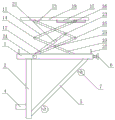
Fig. 1 is a schematic structural diagram of the present invention.
Fig. 2 is a front view of the present invention.
Fig. 3 is a schematic structural view of the support rod and the rotary seat portion of the present invention.
In the figure: the device comprises a square frame 1, a vertical rod 2, a bottom cross rod 3, a limiting rod 4, a triangular support rod 5, a screw 6, a roller 7, a sliding groove 8, a sliding seat 9, a first support rod 10, a second support rod 11, a third support rod 12, a fourth support rod 13, a first movable rotating shaft 14, a second movable rotating shaft 15, a sliding rail seat 16, a sliding rail 17, a platform 18, a support rod 19, a rotating seat 20, a hydraulic cylinder 21, a horizontal connecting rod 22, a third movable rotating shaft 23, a fourth movable rotating shaft 24, a fifth movable rotating shaft 25, a sixth movable rotating shaft 26 and a hanging ring 27.
Detailed Description
The invention is described in further detail below with reference to the following description of the drawings and the detailed description.
Referring to fig. 1 to 3, the utility model discloses a construction platform with adjustable elevartor shaft, including square frame 1, its characterized in that: upright rods 2 are symmetrically and vertically fixed on the left side and the right side of the lower part of one side of the square frame 1, a bottom cross rod 3 is horizontally connected between the symmetrically arranged upright rods 2, limiting rods 4 which are perpendicular to the upright rods 2 are respectively fixed on the outer sides of the lower parts of the upright rods 2, the lower end of the other side of the square frame 1 is connected with the lower ends of the upright rods 2 through a triangular supporting rod 5, mutually symmetrical sliding grooves 8 are respectively arranged at one ends of two opposite inner side surfaces of the square frame 1, sliding seats 9 are installed in the sliding grooves 8, the sliding seats 9 are hinged with one ends of first supporting rods 10, the other ends of the first supporting rods 10 are connected with one ends of second supporting rods 11 through first movable rotating shafts 14, the other ends of the second supporting rods 11 are installed on sliding rail seats 16, the square frame 1 is connected with one ends of third supporting rods 12 through fourth movable rotating shafts 24, and the other ends of the third supporting rods 12 are connected with one ends of fourth supporting rods 13 through second movable rotating shafts 15, a platform 18 is arranged above the second supporting rod 11 and the fourth supporting rod 13, one side of the lower surface of the platform 18 is connected with the other end of the fourth supporting rod 13 through a connecting shaft, a sliding rail 17 is fixed on the other side of the lower surface of the platform 18, a sliding rail seat 16 is installed on the sliding rail 17, the middle position of the first supporting rod 10 is connected with the middle position of the third supporting rod 12 through a fifth movable rotating shaft 25, the middle position of the second supporting rod 11 is connected with the middle position of the fourth supporting rod 13 through a sixth movable rotating shaft 26, a supporting rod 19 is horizontally fixed on the square frame 1 or the vertical rod 2, a rotating seat 20 is installed in the middle of the supporting rod 19, a hydraulic cylinder 21 is installed on the rotating seat 20, and a telescopic rod on the hydraulic cylinder 21 is hinged with the second supporting rod 11 or the fourth supporting rod 13.
A horizontal connecting rod 22 is horizontally arranged between the two second supporting rods 11 or the two fourth supporting rods 13 through a third movable rotating shaft 23, and a telescopic rod on the hydraulic cylinder 21 is connected with the middle position of the horizontal connecting rod 22.
The hydraulic cylinder 21 is connected with a lifting controller or a hydraulic cylinder operating handle, and the lifting controller or the hydraulic cylinder operating handle is installed on the platform 18.
The outer side of the triangular supporting rod 5 is provided with a pair of rollers 7 through a roller seat, and the outer side wheel rim of each roller 7 faces outwards.
A pair of adjustable screw rods 6 is symmetrically arranged on the outer side surface of the square frame 1.
The outer edge of the upper surface of the square frame 1 is symmetrically provided with hanging rings 27.
As shown in fig. 1 to 3, a square frame 1 is formed by welding four support rods, the left side and the right side of one support rod of the square frame 1 are respectively and vertically fixed with a vertical rod 2, screw rods 6 are symmetrically arranged on the outer side surface of the other support rod parallel to the vertical rod 2 on the square frame 1, when a construction platform is positioned in an elevator shaft, the construction platform is clamped in the elevator shaft by a limiting rod 4 and the screw rods 6, and when the square frame 1 is not inclined on a horizontal plane, the square frame can be adjusted to be in a horizontal state by adjusting the length of the square frame 1 by screwing the adjusting screw rods 6 out. The two opposite supporting rods of the square frame 1 are symmetrically provided with hanging rings 27 respectively, so that a construction platform can be hung by a hanging tower hook through the hanging rings 27 conveniently, when the construction platform is lifted upwards through a hanging tower, the screw 6 is screwed out of the square frame 1 to be shortest in length, the front transverse length and the rear transverse length of the construction platform in an elevator shaft are shortest, and the construction platform can be lifted upwards conveniently. In order to facilitate the transportation of the construction platform, a pair of rollers 7 is fixedly arranged on the triangular support rod 5 arranged between the upright rod 2 and the square frame 1.
The inner sides of the parallel supporting rods on the square frame 1 are respectively provided with a sliding groove 8, a sliding seat 9 is arranged on the sliding groove 8, and the sliding seat 9 is hinged with one end of a first supporting rod 10. One end of the first supporting rod 10 can rotate on the sliding seat 9 through an articulated shaft, the other end and one end of the second supporting rod 11 can rotate mutually through a first movable rotating shaft 14, the other end of the second supporting rod 11 is installed on a sliding rail seat 16 through a rotating shaft, and the second supporting rod 11 can rotate on the sliding rail seat 16 through the rotating shaft. One end of the third supporting rod 12 rotates on the square frame 1 through the fourth movable rotating shaft 24, the other end of the third supporting rod rotates with one end of the fourth supporting rod 13 through the second movable rotating shaft 15, and the other end of the fourth supporting rod 13 can rotate on the lower surface of the platform 18 through the connecting shaft. A slide rail 17 is fixed on the other side of the lower surface of the platform 18, a slide rail seat 16 is installed on the slide rail 17, and the second support rod 11 slides on the slide rail 17 through the slide rail seat 16.
The middle position of the first supporting rod 10 and the middle position of the third supporting rod 12 rotate mutually through a fifth movable rotating shaft 25, and the middle position of the second supporting rod 11 and the middle position of the fourth supporting rod 13 rotate mutually through a sixth movable rotating shaft 26. One end of a hydraulic pump 21 is fixed on a support rod 19 between the upright rods 2 through a rotating seat 20, the support rod 19 can also be fixed between mutually parallel support rods of the square frame 1, and one end of a hydraulic cylinder 21 rotates on the support rod 19 through the rotating seat 20. The push rod at the other end of the hydraulic cylinder 21 can rotate at the middle position of the horizontal connecting rod 22 through a third movable rotating shaft 23. The hydraulic cylinder 21 may be an electric hydraulic cylinder connected to a lift button box provided on the platform 18, or a mechanical hydraulic cylinder having an operating handle provided on the platform 18.
The construction platform is pushed to an elevator well mouth through the idler wheel 7, the construction platform is hung and placed in an elevator shaft through the hoisting tower, and the construction surface of the construction platform is adjusted to be in a horizontal state by the length of the adjusting screw 6 extending out of the square frame 1. When the hydraulic pump 21 is an electric hydraulic pump, a lift button provided on the platform 18 is pressed, and a push rod of the hydraulic pump 21 pushes the horizontal connecting rod 22 to move upward. The first support rod 10, the second support rod 11, the third support rod 12, the fourth support rod 13, the first movable rotating shaft 14, the second movable rotating shaft 15, the fifth movable rotating shaft 25 and the sixth movable rotating shaft 26 are combined together to form two groups of superposed X-shaped support structures. In the process that the push rod of the hydraulic cylinder 21 pushes the horizontal connecting rod 22 to move upwards, the X-shaped support structure is supported upwards, and one end of the first supporting rod 10 rotates on the sliding seat 9 and drives the sliding seat 9 to horizontally move towards one end of the third support in the sliding groove 8; one end of the second support rod 11 rotates on the slide rail seat 16, and simultaneously drives the slide rail seat 16 to horizontally move towards one end of the fourth support rod 13 on the slide rail 17. X type supporting structure progressively changes from folding the horizontal condition into propping up the vertical condition like this, promotes platform 18 progressively upward movement to make things convenient for constructor construction, reduced because of constructor takes the time waste that transport equipment of ascending a height caused, platform 18 fixes on the bottom support through X type supporting structure simultaneously, and constructor stands and can be more firm on platform 18, safer.
A descending button arranged on the platform 18 is pressed, a push rod of a hydraulic cylinder 21 pulls a horizontal connecting rod 22 to move downwards, the X-shaped support structure is folded downwards, and one end of a first supporting rod 10 rotates on the sliding seat 9 and simultaneously drives the sliding seat 9 to horizontally move towards the opposite direction of one end of a third support in the sliding groove 8; one end of the second support rod 11 rotates on the slide rail seat 16, and simultaneously drives the slide rail seat 16 to horizontally move on the slide rail 17 in the opposite direction to one end of the fourth support rod 13. The X-shaped frame structure is thus gradually transformed from an erected vertical position to a folded horizontal position, pulling the movable platform 18 gradually downwards.
The X-shaped support structure can be formed by combining one or more groups of X-shaped supports, the lifting height of the X-shaped support structure supporting platform 18 can be set to be the height of a two-layer floor, and a constructor can construct two layers and then upwards improve the construction platform through the tower crane, so that the number of times of lifting the height of the construction platform through the tower crane can be reduced, and the construction efficiency is improved.
The above description is for further details of the present invention, and the detailed implementation of the present invention is not limited to these descriptions, and for those skilled in the art to which the present invention pertains, the present invention can be easily replaced, modified and changed without departing from the inventive concept of the present invention, and all of the simple replacements, modifications and changes should be considered as belonging to the protection scope of the present invention.
Claims (6)
1. The utility model provides a construction platform with adjustable elevartor shaft, includes square frame (1), its characterized in that: the utility model discloses a square frame (1) is characterized in that one side lower part left and right sides symmetry vertical fixation of square frame (1) has pole setting (2), and horizontally connect has bottom horizontal pole (3) between the pole setting (2) that the symmetry set up, and the lower part outside of pole setting (2) is fixed with respectively with pole setting (2) looks vertically gag lever post (4), is connected through triangular support pole (5) between the opposite side lower extreme of square frame (1) and the lower extreme of pole setting (2), be provided with spout (8) of mutual symmetry on two relative medial surfaces one end of square frame (1) respectively, install slide (9) in spout (8), slide (9) are articulated mutually with the one end of first branch (10), and the other end of first branch (10) is connected through the one end of first activity pivot (14) with second branch (11), and the other end of second branch (11) is installed on slide rail seat (16), the one end looks of square frame (1) through fourth activity pivot (24) and third branch (12) is gone up The other end of the third supporting rod (12) is connected with one end of the fourth supporting rod (13) through a second movable rotating shaft (15), a platform (18) is arranged above the second supporting rod (11) and the fourth supporting rod (13), one side of the lower surface of the platform (18) is connected with the other end of the fourth supporting rod (13) through a connecting shaft, a sliding rail (17) is fixed on the other side of the lower surface of the platform (18), a sliding rail seat (16) is installed on the sliding rail (17), the middle position of the first supporting rod (10) is connected with the middle position of the third supporting rod (12) through a fifth movable rotating shaft (25), the middle position of the second supporting rod (11) is connected with the middle position of the fourth supporting rod (13) through a sixth movable rotating shaft (26), a supporting rod (19) is horizontally fixed on the square frame (1) or the vertical rod (2), and a rotating seat (20) is installed in the middle of the supporting rod (19), a hydraulic cylinder (21) is arranged on the rotating seat (20), and a telescopic rod on the hydraulic cylinder (21) is hinged with the second supporting rod (11) or the fourth supporting rod (13).
2. The construction platform with adjustable elevator shaft of claim 1, characterized in that: a horizontal connecting rod (22) is horizontally arranged between the two second supporting rods (11) or the two fourth supporting rods (13) through a third movable rotating shaft (23), and a telescopic rod on the hydraulic cylinder (21) is connected with the middle position of the horizontal connecting rod (22).
3. The construction platform with adjustable elevator shaft of claim 1, characterized in that: the hydraulic cylinder (21) is connected with a lifting controller or a hydraulic cylinder operating handle, and the lifting controller or the hydraulic cylinder operating handle is installed on the platform (18).
4. The construction platform with adjustable elevator shaft of claim 1, characterized in that: a pair of rollers (7) is installed on the outer side of the triangular supporting rod (5) through a roller seat, and the outer rim of each roller (7) faces outwards.
5. The construction platform with adjustable elevator shaft of claim 1, characterized in that: and a pair of adjustable screw rods (6) is symmetrically arranged on the outer side surface of the square frame (1).
6. The construction platform with adjustable elevator shaft of claim 1, characterized in that: and the outer edge of the upper surface of the square frame (1) is symmetrically provided with hanging rings (27).
Priority Applications (1)
| Application Number | Priority Date | Filing Date | Title |
|---|---|---|---|
| CN202023295613.2U CN214462412U (en) | 2020-12-31 | 2020-12-31 | Construction platform with adjustable elevartor shaft |
Applications Claiming Priority (1)
| Application Number | Priority Date | Filing Date | Title |
|---|---|---|---|
| CN202023295613.2U CN214462412U (en) | 2020-12-31 | 2020-12-31 | Construction platform with adjustable elevartor shaft |
Publications (1)
| Publication Number | Publication Date |
|---|---|
| CN214462412U true CN214462412U (en) | 2021-10-22 |
Family
ID=78136114
Family Applications (1)
| Application Number | Title | Priority Date | Filing Date |
|---|---|---|---|
| CN202023295613.2U Active CN214462412U (en) | 2020-12-31 | 2020-12-31 | Construction platform with adjustable elevartor shaft |
Country Status (1)
| Country | Link |
|---|---|
| CN (1) | CN214462412U (en) |
-
2020
- 2020-12-31 CN CN202023295613.2U patent/CN214462412U/en active Active
Similar Documents
| Publication | Publication Date | Title |
|---|---|---|
| CN201286669Y (en) | Folding type window cleaning device | |
| CN105507572B (en) | The scaffold that can be walked | |
| CN212359051U (en) | Electric power high altitude construction auxiliary device | |
| CN203559575U (en) | Adjustable suspended platform for slope | |
| CN215558710U (en) | Adjustable track traction erection device for bridge construction | |
| CN214462412U (en) | Construction platform with adjustable elevartor shaft | |
| CN108002249A (en) | Substation equipment maintenance and repair small space boom hoisting | |
| CN205472146U (en) | Organic tenant's ladder sedan -chair frame | |
| CN202072413U (en) | Lifting frame | |
| CN214734124U (en) | Foldable detachable lifting platform | |
| CN202899589U (en) | Foldable lifting scaffold | |
| CN110259095A (en) | A kind of folding high-altitude lift work stage apparatus | |
| CN214995818U (en) | Climbing type construction operation platform outside building | |
| CN214659903U (en) | A cat ladder for safety engineering | |
| CN209259612U (en) | A kind of feeding device for construction | |
| CN114059913A (en) | Auxiliary platform for on-column equipment maintenance | |
| CN217079583U (en) | Scaffold frame for house construction with adjustable | |
| CN206667048U (en) | A kind of bridge inspection vehicle | |
| CN206634993U (en) | A kind of indoor lifting frame for building | |
| CN219259406U (en) | Pulling device for steel structure roof truss | |
| CN217439486U (en) | Scaffold for building construction for preventing slope collapse | |
| CN212715842U (en) | Scaffold for building construction | |
| CN216305345U (en) | Variable hanging basket for house construction engineering | |
| CN205527461U (en) | Large -scale experimental facilities hoisting machine that can fold up constructs | |
| CN217431977U (en) | Gypsum cyclone separation device |
Legal Events
| Date | Code | Title | Description |
|---|---|---|---|
| GR01 | Patent grant | ||
| GR01 | Patent grant |