CN214392050U - Precision stamping device is used in sheet metal component processing - Google Patents
Precision stamping device is used in sheet metal component processing Download PDFInfo
- Publication number
- CN214392050U CN214392050U CN202023007546.XU CN202023007546U CN214392050U CN 214392050 U CN214392050 U CN 214392050U CN 202023007546 U CN202023007546 U CN 202023007546U CN 214392050 U CN214392050 U CN 214392050U
- Authority
- CN
- China
- Prior art keywords
- feeding
- driving
- sheet metal
- stamping
- face
- Prior art date
- Legal status (The legal status is an assumption and is not a legal conclusion. Google has not performed a legal analysis and makes no representation as to the accuracy of the status listed.)
- Active
Links
Images


Abstract
The utility model provides an accurate stamping device for sheet metal component processing, including stamping head, fixed frame, electric telescopic handle, feeding box, bearing plate, driving pulley, driving belt, driven pulley, driving motor, initiative feeding roller and material loading roof, the stamping head is installed on the upper side of the fixed frame, the bearing plate is installed on the upper side of the left end face of the fixed frame, the feeding box is installed on the upper side of the bearing plate, the electric telescopic handle is installed on the left side of the feeding box, the material loading roof is installed on the right end face of the electric telescopic handle, the driving motor is installed on the lower end face of the bearing plate, the driving pulley is installed on the front side of the driving motor, the initiative feeding roller is installed on the right side of the feeding box, the driven pulley is installed on the front side of the initiative feeding roller, the driving belt is installed between the driving pulley and the driven pulley in a connecting manner, the design solves the problem that the manual feeding speed of the accurate stamping device for sheet metal component processing is slower, the utility model discloses rational in infrastructure, be convenient for carry out quick material loading operation to the work piece, machining efficiency is high.
Description
Technical Field
The utility model relates to a sheet metal component processing is with accurate stamping device belongs to sheet metal component processing equipment technical field.
Background
The stamping is a forming method in which a press and a die are used to apply external force to a plate, a strip, a pipe, a profile, etc. to cause plastic deformation or separation, thereby obtaining a workpiece (stamped part) of a desired shape and size. Stamping and forging are plastic working (or called pressure working), and are called forging and pressing. The stamping is a production technology which makes the plate directly receive deformation force and deform in a die by the power of conventional or special stamping equipment, thereby obtaining product parts with certain shape, size and performance. The plate, the die and the equipment are three elements of stamping processing. The hot stamping and the cold stamping are divided according to the stamping processing temperature. The former is suitable for processing sheet materials with high deformation resistance and poor plasticity; the latter is carried out at room temperature and is a common stamping method for thin sheets. It is one of the main methods of metal plastic working (or pressure working), and also belongs to the material forming engineering technology.
Among the prior art, current precision stamping device for sheet metal component processing is carrying out the in-process of processing to the work piece, carries out manual material loading by the staff usually, and this kind of material loading mode speed is slower, and material loading efficiency is lower, has increased workman's intensity of labour, and stamping process efficiency is lower, and the problem that above-mentioned appearance is solved to the precision stamping device for sheet metal component processing that now urgently needs.
SUMMERY OF THE UTILITY MODEL
The utility model aims at providing a not enough to prior art exists, the utility model aims at providing an accurate stamping device is used in sheet metal component processing to solve the problem that proposes in the above-mentioned background art, the utility model discloses rational in infrastructure is convenient for carry out quick material loading operation to the work piece, and machining efficiency is high.
In order to achieve the above purpose, the present invention is realized by the following technical solution: a precision stamping device for sheet metal part machining comprises a convenient feeding mechanism, a stamping machine head, a stamping rod, a stamping plate, a stamping die, a fixed machine base and a supporting foot pad, wherein the supporting foot pad is installed on the lower side of the fixed machine base, the stamping die is installed on the upper side of the fixed machine base, the stamping machine head is installed on the upper side of the fixed machine base, the stamping rod is installed inside the stamping machine head, the stamping plate is installed on the lower side of the stamping rod, the convenient feeding mechanism is arranged on the left side of the fixed machine base and comprises an electric telescopic rod, a feeding box, a supporting plate, a driving belt wheel, a transmission belt, a driven belt wheel, a driving motor, a driving feeding roller and a feeding top plate, the supporting plate is installed on the upper side of the left end face of the fixed machine base, the feeding box is installed on the upper side of the supporting plate, the electric telescopic rod is installed on the left side of the feeding box, the feeding top plate is installed on the right end face of the electric telescopic rod, the automatic feeding device is characterized in that a driving motor is installed on the lower end face of the supporting plate, a driving belt wheel is installed on the front side of the driving motor, a driving feeding roller is installed on the right side of the feeding box, a driven belt wheel is installed on the front side of the driving feeding roller, and a transmission belt is installed between the driving belt wheel and the driven belt wheel in a connected mode.
Furthermore, the electric telescopic rod and the driving motor are connected with an external power supply through wires.
Furthermore, a reinforcing rib plate is arranged at the joint of the bearing plate and the fixed base, the reinforcing rib plate is of a triangular structure, and the reinforcing rib plate is fixedly connected with the bearing plate and the fixed base in a welding mode.
Further, driven material loading roller is arranged on the right side of the driving material loading roller, the specification of the driven material loading roller is the same as that of the driving material loading roller, and the tangent line on the upper side of the annular side face of the driving material loading roller and the annular side face of the driven material loading roller are flush with the upper end face of the stamping die.
Further, the left end face of the electric telescopic rod is provided with a fixing plate.
Further, the sheet metal workpiece is placed inside the feeding box, and the specification of the feeding box is matched with that of the sheet metal workpiece.
Furthermore, a feeding groove opening is formed in the inner portion of the left end face of the feeding box, the position of the feeding groove opening corresponds to that of the feeding top plate, and the width of the feeding groove opening is slightly larger than the thickness of the feeding top plate.
The utility model has the advantages that: the utility model discloses an accurate stamping device is used in sheet metal component processing, because of the utility model discloses added electric telescopic handle, go up workbin, bearing plate, driving pulley, driving belt, driven pulley, driving motor, initiative material loading roller and material loading roof, this design can carry out quick material loading operation to the work piece, has solved the slower problem of the artifical material loading speed of accurate stamping device for original sheet metal component processing, has improved the processing efficiency of the utility model.
Because the electric telescopic rod and the driving motor are connected with an external power supply through wires, the design is convenient for carrying out electric control on the electric telescopic rod and the driving motor through the external power supply, because the reinforcing rib plate is arranged at the joint of the bearing plate and the fixed machine base, the reinforcing rib plate is of a triangular structure and is fixedly connected with the bearing plate and the fixed machine base in a welding way, the design improves the structural supporting strength of the joint of the supporting plate and the fixed base through the reinforcing rib plate, because the driven feeding roller is arranged on the right side of the driving feeding roller, the specification of the driven feeding roller is the same as that of the driving feeding roller, the tangent line on the upper side of the annular side surface of the driving feeding roller and the driven feeding roller is flush with the upper end surface of the stamping die, this design has improved the material loading speed to the work piece through driven material loading roller, the utility model discloses rational in infrastructure, be convenient for carry out quick material loading operation to the work piece, machining efficiency is high.
Drawings
Other features, objects and advantages of the invention will become more apparent upon reading of the detailed description of non-limiting embodiments with reference to the following drawings:
fig. 1 is a schematic structural view of a precision stamping device for sheet metal part processing according to the present invention;
FIG. 2 is a schematic structural view of a mechanism for facilitating feeding in a precision stamping apparatus for sheet metal part processing according to the present invention;
FIG. 3 is a front sectional view of a feeding mechanism of the precision press for sheet metal part processing of the present invention;
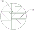
FIG. 4 is an enlarged view of A in FIG. 3;
in the figure: 1-convenient feeding mechanism, 2-punching machine head, 3-punching rod, 4-punching plate, 5-punching die, 6-fixed machine base, 7-supporting foot pad, 11-electric telescopic rod, 12-feeding box, 13-supporting plate, 14-driving belt wheel, 15-driving belt, 16-driven belt wheel, 17-driving motor, 18-driving feeding roller, 19-feeding top plate, 111-fixed plate, 121-sheet metal workpiece, 131-reinforcing plate, 181-driven feeding roller and 191-feeding notch.
Detailed Description
In order to make the technical means, creation features, achievement purposes and functions of the present invention easy to understand, the present invention is further described below with reference to the following embodiments.
Referring to fig. 1-4, the present invention provides a technical solution: the utility model provides a precision stamping device is used in sheet metal component processing, including the feed mechanism 1 of being convenient for, stamping head 2, stamping rod 3, punching press board 4, stamping die 5, fixed frame 6 and support callus on the sole 7, 6 downside of fixed frame are installed and are supported callus on the sole 7, stamping die 5 is installed to 6 upsides of fixed frame, stamping head 2 is installed to 6 upsides of fixed frame, 2 internally mounted stamping head have stamping rod 3, punching press board 4 is installed to 3 downside of stamping rod, 6 left sides of fixed frame are provided with the feed mechanism 1 of being convenient for.
It includes electric telescopic handle 11 to be convenient for feed mechanism 1, go up workbin 12, bearing plate 13, driving pulley 14, driving belt 15, driven pulleys 16, driving motor 17, driving material loading roller 18 and material loading roof 19, bearing plate 13 is installed to 6 left end face upsides of fixed frame, material loading box 12 is installed to the bearing plate 13 upside, electric telescopic handle 11 is installed in material loading box 12 left side, material loading roof 19 is installed to electric telescopic handle 11 right-hand member face, driving motor 17 is installed to the terminal surface under the bearing plate 13, driving pulley 14 is installed to driving motor 17 front side, driving material loading roller 18 is installed on material loading box 12 right side, driven pulleys 16 are installed to driving material loading roller 18 front side, driving belt 15 is installed to the connection between driving pulley 14 and the driven pulleys 16, this design has solved the slower problem of the artifical material loading speed of original precision stamping device for sheet metal parts processing.
Electric telescopic handle 11 and driving motor 17 are connected with the external power supply through the wire, this design is convenient for carry out electric control to electric telescopic handle 11 and driving motor 17 through the external power supply, bearing plate 13 is provided with deep floor 131 with fixed frame 6 junction, deep floor 131 is the triangle-shaped structure, deep floor 131 carries out fixed connection with bearing plate 13 and fixed frame 6 through the welding mode, this design has improved the structure bearing strength of bearing plate 13 with fixed frame 6 junction through deep floor 131, initiative material loading roller 18 right side is provided with driven material loading roller 181, driven material loading roller 181 specification is the same with initiative material loading roller 18 specification, initiative material loading roller 18 flushes with stamping die 5 up end with driven material loading roller 181 annular side upside, this design has improved the material loading speed to the work piece through driven material loading roller 181.
11 left end faces of electric telescopic handle are provided with fixed plate 111, this design is convenient for install electric telescopic handle 11 fixedly through fixed plate 111, the inside panel beating work piece 121 of having placed of material loading case 12, 12 specifications of material loading case and panel beating work piece 121 specification phase-match, the rationality of this design has been improved, material loading notch 191 has been seted up to material loading case 12 left end face inside, material loading notch 191 position is corresponding with material loading roof 19 position, material loading notch 191 width slightly is greater than material loading roof 19 thickness, this design is convenient for make material loading roof 19 carry out the top loading through material loading notch 191 and is handled panel beating work piece 121.
As an embodiment of the present invention: the working personnel firstly connect the electric telescopic rod 11 and the driving motor 17 with an external power supply through wires, then put the sheet metal workpiece 121 into the feeding box 12, then start the electric telescopic rod 11 and the driving motor 17 through the external power supply, the electric telescopic rod 11 is electrified and extends towards the right side, the feeding top plate 19 is driven by the electric telescopic rod 11 to move towards the right side, the feeding top plate 19 is inserted into the feeding box 12 through the feeding slot 191, the sheet metal workpiece 121 in the feeding box 12 is pushed towards the right side by the right movement of the feeding top plate 19, the sheet metal workpiece 121 is pushed out of the feeding box 12, the sheet metal workpiece 121 falls on the upper side of the driving feeding roller 18, the driving motor 17 drives the driving pulley 14 to rotate, the driving pulley 14 is rotationally connected with the driven pulley 16 on the front side of the driving feeding roller 18 through the transmission belt 15, further drives the driven pulley 16 to rotate, the driving feeding roller 18 is driven by the driven pulley 16 to rotate, the driving feeding roller 18 rotates to convey the sheet metal workpiece 121 to the right side, so that the sheet metal workpiece 121 is in contact with the driven feeding roller 181, the sheet metal workpiece 121 is conveyed to the stamping die 5 through the driving feeding roller 18 and the driven feeding roller 181, then the sheet metal workpiece 121 is stamped through the stamping plate 4, and the feeding efficiency of the sheet metal workpiece 121 is improved.
The basic principles and the main features of the invention and the advantages of the invention have been shown and described above, it will be evident to those skilled in the art that the invention is not limited to the details of the foregoing illustrative embodiments, but that the invention may be embodied in other specific forms without departing from the spirit or essential characteristics of the invention. The present embodiments are therefore to be considered in all respects as illustrative and not restrictive, the scope of the invention being indicated by the appended claims rather than by the foregoing description, and all changes which come within the meaning and range of equivalency of the claims are therefore intended to be embraced therein. Any reference sign in a claim should not be construed as limiting the claim concerned.
Furthermore, it should be understood that although the present description refers to embodiments, not every embodiment may contain only a single embodiment, and such description is for clarity only, and those skilled in the art should integrate the description, and the embodiments may be combined as appropriate to form other embodiments understood by those skilled in the art.
Claims (7)
1. The utility model provides a sheet metal component processing is with accurate stamping device, includes the feed mechanism, punching press aircraft nose, stamping rod, punching press board, stamping die, solid fixed frame and the support callus on the sole of being convenient for, its characterized in that: the stamping die is mounted on the upper side of the fixed base, a stamping head is mounted on the upper side of the fixed base, a stamping rod is mounted inside the stamping head, a stamping plate is mounted on the lower side of the stamping rod, and a feeding mechanism is arranged on the left side of the fixed base;
the convenient feeding mechanism comprises an electric telescopic rod, a feeding box, a supporting plate, a driving belt wheel, a transmission belt, a driven belt wheel, a driving motor, a driving feeding roller and a feeding top plate, wherein the supporting plate is installed on the upper side of the left end face of the fixed base, the feeding box is installed on the upper side of the supporting plate, the electric telescopic rod is installed on the left side of the feeding box, the feeding top plate is installed on the right end face of the electric telescopic rod, the driving motor is installed on the lower end face of the supporting plate, the driving belt wheel is installed on the front side of the driving motor, the driving feeding roller is installed on the right side of the feeding box, the driven belt wheel is installed on the front side of the driving feeding roller, and the transmission belt is installed between the driving belt wheel and the driven belt wheel.
2. The precision stamping device for sheet metal part machining according to claim 1, characterized in that: the electric telescopic rod and the driving motor are connected with an external power supply through wires.
3. The precision stamping device for sheet metal part machining according to claim 1, characterized in that: the bearing plate is characterized in that a reinforcing rib plate is arranged at the joint of the bearing plate and the fixed base, the reinforcing rib plate is of a triangular structure, and the reinforcing rib plate is fixedly connected with the bearing plate and the fixed base in a welding mode.
4. The precision stamping device for sheet metal part machining according to claim 1, characterized in that: the driven feeding roller is arranged on the right side of the driving feeding roller, the specification of the driven feeding roller is the same as that of the driving feeding roller, and the tangent line on the upper side of the annular side face of the driving feeding roller and the annular side face of the driven feeding roller are flush with the upper end face of the stamping die.
5. The precision stamping device for sheet metal part machining according to claim 1, characterized in that: the left end face of the electric telescopic rod is provided with a fixing plate.
6. The precision stamping device for sheet metal part machining according to claim 1, characterized in that: the sheet metal workpiece is placed in the feeding box, and the specification of the feeding box is matched with that of the sheet metal workpiece.
7. The precision stamping device for sheet metal part machining according to claim 1, characterized in that: the feeding box is characterized in that a feeding groove opening is formed in the left end face of the feeding box, the position of the feeding groove opening corresponds to that of the feeding top plate, and the width of the feeding groove opening is slightly larger than the thickness of the feeding top plate.
Priority Applications (1)
| Application Number | Priority Date | Filing Date | Title |
|---|---|---|---|
| CN202023007546.XU CN214392050U (en) | 2020-12-15 | 2020-12-15 | Precision stamping device is used in sheet metal component processing |
Applications Claiming Priority (1)
| Application Number | Priority Date | Filing Date | Title |
|---|---|---|---|
| CN202023007546.XU CN214392050U (en) | 2020-12-15 | 2020-12-15 | Precision stamping device is used in sheet metal component processing |
Publications (1)
| Publication Number | Publication Date |
|---|---|
| CN214392050U true CN214392050U (en) | 2021-10-15 |
Family
ID=78038253
Family Applications (1)
| Application Number | Title | Priority Date | Filing Date |
|---|---|---|---|
| CN202023007546.XU Active CN214392050U (en) | 2020-12-15 | 2020-12-15 | Precision stamping device is used in sheet metal component processing |
Country Status (1)
| Country | Link |
|---|---|
| CN (1) | CN214392050U (en) |
Cited By (1)
| Publication number | Priority date | Publication date | Assignee | Title |
|---|---|---|---|---|
| CN115283599A (en) * | 2022-08-03 | 2022-11-04 | 桐乡市桐诚科技有限公司 | Pressing device for production of textile machine sinker and use method thereof |
-
2020
- 2020-12-15 CN CN202023007546.XU patent/CN214392050U/en active Active
Cited By (1)
| Publication number | Priority date | Publication date | Assignee | Title |
|---|---|---|---|---|
| CN115283599A (en) * | 2022-08-03 | 2022-11-04 | 桐乡市桐诚科技有限公司 | Pressing device for production of textile machine sinker and use method thereof |
Similar Documents
| Publication | Publication Date | Title |
|---|---|---|
| CN214392050U (en) | Precision stamping device is used in sheet metal component processing | |
| CN107838360A (en) | Automatic riveting machine | |
| CN112059401A (en) | Friction stir welding pressing device and method | |
| CN213002076U (en) | Stamping die who facilitates use | |
| CN219094275U (en) | Andersen plug assembly machine | |
| CN210754555U (en) | Sheet metal part crimping device | |
| CN217370294U (en) | Automatic riveting die stamping device for stator and rotor of combined piece | |
| CN215032882U (en) | Stamping die's auxiliary structure and stamping die | |
| CN207138643U (en) | A kind of automatic punch machine | |
| CN214518663U (en) | Automatic riveting device for socket manufacturing | |
| CN216461187U (en) | Continuous stamping die of mobile phone shell paint spraying fixture | |
| CN215143602U (en) | Helping hand structure that bender was used | |
| CN210936587U (en) | Numerical control front positioning horizontal bending machine | |
| CN109382437A (en) | A kind of automatic punch machine | |
| CN207914443U (en) | A kind of shift fine blanking die | |
| CN211915080U (en) | Metal plate bending mechanism with variable R angle | |
| CN206597841U (en) | Pressing equipment and its feeding device | |
| CN216732201U (en) | From cross cutting area embossing cutting die of taking pressure adjustment function | |
| CN219924450U (en) | Riveting mechanism | |
| CN213317316U (en) | Continuous stamping die for processing metal plate | |
| CN217574161U (en) | Novel press machine | |
| CN216632466U (en) | Automatic riveting equipment for labels | |
| CN212944841U (en) | Efficient pressing stator riveting and buckling strip equipment | |
| CN213617115U (en) | Blanking bearing structure | |
| CN220406896U (en) | Automatic unloader of shell stamping workpiece process |
Legal Events
| Date | Code | Title | Description |
|---|---|---|---|
| GR01 | Patent grant | ||
| GR01 | Patent grant |