CN219094275U - Andersen plug assembly machine - Google Patents
Andersen plug assembly machine Download PDFInfo
- Publication number
- CN219094275U CN219094275U CN202223043666.4U CN202223043666U CN219094275U CN 219094275 U CN219094275 U CN 219094275U CN 202223043666 U CN202223043666 U CN 202223043666U CN 219094275 U CN219094275 U CN 219094275U
- Authority
- CN
- China
- Prior art keywords
- cylinder
- feeding
- assembly
- plug
- material taking
- Prior art date
- Legal status (The legal status is an assumption and is not a legal conclusion. Google has not performed a legal analysis and makes no representation as to the accuracy of the status listed.)
- Active
Links
- 238000004049 embossing Methods 0.000 claims abstract description 27
- 238000001514 detection method Methods 0.000 claims abstract description 19
- 230000005540 biological transmission Effects 0.000 claims description 29
- 238000009434 installation Methods 0.000 claims description 9
- 230000006698 induction Effects 0.000 claims description 6
- 230000000149 penetrating effect Effects 0.000 claims description 3
- 238000010586 diagram Methods 0.000 description 6
- 238000004519 manufacturing process Methods 0.000 description 2
- 230000004048 modification Effects 0.000 description 2
- 238000012986 modification Methods 0.000 description 2
- 230000009286 beneficial effect Effects 0.000 description 1
- 230000007547 defect Effects 0.000 description 1
- 238000001125 extrusion Methods 0.000 description 1
Images



Classifications
-
- Y—GENERAL TAGGING OF NEW TECHNOLOGICAL DEVELOPMENTS; GENERAL TAGGING OF CROSS-SECTIONAL TECHNOLOGIES SPANNING OVER SEVERAL SECTIONS OF THE IPC; TECHNICAL SUBJECTS COVERED BY FORMER USPC CROSS-REFERENCE ART COLLECTIONS [XRACs] AND DIGESTS
- Y02—TECHNOLOGIES OR APPLICATIONS FOR MITIGATION OR ADAPTATION AGAINST CLIMATE CHANGE
- Y02E—REDUCTION OF GREENHOUSE GAS [GHG] EMISSIONS, RELATED TO ENERGY GENERATION, TRANSMISSION OR DISTRIBUTION
- Y02E60/00—Enabling technologies; Technologies with a potential or indirect contribution to GHG emissions mitigation
- Y02E60/10—Energy storage using batteries
Landscapes
- Auxiliary Devices For And Details Of Packaging Control (AREA)
- Making Paper Articles (AREA)
Abstract
The utility model belongs to the field of stamping and feeding, and particularly relates to an Andersen plug assembling machine, which comprises a frame, wherein the frame comprises a machine table, a rotary processing platform is arranged on the frame, a plug feeding mechanism is arranged on one side of the frame, a flattening mechanism is arranged on one side of the plug feeding mechanism, a pole piece preassembling mechanism is arranged on the other side of the frame, a secondary pressing mechanism is further arranged on one side of the rotary processing platform, a feeding detection mechanism is arranged on one side of the rotary processing platform, and an embossing assembly is arranged on one side of the tail part of the feeding detection mechanism.
Description
Technical Field
The utility model belongs to the field of stamping feeding, and particularly relates to an anderson plug assembling machine.
Technical Field
The anderson plug is applied to the fields of logistics communication, electric tools, inverter power supplies, mobile equipment, medical equipment and the like, and is mainly based on a high-current connection battery charging connector.
The existing market does not realize a full-automatic production mode for the assembly of the anderson plug, and most of the existing market adopts a manual assembly mode for production, so that the efficiency is low and the labor cost is high.
Disclosure of Invention
The utility model aims to make up the defects of the prior art and provides an Andersen plug assembling machine.
In order to achieve the above purpose, the present utility model provides the following technical solutions: the Andersen plug assembling machine comprises a frame, wherein the frame comprises a machine table, a rotary processing platform is arranged on the frame, a plug feeding mechanism is arranged on one side of the frame, a flattening mechanism is arranged on one side of the plug feeding mechanism, a pole piece preassembling mechanism is arranged on the other side of the frame, a secondary pressing mechanism is further arranged on one side of the rotary processing platform, a feeding detection mechanism is arranged on one side of the rotary processing platform, and an imprinting assembly is arranged on one side of the tail of the feeding detection mechanism;
the rotary processing platform comprises a fixed disc, a gear box is arranged on the lower side of the fixed disc, a rotating shaft on the gear box is fixedly connected to the center of the fixed disc, and a plurality of dies are further arranged on the fixed disc;
the plug feeding mechanism comprises a vibration feeding assembly, a plug feeding pipe is fixedly arranged at the upper end of the vibration feeding assembly, one end of the plug feeding pipe is arranged on the adjacent side of the rotary processing platform, a feeding cylinder group is arranged at the upper end of the plug feeding pipe, and the feeding cylinder group comprises a first feeding cylinder, a second feeding cylinder and a third feeding cylinder;
the flattening mechanism comprises a flattening cylinder, and one end of a piston rod of the flattening cylinder is fixedly connected with a flattening block;
the pole piece preassembling mechanism comprises a positive pole piece feeding assembly and a negative pole piece feeding assembly, and a pole piece preassembling assembly is arranged between the positive pole piece feeding assembly and the negative pole piece feeding assembly;
the secondary material pressing mechanism comprises a material pressing cylinder;
the feeding detection mechanism comprises a material taking cylinder assembly, one side of the material taking cylinder assembly is provided with a feeding assembly, and one side of the feeding assembly is provided with a CCD detection piece;
the embossing assembly includes an embossing cylinder.
Preferably, the servo motor is arranged on the lower side of the gear transmission box, the driving wheel is sleeved on the rotating main shaft of the servo motor, the belt is sleeved on the driving wheel, a transmission rod penetrating through the gear transmission box is arranged on the lower portion of the gear transmission box, a driven wheel is arranged at one end of the transmission rod, and the driven wheel is in transmission connection with the driving wheel through the belt.
Preferably, an induction wheel piece is arranged at the other end of the transmission rod at the lower part of the gear transmission box, and an inductor is arranged at one side of the induction wheel piece.
Preferably, the feeding cylinder group is fixedly arranged right above the plug feeding pipe through a feeding cylinder mounting plate, and the feeding cylinder mounting plate is fixedly arranged on the machine table.
Preferably, the first feeding cylinder is fixedly arranged on one side of the feeding cylinder mounting plate, the second feeding cylinder is vertically arranged on one side of the first feeding cylinder, the cylinder body of the second feeding cylinder is fixedly connected with the piston rod of the first feeding cylinder, the bottom of the third feeding cylinder is fixedly connected with the piston rod of the second feeding cylinder, and the third feeding cylinder is a clamping jaw cylinder.
Preferably, the positive plate feeding assembly and the negative plate feeding assembly are respectively provided with a plate feeding pipe for conveying the positive plate and the negative plate, vibration exciters are arranged on the lower sides of the plate feeding pipes, and the plate feeding pipes are connected to the two sides of the plate preassembling assembly.
Preferably, the pole piece pre-assembly comprises a pre-assembly base, a pre-assembly fixing block is arranged on the pre-assembly base, a sliding rail is arranged on one side of the pre-assembly fixing block, a pre-assembly installation block is arranged on one side of the pre-assembly fixing block, the pre-assembly installation block is in sliding connection with the pre-assembly fixing block through a sliding block and the sliding rail, two pre-assembly rods are fixedly arranged on the pre-assembly installation block, a pre-assembly air cylinder is arranged on one side of the pre-assembly installation block, a piston rod of the pre-assembly air cylinder is fixedly arranged on one side of the pre-assembly fixing block, a material containing seat is fixedly connected with one side of the pre-assembly air cylinder, grooves are formed in the front side, the rear side, the left side and the right side of the material containing seat, and an inductor is correspondingly arranged above the material containing seat.
Preferably, the secondary pressing mechanism further comprises a secondary pressing mechanism base arranged on the machine table, the secondary pressing mechanism base is fixedly provided with a pressing cylinder, a piston rod of the pressing cylinder is provided with two pressing rods, one side of the pressing cylinder is provided with a guide seat, and the guide seat is provided with a through hole for the pressing rods to slide.
Preferably, the material taking cylinder assembly comprises a material taking base fixedly arranged on the machine table, a first material taking cylinder is arranged on one side of the upper portion of the material taking base, the first material taking cylinder is a deflection cylinder, a second material taking cylinder is fixedly arranged on a rotary platform of the deflection cylinder, the second material taking cylinder is a sliding table cylinder, a material taking seat is fixedly arranged on one side of the second material taking cylinder, two material taking rods are fixedly arranged on the material taking seat, the material feeding assembly is fixedly arranged on the machine table through a plurality of groups of material feeding assembly supporting plates, the material feeding assembly comprises a conveyor belt, a first material pushing cylinder is arranged on the front portion of the conveyor belt, a detection part is arranged on one side of the middle portion of the conveyor belt, a first inclined surface is arranged on one side of the conveyor belt opposite to the second material pushing cylinder, a third material pushing cylinder is arranged on one side of the bottom of the conveyor belt, and an inductor is arranged on the upper side of the conveyor belt on the adjacent side of the third material pushing cylinder.
Preferably, the embossing assembly comprises a conveying seat fixedly arranged on the machine table, the conveying seat is arranged corresponding to the third pushing cylinder, an embossing cylinder is arranged on the upper side of the conveying seat, an embossing block is arranged on a piston rod of the embossing cylinder, and a second inclined plane is arranged on one side of the conveying seat.
The beneficial effects of the utility model are as follows: according to the utility model, through rotating the processing platform, the plug feeding mechanism, the pole piece preassembling mechanism, the secondary pressing mechanism, the feeding detection mechanism and the imprinting assembly, processing steps such as feeding, processing, material taking, detection and imprinting can be automatically completed, so that the manual work is replaced, the working efficiency is improved, and meanwhile, the labor cost is reduced.
Drawings
FIG. 1 is a schematic diagram of the overall structure of the present utility model;
FIG. 2 is a top view of the overall structure of the present utility model;
FIG. 3 is a schematic diagram of an Andersen plug according to the present utility model;
FIG. 4 is a schematic diagram of a plug feeding mechanism according to the present utility model;
FIG. 5 is a schematic view of a rotary processing platform according to the present utility model;
FIG. 6 is a schematic view of the flattening mechanism of the present utility model;
FIG. 7 is a schematic diagram of a pole piece preassembling mechanism according to the present utility model;
FIG. 8 is a schematic diagram of a secondary pressing mechanism according to the present utility model;
FIG. 9 is a schematic view of a take-off assembly according to the present utility model;
FIG. 10 is a schematic view of a feed assembly according to the present utility model;
FIG. 11 is a schematic view of an imprinting assembly according to the present utility model;
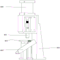
FIG. 12 is a schematic diagram of a stamping block structure of the stamping assembly of the present utility model.
Detailed Description
The principles and features of the present utility model are described below with reference to the drawings, the examples are illustrated for the purpose of illustrating the utility model and are not to be construed as limiting the scope of the utility model.
As shown in fig. 1 to 12, the embodiment provides an anderson plug 7 assembling machine, which comprises a frame 1, wherein the frame 1 comprises a machine table 101, a rotary processing platform 3 is arranged on the frame 1, a plug feeding mechanism 2 is arranged on one side of the frame 1, a pole piece preassembling mechanism 4 is arranged on the other side of the frame 1, a secondary pressing mechanism 5 is also arranged on one side of the rotary processing platform 3, a feeding detection mechanism 6 is arranged on one side of the rotary processing platform 3, and an embossing assembly is arranged on one side of the tail part of the feeding detection mechanism 6; the rotary processing platform 3 comprises a fixed disc 301, the fixed disc 301 is circular, a gear transmission case 308 is arranged on the lower side of the fixed disc 301 (the gear transmission case 308 is in the prior art and is not repeated herein), the gear transmission case 308 is fixedly arranged on the machine 101, a rotating shaft on the gear transmission case 308 is fixedly connected to the center of the fixed disc 301, a servo motor 307 is arranged on the lower side of the gear transmission case 308, a driving wheel 306 is sleeved on a rotating main shaft of the servo motor 307, a belt 305 is sleeved on the driving wheel 306, a transmission rod 303 penetrating through the gear transmission case 308 is arranged on the lower portion of the gear transmission case 308, a driven wheel 304 is arranged at one end of the transmission rod 303, the driven wheel 304 is in transmission connection with the driving wheel 306 through the belt 305, an induction wheel piece 309 is arranged at the other end of the transmission rod 303 on the lower portion of the gear transmission case 308, an inductor 310 is arranged on one side of the induction wheel piece 309, and 8 dies 302 are uniformly arranged on the fixed disc 301 along the circle center for fixing the anderson plug 7.
The plug feeding mechanism 2 comprises a vibration feeding component (the feeding component is in the prior art and is not repeated herein), a plug feeding pipe 205 is fixedly arranged at the upper end of the vibration feeding component, the plug feeding pipe 205 is fixedly arranged on the machine 101 through a supporting rod 208, one end of the plug feeding pipe 205 is arranged on the adjacent side of the rotary processing platform 3, a feeding cylinder group is arranged at the right upper end of the plug feeding pipe 205, the feeding cylinder group is fixedly arranged right above the plug feeding pipe 205 through a feeding cylinder mounting plate 206, the feeding cylinder mounting plate 206 is fixedly arranged on the machine 101, and the feeding cylinder group comprises a first feeding cylinder 201, a second feeding cylinder 202 and a third feeding cylinder; the first feeding cylinder 201 is fixedly arranged on one side of the feeding cylinder mounting plate 206, the second feeding cylinder 202 is vertically arranged on one side of the first feeding cylinder 201, the cylinder body of the second feeding cylinder 202 is fixedly connected with the piston rod of the first feeding cylinder 201, the bottom of the third feeding cylinder 203 is fixedly connected with the piston rod of the second feeding cylinder 202, the third feeding cylinder 203 is a clamping jaw cylinder, the anderson plug 7 on the plug feeding pipe 205 is moved into the die 302 on the fixed disc 301 through the feeding cylinder, a flattening mechanism is arranged on one side of the plug feeding mechanism 2 and comprises a flattening cylinder 313, the flattening cylinder 313 is fixedly arranged at one end of the flattening cylinder connecting block 312, one end of the flattening cylinder connecting block 312 is fixedly arranged on the upper portion of the flattening rod 311 through a fixing piece, the flattening cylinder 313 is fixedly arranged on the machine table 101 through a flattening rod 311, the flattening cylinder connecting block 314 is fixedly connected with one end of the piston rod of the flattening cylinder 313 through a fastening piece, and the flattening mechanism is arranged in order that the plug feeding mechanism 2 does not place the anderson plug 7 in a flattening position, and further processing is convenient.
The pole piece preassembling mechanism 4 comprises a positive pole piece feeding component and a negative pole piece feeding component, a pole piece preassembling component is arranged between the positive pole piece feeding component and the negative pole piece feeding component, the positive pole piece feeding component and the negative pole piece feeding component are respectively provided with a pole piece feeding pipe 413 for conveying positive and negative pole pieces, vibration exciter 404 is arranged on the lower side of the pole piece feeding pipe 413, the pole piece feeding pipes 413 are connected to two sides of the pole piece preassembling component, the pole piece preassembling component comprises a preassembling component base 411, a preassembling component fixing block 406 is arranged on the preassembling component base 411, a sliding rail 409 is arranged on one side of the preassembling component fixing block 406, one side of the preassembling component fixing block 406 is provided with a preassembling component mounting block 407, the preassembling component mounting block 407 is in sliding connection with the preassembling component fixing block 406 through a sliding block 408, one side of the preassembling component mounting block 407 is provided with a preassembling cylinder 410, a piston rod of the preassembling component mounting plate 407 is fixedly connected with one side of the preassembling component mounting plate, one side of the preassembling component mounting plate 402 is correspondingly provided with a material containing seat 402, a groove is formed in front of the left side and the preassembling component mounting block and the right side of the preassembling component mounting block is provided with a groove, the vibration exciter 402 is not provided with a groove, and the vibration exciter 402 is arranged on the two sides of the positive and the negative side and the pole plate mounting plate 402 are not correspondingly provided with a groove 401, and the vibration exciter mounting plate 402 is not provided with a positive and a groove, and the vibration exciter mounting plate is not provided with a vibration exciter mounting plate 402, and the vibration exciter mounting plate is not provided with a vibration exciter is provided with a vibration exciter on the two side of the side and a vibration exciter plate 402.
The secondary material pressing mechanism comprises a secondary material pressing mechanism base 501 arranged on the machine table 101, a material pressing cylinder 502 is fixedly arranged on the secondary material pressing mechanism base, two material pressing rods 503 are arranged on piston rods of the material pressing cylinder 502, a guide seat 504 is arranged on one side of the material pressing cylinder 502, a through hole for the material pressing rods 503 to slide is formed in the guide seat 504, and the through hole is arranged to enable the secondary material pressing mechanism 5 to accurately press a pole piece in working.
The feeding detection mechanism 6 comprises a feeding cylinder assembly, the feeding cylinder assembly comprises a feeding base 601 fixedly arranged on the machine 101, a first feeding cylinder 602 is arranged on one side of the upper portion of the feeding base 601, the first feeding cylinder 602 is a deflection cylinder, a second feeding cylinder 603 is fixedly arranged on a rotary platform of the deflection cylinder, the second feeding cylinder 603 is a sliding table cylinder, a feeding seat 604 is fixedly arranged on one side of the second feeding cylinder 603, two feeding rods 605 are fixedly arranged on the feeding seat 604, a feeding assembly is arranged on one side of the feeding cylinder assembly and fixedly arranged on the machine 101 through a plurality of groups of feeding assembly supporting plates 613, the feeding assembly comprises a conveyor belt 612, a first pushing cylinder 510 is arranged on the front portion of the conveyor belt 612, a second pushing cylinder 614 is arranged on one side of the middle portion of the conveyor belt 512 and is a detection member 616 (the detection member is of the prior art, and is not repeated), a first inclined surface 614 is arranged on one side of the conveyor belt 612 opposite to the second pushing cylinder 614, and a third inclined surface 614 is arranged on the other side of the conveyor belt 612.
The embossing assembly comprises an embossing cylinder 520, the embossing cylinder 520 is fixedly arranged on the machine 101 through an embossing cylinder mounting plate 524, the embossing assembly comprises a conveying seat 622 fixedly arranged on the machine 101, a chute for sliding an anderson plug 7 is formed in the conveying seat 622, the conveying seat 622 is correspondingly arranged with a third pushing cylinder, the anderson plug 7 can be directly pushed onto the conveying seat 622 by the third pushing cylinder 614, an embossing cylinder 620 is arranged above the middle part of the conveying seat 622, an embossing block 621 is arranged on a piston rod of the embossing cylinder 620, two protrusions 640 are arranged at the lower end of the embossing block 621, a second inclined plane 623 is arranged on one side of the conveying seat 622, and a processed plug slides into a finished frame or other devices through the second inclined plane 623.
Working principle: the device is electrified, the Andersen plug 7 and the positive and negative pole pieces are respectively put into the feeding mechanism, the feeding mechanism starts to work, the plug feeding mechanism 2 conveys the Andersen plug 7 to the plug feeding pipe 205 through vibration, a baffle is arranged at one end of the plug feeding pipe 205 to prevent the plug 7 from being extruded out excessively, and meanwhile, a positioning function is also achieved, then the feeding cylinder group acts, the piston rod of the second feeding cylinder 202 stretches out, after the third feeding cylinder 203 is sent to a designated position, the third feeding cylinder 203 controls the clamping jaw 204 to clamp the plug, the piston rod of the second feeding cylinder 202 retracts, the piston rod of the first feeding cylinder 201 stretches out, the second feeding cylinder 202 and the third feeding cylinder 203 are sent to the upper part of the die 302 of the fixed disc 301 forward, at the moment, the piston rod of the second feeding cylinder 202 stretches out, the third feeding cylinder 203 descends down, the plug 7 is placed in the die 302, the third feeding cylinder 203 controls the clamping jaw 204 to loosen, the second feeding cylinder 202 retracts, then the piston rod of the third feeding cylinder 203 retracts, the feeding cylinder group returns to the waiting position, the feeding cylinder group repeatedly circulates the plug feeding action, after the plug feeding is completed, the servo motor 307 acts to control the gear box 308 to drive the fixed disc 301 to rotate a certain angle, the rotating angle of the fixed disc 301 is controlled by the sensor 310 on one side of the gear box 308, when the die 302 on the fixed disc 301 rotates to the flattening mechanism, the fixed disc 301 stops rotating, the flattening mechanism acts, the piston rod of the flattening cylinder 313 extends out to drive the flattening block 314 to press the plug into place, the fixed disc 301 rotates again, the positive and negative pole pieces are stopped when rotating to the pole piece pre-rotating mechanism 4, the positive and negative pole pieces are conveyed to the material accommodating seat 402 of the pole piece pre-rotating mechanism 4, the sensor 401 on the material accommodating seat 402 obtains signals, the vibration exciter 404 is controlled to stop working, if the vibration exciter 404 works, more pole pieces are sent into the material containing seat 402, the operation of the following preassembled pole pieces can be influenced, after the positive pole pieces and the negative pole pieces are sent onto the material containing seat 402, the preassembling cylinder 410 acts to drive the two preassembled rods 405 on the preassembled component fixing block 407 to move towards the plug 7 along the positive pole pieces and the negative pole pieces, the positive pole pieces and the negative pole pieces are propped into the plug 7, the preassembling cylinder 410 acts to retract the piston rod, the servo motor 307 drives the fixing disc 301 to rotate, the operation is stopped when the die 302 rotates to the secondary material pressing mechanism, the material pressing cylinder 502 acts to extend the piston rod to move towards the plug to press the preassembled pole pieces in place, then the operation piston rod of the material pressing cylinder retracts to move towards the material pressing cylinder, the servo motor 307 acts to drive the fixing disc 301 to rotate, the operation is stopped when the die 302 rotates to the material taking cylinder component, the material taking cylinder assembly moves, the piston rod of the second material taking cylinder 603 is upwards in a material taking cylinder group waiting position state, after the die 302 is in place, the deflection platform of the first material taking cylinder 602 drives the second material taking cylinder 603 to rotate 90 degrees towards the direction of the rotary processing platform 3, after the rotation is finished, the piston rod of the second material taking cylinder 603 moves to extend to drive the material taking rod 605 of the material taking seat 604 to move towards the direction of the plug together, the material taking rod 605 is inserted into the plug, the first material taking cylinder 602 moves back to the waiting position, the plug is inserted onto the material taking rod 605, the first material taking cylinder 602 rotates towards the direction of the material feeding assembly, at the moment, one end of the material taking rod 605 is arranged on the object stage of the material feeding assembly, the piston rod of the second material taking cylinder 603 retracts to drive the material taking rod 605 to move, a bulge is arranged in the position corresponding to the middle of the material taking rod 605, the plug 7 is left on the object stage when the material taking rod 605 retracts towards the direction, the first pushing air 610 cylinder acts to push the plug 7 forward, the plug 7 at the forefront of the object stage is pushed onto the conveyor belt 612 through extrusion, when the plug 7 of the conveyor belt 612 moves past the detecting piece 616, the detecting piece 616 detects that the pole piece is not in place, the unqualified product which is not in place is pushed out of the conveyor belt 612 by the second pushing air cylinder 614, falls into the unqualified product frame through the first inclined plane 615, the qualified product continues to move, the third pushing air cylinder 617 pushes the plug into the conveying groove on the conveying seat 622 after the qualified plug 7 moves to the bottom, the plug 7 is continuously pushed to move by the third pushing air cylinder 617, and when the plug 7 moves to the lower part of the embossing air 620 cylinder, the embossing air cylinder 620 acts to drive the embossing block 621 to move downwards to press out the stamp on the plug 7, and then the qualified product frame 623 falls into the finished product frame through the second inclined plane.
Finally, it should be noted that: the foregoing description is only a preferred embodiment of the present utility model, and the present utility model is not limited thereto, but it is to be understood that modifications and equivalents of some of the technical features described in the foregoing embodiments may be made by those skilled in the art, although the present utility model has been described in detail with reference to the foregoing embodiments. Any modification, equivalent replacement, improvement, etc. made within the spirit and principle of the present utility model should be included in the protection scope of the present utility model.
Claims (10)
1. An anderson plug kludge, its characterized in that: the device comprises a frame, wherein the frame comprises a machine table, a rotary processing platform is arranged on the frame, a plug feeding mechanism is arranged on one side of the frame, a flattening mechanism is arranged on one side of the plug feeding mechanism, a pole piece preassembling mechanism is arranged on the other side of the frame, a secondary pressing mechanism is further arranged on one side of the rotary processing platform, a feeding detection mechanism is arranged on one side of the rotary processing platform, and an embossing assembly is arranged on one side of the tail of the feeding detection mechanism;
the rotary processing platform comprises a fixed disc, a gear box is arranged on the lower side of the fixed disc, a rotating shaft on the gear box is fixedly connected to the center of the fixed disc, and a plurality of dies are further arranged on the fixed disc;
the plug feeding mechanism comprises a vibration feeding assembly, a plug feeding pipe is fixedly arranged at the upper end of the vibration feeding assembly, one end of the plug feeding pipe is arranged on the adjacent side of the rotary processing platform, a feeding cylinder group is arranged at the upper end of the plug feeding pipe, and the feeding cylinder group comprises a first feeding cylinder, a second feeding cylinder and a third feeding cylinder;
the flattening mechanism comprises a flattening cylinder, and one end of a piston rod of the flattening cylinder is fixedly connected with a flattening block;
the pole piece preassembling mechanism comprises a positive pole piece feeding assembly and a negative pole piece feeding assembly, and a pole piece preassembling assembly is arranged between the positive pole piece feeding assembly and the negative pole piece feeding assembly;
the secondary material pressing mechanism comprises a material pressing cylinder;
the feeding detection mechanism comprises a material taking cylinder assembly, one side of the material taking cylinder assembly is provided with a feeding assembly, and one side of the feeding assembly is provided with a CCD detection piece;
the embossing assembly includes an embossing cylinder.
2. An anderson plug assembly machine according to claim 1, wherein: the automatic transmission device is characterized in that a servo motor is arranged on the lower side of the gear transmission box, a driving wheel is sleeved on a rotating main shaft of the servo motor, a belt is sleeved on the driving wheel, a transmission rod penetrating through the gear transmission box is arranged on the lower portion of the gear transmission box, a driven wheel is arranged at one end of the transmission rod, and the driven wheel is in transmission connection with the driving wheel through the belt.
3. An anderson plug assembly machine according to claim 2, characterized in that: the other end of the transmission rod at the lower part of the gear transmission box is provided with an induction wheel piece, and one side of the induction wheel piece is provided with an inductor.
4. An anderson plug assembly machine according to claim 1, wherein: the feeding cylinder group is fixedly arranged right above the plug feeding pipe through a feeding cylinder mounting plate, and the feeding cylinder mounting plate is fixedly arranged on the machine table.
5. The anderson plug assembly machine of claim 4, wherein: the first feeding cylinder is fixedly arranged on one side of the feeding cylinder mounting plate, the second feeding cylinder is vertically arranged on one side of the first feeding cylinder, the cylinder body of the second feeding cylinder is fixedly connected with the piston rod of the first feeding cylinder, the bottom of the third feeding cylinder is fixedly connected with the piston rod of the second feeding cylinder, and the third feeding cylinder is a clamping jaw cylinder.
6. An anderson plug assembly machine according to claim 1, wherein: the positive plate feeding assembly and the negative plate feeding assembly are respectively provided with a plate feeding pipe for conveying the positive plate and the negative plate, vibration exciters are arranged on the lower sides of the plate feeding pipes, and the plate feeding pipes are connected to the two sides of the plate preassembling assembly.
7. The anderson plug assembly machine of claim 6, wherein: the pole piece pre-assembly comprises a pre-assembly base, a pre-assembly fixing block is arranged on the pre-assembly base, a sliding rail is arranged on one side of the pre-assembly fixing block, a pre-assembly installation block is arranged on one side of the pre-assembly fixing block, the pre-assembly installation block is in sliding connection with the pre-assembly fixing block through a sliding block and the sliding rail, two pre-assembly rods are fixedly arranged on the pre-assembly installation block, a pre-assembly cylinder is arranged on one side of the pre-assembly installation block, a piston rod of the pre-assembly cylinder is fixedly arranged on one side of the pre-assembly fixing block and fixedly connected with one side of the pre-assembly installation plate, a material containing seat is correspondingly arranged on one side of the pre-assembly rod, grooves are formed in the material containing seat in the front, the back, the left and the right directions, and an inductor is correspondingly arranged above the material containing seat.
8. An anderson plug assembly machine according to claim 1, wherein: the secondary pressing mechanism further comprises a secondary pressing mechanism base arranged on the machine table, the secondary pressing mechanism base is fixedly provided with a pressing cylinder, a piston rod of the pressing cylinder is provided with two pressing rods, one side of the pressing cylinder is provided with a guide seat, and the guide seat is provided with a through hole for the pressing rods to slide.
9. An anderson plug assembly machine according to claim 1, wherein: the material taking cylinder assembly comprises a material taking base fixedly arranged on a machine table, a first material taking cylinder is arranged on one side of the upper portion of the material taking base, a second material taking cylinder is fixedly arranged on a rotary platform of the deflection cylinder and is a sliding table cylinder, a material taking seat is fixedly arranged on one side of the second material taking cylinder, two material taking rods are fixedly arranged on the material taking seat, the material feeding assembly is fixedly arranged on the machine table through a plurality of groups of material feeding assembly supporting plates, the material feeding assembly comprises a conveyor belt, a first material pushing cylinder is arranged on the front portion of the conveyor belt, a second material pushing cylinder is arranged on one side of the middle portion of the conveyor belt, a detection part is arranged on the front portion of one side opposite to the second material pushing cylinder, a first inclined surface is arranged on one side opposite to the second material pushing cylinder, a third material pushing cylinder is arranged on one side of the bottom of the conveyor belt, and an inductor is arranged on the upper side of the conveyor belt on the adjacent side of the third material pushing cylinder.
10. An anderson plug assembly machine according to claim 1, wherein: the embossing assembly comprises a conveying seat fixedly arranged on the machine table, the conveying seat is arranged corresponding to the third pushing cylinder, an embossing cylinder is arranged on the upper side of the conveying seat, an embossing block is arranged on a piston rod of the embossing cylinder, and a second inclined plane is arranged on one side of the conveying seat.
Priority Applications (1)
| Application Number | Priority Date | Filing Date | Title |
|---|---|---|---|
| CN202223043666.4U CN219094275U (en) | 2022-11-16 | 2022-11-16 | Andersen plug assembly machine |
Applications Claiming Priority (1)
| Application Number | Priority Date | Filing Date | Title |
|---|---|---|---|
| CN202223043666.4U CN219094275U (en) | 2022-11-16 | 2022-11-16 | Andersen plug assembly machine |
Publications (1)
| Publication Number | Publication Date |
|---|---|
| CN219094275U true CN219094275U (en) | 2023-05-30 |
Family
ID=86463404
Family Applications (1)
| Application Number | Title | Priority Date | Filing Date |
|---|---|---|---|
| CN202223043666.4U Active CN219094275U (en) | 2022-11-16 | 2022-11-16 | Andersen plug assembly machine |
Country Status (1)
| Country | Link |
|---|---|
| CN (1) | CN219094275U (en) |
Cited By (1)
| Publication number | Priority date | Publication date | Assignee | Title |
|---|---|---|---|---|
| CN116984167A (en) * | 2023-09-26 | 2023-11-03 | 四川富士电机有限公司 | Windscreen wiper support surface spraying equipment |
-
2022
- 2022-11-16 CN CN202223043666.4U patent/CN219094275U/en active Active
Cited By (2)
| Publication number | Priority date | Publication date | Assignee | Title |
|---|---|---|---|---|
| CN116984167A (en) * | 2023-09-26 | 2023-11-03 | 四川富士电机有限公司 | Windscreen wiper support surface spraying equipment |
| CN116984167B (en) * | 2023-09-26 | 2023-11-28 | 四川富士电机有限公司 | Windscreen wiper support surface spraying equipment |
Similar Documents
| Publication | Publication Date | Title |
|---|---|---|
| CN211027822U (en) | Automatic stamping equipment for sheet stamping | |
| CN211218799U (en) | Glass mold drilling device | |
| CN217044149U (en) | Continuous stamping die for metal stamping | |
| CN210588100U (en) | Tubular product throat device that punches for metalworking | |
| CN117013772B (en) | Processing device for stator and rotor punching sheet of motor | |
| CN118367226A (en) | Intelligent assembly machine for processing full-lug sodium ion battery | |
| CN215824105U (en) | Feeding and discharging device of punch press | |
| CN112886355B (en) | Full-automatic soldering tin assembly production line | |
| CN215699477U (en) | Automatic installation device for gear box fixed block component | |
| CN117790873A (en) | Turntable manipulator for electric core rubberizing | |
| CN205732426U (en) | A kind of lead set automatic roll equipment | |
| CN215358060U (en) | Pressing mechanism and automatic equipment | |
| CN110842562A (en) | Nickel sheet feeding device on lithium battery welding line | |
| CN112045079B (en) | Automatic processing equipment for clamping piece of multifunctional electric power instrument | |
| CN210059374U (en) | Round pipe extruding boss flanging equipment | |
| CN117816832B (en) | Profile stamping device, photovoltaic frame automatic production line and production method | |
| CN223145814U (en) | Automatic piece feeding device for stamping of photovoltaic support | |
| CN224168548U (en) | Impeller riveting device | |
| CN224101641U (en) | Sheet metal shell stamping integrated mold | |
| CN222831107U (en) | Automatic assembly mechanism for check ring for hole | |
| CN211017694U (en) | Photovoltaic connector installation equipment | |
| CN117282852B (en) | Device is used in automatic processing of photovoltaic support | |
| CN221289186U (en) | Efficient assembly device for copper terminals | |
| CN220964021U (en) | Pitch-changing end inserting mechanism | |
| CN113783377B (en) | A magnetic pole core flattening device for electric motor manufacturing capable of fast loading |
Legal Events
| Date | Code | Title | Description |
|---|---|---|---|
| GR01 | Patent grant | ||
| GR01 | Patent grant |