CN214371019U - Solar panel support for power equipment - Google Patents
Solar panel support for power equipment Download PDFInfo
- Publication number
- CN214371019U CN214371019U CN202120529847.4U CN202120529847U CN214371019U CN 214371019 U CN214371019 U CN 214371019U CN 202120529847 U CN202120529847 U CN 202120529847U CN 214371019 U CN214371019 U CN 214371019U
- Authority
- CN
- China
- Prior art keywords
- supporting
- rods
- assembly
- driving
- adjusting
- Prior art date
- Legal status (The legal status is an assumption and is not a legal conclusion. Google has not performed a legal analysis and makes no representation as to the accuracy of the status listed.)
- Expired - Fee Related
Links
Images


Classifications
-
- Y—GENERAL TAGGING OF NEW TECHNOLOGICAL DEVELOPMENTS; GENERAL TAGGING OF CROSS-SECTIONAL TECHNOLOGIES SPANNING OVER SEVERAL SECTIONS OF THE IPC; TECHNICAL SUBJECTS COVERED BY FORMER USPC CROSS-REFERENCE ART COLLECTIONS [XRACs] AND DIGESTS
- Y02—TECHNOLOGIES OR APPLICATIONS FOR MITIGATION OR ADAPTATION AGAINST CLIMATE CHANGE
- Y02E—REDUCTION OF GREENHOUSE GAS [GHG] EMISSIONS, RELATED TO ENERGY GENERATION, TRANSMISSION OR DISTRIBUTION
- Y02E10/00—Energy generation through renewable energy sources
- Y02E10/40—Solar thermal energy, e.g. solar towers
- Y02E10/47—Mountings or tracking
-
- Y—GENERAL TAGGING OF NEW TECHNOLOGICAL DEVELOPMENTS; GENERAL TAGGING OF CROSS-SECTIONAL TECHNOLOGIES SPANNING OVER SEVERAL SECTIONS OF THE IPC; TECHNICAL SUBJECTS COVERED BY FORMER USPC CROSS-REFERENCE ART COLLECTIONS [XRACs] AND DIGESTS
- Y02—TECHNOLOGIES OR APPLICATIONS FOR MITIGATION OR ADAPTATION AGAINST CLIMATE CHANGE
- Y02E—REDUCTION OF GREENHOUSE GAS [GHG] EMISSIONS, RELATED TO ENERGY GENERATION, TRANSMISSION OR DISTRIBUTION
- Y02E10/00—Energy generation through renewable energy sources
- Y02E10/50—Photovoltaic [PV] energy
Abstract
The utility model provides a solar panel bracket for power equipment, which comprises an electroplate body, a supporting component and an adjusting mechanism, wherein one side of the electroplate body is connected with the supporting component through a first connecting piece, and the other side of the electroplate body is arranged on the supporting component through the adjusting mechanism; the adjusting mechanism comprises a first adjusting assembly, a second adjusting assembly and a driving assembly which are arranged on the supporting assembly, and the first adjusting assembly and the second adjusting assembly are respectively connected with the driving assembly; the first adjusting assembly comprises driving screw rods, a thread block and a control rod, and the two driving screw rods are arranged on the supporting assembly in parallel; the two thread blocks are respectively in threaded connection with the two driving screws; the control rod is provided with a control groove; the second adjusting component comprises a sliding block and supporting rods, and the other ends of the two supporting rods are connected with the electric plate body. The utility model provides the high convenience of adjusting supporting structure flexibility and use, the solar panel's of being convenient for inclination adjusts, is convenient for transfer solar panel to suitable inclination position.
Description
Technical Field
The utility model relates to a solar panel technical field specifically is a solar panel support for power equipment.
Background
A solar cell is also called a "solar chip" or a "photovoltaic cell", and is a photoelectric semiconductor sheet that directly generates electricity by using sunlight. The single solar cell cannot be directly used as a power supply. As a power supply, a plurality of single solar cells must be connected in series, in parallel and tightly packaged into an assembly. An assembly of a plurality of solar cells of a solar panel (also called a solar cell module) is a core part of a solar power generation system and is also the most important part of the solar power generation system.
The solar power generation mode has two modes, one is a light-heat-electricity conversion mode, and the other is a light-electricity direct conversion mode. (1) The light-heat-electricity conversion mode is to generate electricity by utilizing the heat energy generated by solar radiation, generally, a solar heat collector converts the absorbed heat energy into steam of a working medium and then drives a steam turbine to generate electricity. The former process is a light-to-heat conversion process; the latter process is a thermo-electric conversion process. (2) The photoelectric direct conversion mode is to directly convert solar radiation energy into electric energy by using the photoelectric effect, and a basic device for the photoelectric conversion is a solar cell. The solar cell is a device which directly converts solar energy into electric energy due to photovoltaic effect, and is a semiconductor photodiode. When a plurality of batteries are connected in series or in parallel, a solar battery matrix with larger output power can be formed.
In the use of the existing solar panel support, the flexibility of the adjusting support structure of the adjusting support is poor, so that the inclination angle of the solar panel is inconvenient to adjust, and the solar panel is difficult to adjust to a proper inclination angle position.
SUMMERY OF THE UTILITY MODEL
The to-be-solved technical problem of the utility model is to overcome current defect, provide a solar panel support for power equipment to solve among the above-mentioned technical background because the regulation supporting structure flexibility of adjusting the support is relatively poor with the use convenience, lead to solar panel's inclination to adjust inconveniently, be difficult to transfer solar panel to the shortcoming of suitable inclination position.
In order to achieve the above object, the utility model provides a following technical scheme: a solar panel support for power equipment comprises an electric panel body, a supporting component and an adjusting mechanism, wherein one side of the electric panel body is connected with the supporting component through a first connecting piece, and the other side of the electric panel body is arranged on the supporting component through the adjusting mechanism;
the adjusting mechanism comprises a first adjusting assembly, a second adjusting assembly and a driving assembly which are arranged on the supporting assembly, and the first adjusting assembly and the second adjusting assembly are respectively connected with the driving assembly; the first adjusting assembly comprises driving screw rods, thread blocks and a control rod, the two driving screw rods are arranged on the supporting assembly in parallel, and the thread blocks are sleeved on the driving screw rods; the two thread blocks are respectively in threaded connection with the two driving screws, and the two thread blocks are connected through the control rod; the control rod is provided with a control groove;
the second adjusting assembly comprises sliding blocks and supporting rods, and the two sliding blocks are arranged in the control grooves and are respectively connected with one ends of the two supporting rods; the other ends of the two support rods are connected with the electric plate body and are far away from the first connecting piece.
Preferably, the support assembly comprises cross rods and connecting rods, and the two cross rods are arranged in parallel and connected through the two connecting rods; the two connecting rods are parallel to each other, and the adjacent surfaces of the two connecting rods are provided with driving grooves.
Preferably, the two driving screws are respectively arranged in the two driving grooves; the thread block is arranged in the driving groove and matched with the driving groove.
Preferably, the first connecting piece comprises a fixed block, a first rotating shaft, a supporting column and a fixed column, the two fixed blocks are arranged on one of the cross rods, and the two fixed blocks are far away from each other; the first rotating shaft is arranged between the two fixed blocks, and two ends of the first rotating shaft are respectively connected with the fixed blocks; one end of the supporting column is arranged on the first rotating shaft, and the other end of the supporting column is movably connected with one end of the fixed column; the other end of the fixing column is connected with the electric plate body.
Preferably, one ends of the two support rods, which are far away from the sliding block, are connected with the electric plate body through a second connecting piece; the second connecting piece comprises a transmission rod and a third rotating shaft, and the third rotating shaft is arranged on the supporting rod and connected with the transmission rod; the other end of the transmission rod is connected with the electric plate body through the first connecting block.
Compared with the prior art, the utility model provides a solar panel support for power equipment possesses following beneficial effect:
the utility model discloses in rotate through driving screw and be convenient for drive the screw thread piece and carry out the steady removal on driving screw, and connect through the control lever between two screw thread pieces, and be connected through the bracing piece between control lever and the electroplax body, be convenient for change the inclination of short plate body, and the control flume has been seted up on the control lever, be equipped with two sliders in the control flume, two sliders are joint support pole's one end respectively, also can change the angle of electroplax body when moving the different position in the control flume through two sliders, the convenience of adjusting supporting structure flexibility and use has been improved, be convenient for solar panel's inclination adjustment, be convenient for transfer solar panel to suitable inclination position.
Drawings
The accompanying drawings are included to provide a further understanding of the invention, and are incorporated in and constitute a part of this specification, illustrate embodiments of the invention, and together with the description, do not constitute a limitation of the invention, in which:
fig. 1 is a schematic view of a simple structure of a solar panel bracket for power equipment according to the present invention;
FIG. 2 is an enlarged schematic view of the structure at A of the present invention;
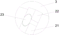
FIG. 3 is an enlarged schematic view of the structure at B of the present invention;
fig. 4 is an enlarged schematic structural diagram of the position C of the present invention.
In the figure: 1. a cross bar; 2. a connecting rod; 3. an electrode plate body; 4. a drive slot; 5. a drive motor; 6. a drive screw; 7. a control lever; 8. a control slot; 9. a support bar; 10. a first connection block; 11. a transmission rod; 12. a fixed block; 13. a first rotating shaft; 14. mounting blocks; 15. mounting holes; 16. a thread block; 17. a micro cylinder; 18. an output rod; 19. a slider; 20. a second connecting block; 21. a support pillar; 22. fixing a column; 23. a second rotating shaft; 24. and a third rotating shaft.
Detailed Description
In order to make the technical means, the creation features, the achievement purposes and the functions of the present invention easy to understand, the present invention will be further explained below with reference to the following embodiments and the accompanying drawings, but the following embodiments are only preferred embodiments of the present invention, and not all embodiments are included. Based on the embodiments in the implementation, other embodiments obtained by those skilled in the art without any creative work belong to the protection scope of the present invention.
Referring to fig. 1-4, a solar panel support for power equipment includes an electric plate body 3, a support assembly and an adjusting mechanism, wherein one side of the electric plate body 3 is connected to the support assembly through a first connecting member, and the other side is disposed on the support assembly through the adjusting mechanism.
The adjusting mechanism comprises a first adjusting assembly, a second adjusting assembly and a driving assembly which are arranged on the supporting assembly, and the first adjusting assembly and the second adjusting assembly are respectively connected with the driving assembly; the first adjusting assembly comprises driving screw rods 6, thread blocks 16 and a control rod 7, the two driving screw rods 6 are arranged on the supporting assembly in parallel, and the thread blocks 16 are sleeved on the driving screw rods 6; the two thread blocks 16 are respectively in threaded connection with the two driving screws, and the two thread blocks 16 are connected through the control rod 7; a control groove 8 is arranged on the control rod 7; be equipped with driving motor 5 in the drive slot 4, driving screw 6 is connected to driving motor 5's output, is convenient for drive driving screw 6 and rotates, and drives threaded connection's on driving screw 6 screw thread piece 16 and carry out steady removal on driving screw 6, is convenient for change the inclination of electroplax body 3 through control lever 7 and bracing piece 9.
The second adjusting assembly comprises a sliding block 19 and supporting rods 9, the two sliding blocks 19 are arranged in the control groove 8, the sliding blocks 19 can stably slide in the control groove 8, and are respectively movably connected with one ends of the two supporting rods 9 through second connecting blocks 20; two micro cylinders 17 are arranged in the control groove 8, the two micro cylinders 17 are far away from each other, and output rods 18 of the two micro cylinders 17 are respectively connected with two sliding blocks 19; the other ends of the two support rods 9 are connected with the electric plate body 3 and are far away from the first connecting piece.
The supporting assembly comprises cross rods 1 and connecting rods 2, wherein the two cross rods 1 are arranged in parallel and are connected through the two connecting rods 2; two connecting rods 2 are parallel to each other, and drive groove 4 has all been seted up on two connecting rods 2 on the adjacent face.
The two driving screws 6 are respectively arranged in the two driving grooves 4; the screw block 16 is arranged in the driving groove 4 and matched with the driving groove 4, and the screw block 16 can stably slide in the driving groove 4.
The first connecting piece comprises fixing blocks 12, a first rotating shaft 13, a supporting column 21 and fixing columns 22, the two fixing blocks 12 are arranged on one cross rod 1, and the two fixing blocks 12 are far away from each other; the first rotating shaft 13 is arranged between the two fixed blocks 12, and two ends of the first rotating shaft are respectively connected with the fixed blocks 12; one end of the supporting column 21 is arranged on the first rotating shaft 13, and the other end of the supporting column is connected with one end of the fixed column 22 through a second rotating shaft 23; the other end of the fixing column 22 is fixedly connected with the electric plate body 3.
One ends of the two support rods 9 far away from the slide block 19 are connected with the electric plate body 3 through second connecting pieces; the second connecting piece comprises a transmission rod 11 and a third rotating shaft 24, and the third rotating shaft 24 is arranged on the supporting rod 9 and connected with the transmission rod 11; the other end of the transmission rod 11 is connected with the electric plate body 3 through a first connecting block 10, so that the support rod 9 can rotate around the connection part with the electric plate body 3.
Two ends of the two connecting rods 2 respectively suggest that the mounting blocks 14 are arranged, mounting holes 15 are formed in the mounting blocks 14, and the device can be conveniently mounted through the mounting holes 15 formed in the mounting blocks 14.
The utility model discloses a theory of operation and use flow: firstly, the installation of the device is facilitated by the installation hole 15 formed on the installation block 14, the driving screw 6 is driven to rotate by the driving motor 5, the thread block 16 in threaded connection with the driving screw 6 is driven to stably move in the driving groove 4, so as to drive the control rod 7 arranged between the two thread blocks 16 to move, the control rod 7 is connected with the electric plate body 3 through the support rod 9 and the second connecting piece, so as to facilitate the change of the inclination angle of the electric plate body 3, the control groove 8 is formed on the control rod 7, the micro cylinder 17 is arranged in the control groove 8, the output rod 18 on the micro cylinder 17 is connected with the slide block 19, the slide block 19 is connected with the support rod 9, the two slide blocks 19 are driven to move through the micro cylinder 17, so as to facilitate the change of the positions of the two slide blocks 19, thereby changing the positions of the two slide blocks 19 to the electric plate body 3 respectively, and further changing the inclination angle of the electric plate body 3, the convenience of adjusting the flexibility of the support structure and using is improved, the inclination angle of the solar panel is adjusted conveniently, and the solar panel is adjusted to a proper inclination angle position conveniently.
The foregoing shows and describes the general principles, essential features, and advantages of the invention. It should be understood by those skilled in the art that the present invention is not limited by the above embodiments, and the description in the above embodiments and the description is only preferred examples of the present invention, and is not intended to limit the present invention, and that the present invention can have various changes and modifications without departing from the spirit and scope of the present invention, and these changes and modifications all fall into the scope of the claimed invention. The scope of the invention is defined by the appended claims and equivalents thereof.
Claims (5)
1. A solar panel support for power equipment is characterized by comprising an electric plate body (3), a supporting component and an adjusting mechanism, wherein one side of the electric plate body (3) is connected with the supporting component through a first connecting piece, and the other side of the electric plate body is arranged on the supporting component through the adjusting mechanism;
the adjusting mechanism comprises a first adjusting assembly, a second adjusting assembly and a driving assembly which are arranged on the supporting assembly, and the first adjusting assembly and the second adjusting assembly are respectively connected with the driving assembly; the first adjusting assembly comprises driving screw rods (6), thread blocks (16) and a control rod (7), the two driving screw rods (6) are arranged on the supporting assembly in parallel, and the thread blocks (16) are sleeved on the driving screw rods (6); the two thread blocks (16) are respectively in threaded connection with the two driving screws, and the two thread blocks (16) are connected through the control rod (7); a control groove (8) is formed in the control rod (7);
the second adjusting assembly comprises sliding blocks (19) and supporting rods (9), and the two sliding blocks (19) are arranged in the control groove (8) and are respectively connected with one ends of the two supporting rods (9); the other ends of the two support rods (9) are connected with the electric plate body (3) and are far away from the first connecting piece.
2. A solar panel support for electrical equipment according to claim 1, wherein: the supporting assembly comprises cross rods (1) and connecting rods (2), the two cross rods (1) are arranged in parallel and are connected through the two connecting rods (2); two connecting rods (2) are parallel to each other, and two drive grooves (4) are formed in the adjacent surfaces of the two connecting rods (2).
3. A solar panel support for electrical equipment according to claim 2, wherein: the two driving screw rods (6) are respectively arranged in the two driving grooves (4); the thread block (16) is arranged in the driving groove (4) and matched with the driving groove (4).
4. A solar panel support for electrical equipment according to claim 2, wherein: the first connecting piece comprises fixing blocks (12), a first rotating shaft (13), a supporting column (21) and fixing columns (22), the two fixing blocks (12) are arranged on one cross rod (1), and the two fixing blocks (12) are far away from each other; the first rotating shaft (13) is arranged between the two fixed blocks (12), and two ends of the first rotating shaft are respectively connected with the fixed blocks (12); one end of the supporting column (21) is arranged on the first rotating shaft (13), and the other end of the supporting column is movably connected with one end of the fixing column (22); the other end of the fixed column (22) is connected with the electric plate body (3).
5. A solar panel support for electrical equipment according to claim 1, wherein: one ends of the two support rods (9) far away from the sliding block (19) are connected with the electric plate body (3) through second connecting pieces; the second connecting piece comprises a transmission rod (11) and a third rotating shaft (24), and the third rotating shaft (24) is arranged on the supporting rod (9) and connected with the transmission rod (11); the other end of the transmission rod (11) is connected with the electric plate body (3) through a first connecting block (10).
Priority Applications (1)
| Application Number | Priority Date | Filing Date | Title |
|---|---|---|---|
| CN202120529847.4U CN214371019U (en) | 2021-03-12 | 2021-03-12 | Solar panel support for power equipment |
Applications Claiming Priority (1)
| Application Number | Priority Date | Filing Date | Title |
|---|---|---|---|
| CN202120529847.4U CN214371019U (en) | 2021-03-12 | 2021-03-12 | Solar panel support for power equipment |
Publications (1)
| Publication Number | Publication Date |
|---|---|
| CN214371019U true CN214371019U (en) | 2021-10-08 |
Family
ID=77971155
Family Applications (1)
| Application Number | Title | Priority Date | Filing Date |
|---|---|---|---|
| CN202120529847.4U Expired - Fee Related CN214371019U (en) | 2021-03-12 | 2021-03-12 | Solar panel support for power equipment |
Country Status (1)
| Country | Link |
|---|---|
| CN (1) | CN214371019U (en) |
-
2021
- 2021-03-12 CN CN202120529847.4U patent/CN214371019U/en not_active Expired - Fee Related
Similar Documents
| Publication | Publication Date | Title |
|---|---|---|
| CN217849277U (en) | Spliced solar photovoltaic cell module | |
| CN210867581U (en) | But self-adjusting angle's single crystalline silicon solar photovoltaic support for board | |
| CN114826109A (en) | Solar photovoltaic power generation device suitable for roof installation is adjusted | |
| CN204494861U (en) | A kind of bimirror formula solar boiler | |
| CN209913744U (en) | Adjustable combined type independent photovoltaic power generation system | |
| CN214371019U (en) | Solar panel support for power equipment | |
| CN217522765U (en) | High adaptability photovoltaic power generation station photovoltaic board support frame | |
| CN214205415U (en) | Solar photovoltaic module with conveniently-adjusted inclination angle | |
| CN214480420U (en) | Oblique single-shaft linkage tracking type photovoltaic power generation device | |
| CN214014171U (en) | Solar cell panel installing support | |
| CN212413100U (en) | Position adjusting device for photovoltaic power generation | |
| CN214014155U (en) | Adjustable device of receiving light energy of solar PV modules | |
| CN210273921U (en) | Adjustable solar panel's outer wall connecting mechanism | |
| CN217469857U (en) | Sun-tracking solar module | |
| CN218217273U (en) | Double-sided light-receiving solar cell | |
| CN219960428U (en) | Adjustable wind-solar complementary power generation device | |
| CN104729114A (en) | Double-mirror type solar energy boiler | |
| CN219893229U (en) | Adjustable photovoltaic power generation device | |
| CN213243853U (en) | Assembled solar photovoltaic power station | |
| CN213661539U (en) | Device capable of adjusting angle of solar panel | |
| CN216772266U (en) | Solar cell panel capable of automatically tracking sun | |
| CN219697603U (en) | Monocrystalline silicon assembly with good heat dissipation performance | |
| CN215581016U (en) | Photovoltaic support based on photovoltaic power generation uses | |
| CN220678892U (en) | Photovoltaic module dust collector | |
| CN210518186U (en) | Solar panel capable of adjusting light receiving angle |
Legal Events
| Date | Code | Title | Description |
|---|---|---|---|
| GR01 | Patent grant | ||
| GR01 | Patent grant | ||
| CF01 | Termination of patent right due to non-payment of annual fee | ||
| CF01 | Termination of patent right due to non-payment of annual fee |
Granted publication date: 20211008 |