CN214287105U - Belt cleaning device is used in production of large-traffic filter core - Google Patents
Belt cleaning device is used in production of large-traffic filter core Download PDFInfo
- Publication number
- CN214287105U CN214287105U CN202022257679.6U CN202022257679U CN214287105U CN 214287105 U CN214287105 U CN 214287105U CN 202022257679 U CN202022257679 U CN 202022257679U CN 214287105 U CN214287105 U CN 214287105U
- Authority
- CN
- China
- Prior art keywords
- fixedly connected
- wall
- pipe
- box body
- cleaning device
- Prior art date
- Legal status (The legal status is an assumption and is not a legal conclusion. Google has not performed a legal analysis and makes no representation as to the accuracy of the status listed.)
- Active
Links
Images


Abstract
The utility model relates to a filter core production technical field just discloses a belt cleaning device is used in large-traffic filter core production, the power distribution box comprises a box body, the equal fixedly connected with bracing piece in four corners department of box lower surface, the fixed intercommunication of lateral wall on box right side has the blow off pipe, the outer wall fixedly connected with fixed plate on box right side, the lateral wall fixedly connected with pump machine of fixed plate upside, the fixed intercommunication of water inlet of pump machine has the drinking-water pipe, the fixed intercommunication of delivery port of pump machine has the aqueduct, the fixed intercommunication in upper end of aqueduct has U type pipe, U type pipe is located the box, the fixed intercommunication of pipe wall of U type pipe has a plurality of shower heads. The utility model discloses a set up multiple washing structure, the effectual cleaning efficiency that has improved, it is long when the effectual filter core that has reduced is dried, improved the production efficiency of filter core.
Description
Technical Field
The utility model relates to a filter core production technical field especially relates to a belt cleaning device is used in large-traffic filter core production.
Background
The large-flow filter element is a filter element for large-flow sewage treatment, after the filter element is produced and processed, a plurality of processing residues can be remained on the surface of the filter element, and the residues can influence the normal use of the filter element, so that the filter element needs to be cleaned by a cleaning device.
Through retrieval, a filter element washing and cleaning device is provided in the patent with the application patent number of CN207076215U, and the device comprises a base and a cup body, wherein a water inlet is arranged on the side edge of the base, a bottom groove is arranged at the bottom of the base, a side wall is arranged on the periphery of the bottom groove, and the water inlet is communicated with the bottom groove; the cup body is movably connected with the base through the side wall; one end of the cup body is open, the other end of the cup body is provided with an upper buckling groove, a water outlet channel is arranged in the upper buckling groove, and the water outlet channel extends outwards to form a water outlet.
Through the retrieval, proposed a filter core purger in the patent that application patent number is CN205903700U, including the casing, set up the washing subassembly in the casing, the first one of casing is equipped with the overflow mouth, and the casing lower half is equipped with the drain, wash the subassembly including by being responsible for and two Y venturi tubes that divide the pipe to constitute, set up the branch pipe on each branch pipe, be equipped with a plurality of through-holes on the branch pipe.
The above patents suffer from the following disadvantages:
firstly, when the cleaning device is used, the filter element is cleaned by spraying, and the cleaning mode is single, so that the cleaning efficiency is low;
second, and the clearance back, can remain a large amount of moisture on the filter core, need carry out long-time stoving, reduced the production efficiency of filter core.
SUMMERY OF THE UTILITY MODEL
The utility model aims at solving the problem that the cleaning efficiency of the cleaning device in the prior art is lower and the residual moisture is lower after the filter element is cleaned, and providing a cleaning device for producing large-flow filter elements.
In order to achieve the above purpose, the utility model adopts the following technical scheme:
a cleaning device for producing a large-flow filter element comprises a box body, wherein supporting rods are fixedly connected at four corners of the lower surface of the box body, a blow-off pipe is fixedly communicated with the side wall on the right side of the box body, a fixed plate is fixedly connected with the outer wall on the right side of the box body, a pump machine is fixedly connected with the side wall on the upper side of the fixed plate, a water pumping pipe is fixedly communicated with a water inlet of the pump machine, a water guide pipe is fixedly communicated with a water outlet of the pump machine, a U-shaped pipe is fixedly communicated with the upper end of the water guide pipe and is positioned in the box body, a plurality of spray heads are fixedly communicated with the pipe wall of the U-shaped pipe and are arranged in a downward inclination manner, a driving motor is fixedly connected with the outer wall on the left side of the box body, a rotating shaft is fixedly connected with an output shaft of the driving motor, a fixed hole is formed in the side wall on the left side of the box body, and penetrates through the fixed hole, the right-hand member fixedly connected with carousel of pivot, four even fixedly connected with threaded rods of lateral wall on carousel right side, four the equal thread bush of pole wall of threaded rod is equipped with an internal thread section of thick bamboo, the left end fixedly connected with clamp plate of an internal thread section of thick bamboo, the jack has been seted up to the left lateral wall of clamp plate, the clamp plate movable sleeve is located outside the threaded rod.
Preferably, a cover plate is arranged above the box body, and a limit frame plate is fixedly connected to the side wall of the lower side of the cover plate.
Preferably, the rotating shaft is fixedly sleeved with a bearing sleeve, and the left end of the bearing sleeve is located in the fixing hole.
Preferably, the outer wall of the internal thread cylinder is symmetrically and fixedly connected with two push rods.
Preferably, the lateral wall fixedly connected with U type pull rod of apron upside, the fixed cover of horizontal pole wall of U type pull rod is equipped with the sponge cover.
Preferably, the hole wall of the fixing hole is rotatably connected with the rotating shaft through a ball bearing.
Compared with the prior art, the utility model provides a belt cleaning device is used in large-traffic filter core production possesses following beneficial effect:
1. the cleaning device for producing the large-flow filter element is characterized by comprising a box body, a supporting rod, a blow-off pipe, a fixing plate, a pump, a water pumping pipe, a water guide pipe, a U-shaped pipe, a spray head, a driving motor, a rotating shaft, a fixing hole, a rotary disc, a threaded rod, an internal thread cylinder, a pressing plate and a jack, wherein the filter element is sleeved outside the threaded rod, the internal thread cylinder is rotated, the internal thread cylinder is matched with the threaded rod through threads, the internal thread cylinder moves leftwards, the pressing plate is driven by the internal thread cylinder to move leftwards, the pressing plate limits and fixes the filter element, so that the filter element is fixed on the threaded rod, the pump is controlled to work, the pump pumps water through the water pumping pipe, the pump conveys water into the U-shaped pipe through the water guide pipe, water in the U-shaped pipe is sprayed out through the plurality of spray heads, the filter element is cleaned, the driving motor drives the rotating shaft to rotate, the pivot drives the carousel and rotates, and the carousel drives the threaded rod rotatory to making the filter core rotatory, making the filter core evenly wash, the water that sprays falls into the box, the filter core that can the pairing rotation stirs the washing, this device is through setting up multiple washing structure, the effectual cleaning efficiency that has improved.
2. This belt cleaning device is used in large-traffic filter core production, through the driving motor, pivot, fixed orifices, carousel, threaded rod, an internal thread section of thick bamboo and the clamp plate that sets up, after the filter core washs the completion, through the water discharge of drain pipe in with the box, driving motor drives the filter core rotatory to throw away the water on the filter core, reduce remaining moisture on the filter core, it is long when effectual having reduced the filter core stoving, improved the production efficiency of filter core.
The part that does not relate to in the device all is the same with prior art or can adopt prior art to realize, the utility model discloses a set up multiple washing structure, the effectual cleaning efficiency that has improved, when the effectual filter core that has reduced is dried, improved the production efficiency of filter core.
Drawings
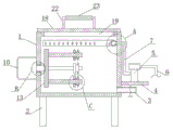
Fig. 1 is a schematic structural view of a cleaning device for producing a large-flow filter element according to the present invention;
FIG. 2 is a schematic structural view of portion A of FIG. 1;
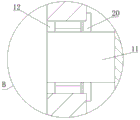
FIG. 3 is a schematic structural diagram of portion B of FIG. 1;
fig. 4 is a schematic structural view of a portion C in fig. 1.
In the figure: the device comprises a box body 1, a supporting rod 2, a sewage discharge pipe 3, a fixing plate 4, a pump 5, a water pumping pipe 6, a water guide pipe 7, a U-shaped pipe 8, a spray header 9, a driving motor 10, a rotating shaft 11, a fixing hole 12, a rotating disc 13, a threaded rod 14, an internal thread cylinder 15, a pressing plate 16, a jack 17, a cover plate 18, a limiting frame plate 19, a bearing sleeve 20, a push rod 21, a U-shaped pull rod 22 and a sponge sleeve 23.
Detailed Description
The technical solutions in the embodiments of the present invention will be described clearly and completely with reference to the accompanying drawings in the embodiments of the present invention, and it is obvious that the described embodiments are only some embodiments of the present invention, not all embodiments.
In the description of the present invention, it is to be understood that the terms "upper", "lower", "front", "rear", "left", "right", "top", "bottom", "inner", "outer", and the like indicate orientations or positional relationships based on the orientations or positional relationships shown in the drawings, and are only for convenience of description and simplicity of description, and do not indicate or imply that the device or element being referred to must have a particular orientation, be constructed and operated in a particular orientation, and therefore, should not be construed as limiting the present invention.
Embodiment 1, as shown in fig. 1 to 3, a cleaning device for large-flow filter element production comprises a box body 1, wherein supporting rods 2 are fixedly connected at four corners of the lower surface of the box body 1, a sewage discharge pipe 3 is fixedly communicated with the side wall at the right side of the box body 1, a fixing plate 4 is fixedly connected with the outer wall at the right side of the box body 1, a pump 5 is fixedly connected with the side wall at the upper side of the fixing plate 4, a water suction pipe 6 is fixedly communicated with a water inlet of the pump 5, a water guide pipe 7 is fixedly communicated with a water outlet of the pump 5, a U-shaped pipe 8 is fixedly communicated with the upper end of the water guide pipe 7, the U-shaped pipe 8 is positioned in the box body 1, a plurality of spray heads 9 are fixedly communicated with the pipe wall of the U-shaped pipe 8, the spray heads 9 are arranged in a downward inclined manner, a driving motor 10 is fixedly connected with the outer wall at the left side of the box body 1, a rotating shaft 11 is fixedly connected with an output shaft of the driving motor 10, a fixing hole 12 is formed in the side wall at the left side of the box body 1, the rotating shaft 11 penetrates through the side wall on the left side of the box body 1 through the fixing hole 12, the right end of the rotating shaft 11 is fixedly connected with the rotating disc 13, the side wall on the right side of the rotating disc 13 is uniformly and fixedly connected with four threaded rods 14, the rod walls of the four threaded rods 14 are all in threaded sleeve connection with an internal thread cylinder 15, the left end of the internal thread cylinder 15 is fixedly connected with a pressing plate 16, the side wall on the left side of the pressing plate 16 is provided with a jack 17, the pressing plate 16 is movably sleeved outside the threaded rods 14, when in use, a filter element is sleeved outside the threaded rods 14, the internal thread cylinder 15 is rotated, the internal thread cylinder 15 is driven to move leftwards through the threaded fit between the internal thread cylinder 15 and the threaded rods 14, the pressing plate 16 carries out limiting and fixing on the filter element, thereby the filter element is fixed on the threaded rods 14, the pump 5 is controlled to work, and the pump 5 pumps water through the water pumping pipe 6, the pump machine 5 conveys water into the U-shaped pipe 8 through the water guide pipe 7, the water in the U-shaped pipe 8 is sprayed out through the plurality of spray heads 9, so that the filter element is cleaned, the driving motor 10 drives the rotating shaft 11 to rotate, the rotating shaft 11 drives the rotating disc 13 to rotate, the rotating disc 13 drives the threaded rod 14 to rotate, so that the filter element is rotated, the filter element can be cleaned uniformly, the sprayed water falls into the box 1, and the rotating filter element can be stirred and cleaned, and the cleaning efficiency is effectively improved by arranging the multi-washing structure; after the filter core washs the completion, through drain pipe 3 with the internal water discharge of case 1, driving motor 10 drives the filter core rotation to throw away the water on the filter core, reduce remaining moisture on the filter core, it is long when effectual having reduced the filter core stoving, improved the production efficiency of filter core.
Embodiment 2 as shown in fig. 1, a cover plate 18 is provided above the case 1, a stopper frame plate 19 is fixedly connected to a side wall of the cover plate 18 on the lower side, and the cover plate 18 can seal the upper side of the case 1 to prevent water leakage in addition to embodiment 1.
Embodiment 3 on the basis of embodiment 1, as shown in fig. 3, a bearing sleeve 20 is fixedly sleeved outside the rotating shaft 11, the left end of the bearing sleeve 20 is located in the fixing hole 12, and the bearing sleeve 20 can seal the fixing hole 12 to prevent water from leaking from the fixing hole 12.
Embodiment 4 is based on embodiment 1, as shown in fig. 4, two push rods 21 are symmetrically and fixedly connected to the outer wall of the internal thread cylinder 15, and the push rods 21 can drive the internal thread cylinder 15 to rotate, so that the convenience of operation is improved.
Embodiment 5 on the basis of embodiment 2, as shown in fig. 1, a U-shaped pull rod 22 is fixedly connected to the side wall of the upper side of the cover plate 18, and a sponge sleeve 23 is fixedly sleeved on the horizontal rod wall of the U-shaped pull rod 22, so that the cover plate 18 is conveniently lifted, and the convenience in use of the cover plate 18 is improved.
a cover plate 18 is arranged above the box body 1, and a limit frame plate 19 is fixedly connected with the side wall of the lower side of the cover plate 18; a bearing sleeve 20 is fixedly sleeved outside the rotating shaft 11, and the left end of the bearing sleeve 20 is positioned in the fixed hole 12; the outer wall of the internal thread cylinder 15 is symmetrically and fixedly connected with two push rods 21; the side wall of the upper side of the cover plate 18 is fixedly connected with a U-shaped pull rod 22, and a sponge sleeve 23 is fixedly sleeved on the horizontal rod wall of the U-shaped pull rod 22; the hole wall of the fixing hole 12 is rotatably connected with the rotating shaft 11 through a ball bearing. When the filter element cleaning device is used, the filter element is sleeved outside the threaded rod 14, the internal thread cylinder 15 is rotated, the internal thread cylinder 15 moves leftwards through the thread fit between the internal thread cylinder 15 and the threaded rod 14, the internal thread cylinder 15 drives the pressing plate 16 to move leftwards, the pressing plate 16 limits and fixes the filter element, so that the filter element is fixed on the threaded rod 14, the pump 5 is controlled to work, the pump 5 pumps water through the water pumping pipe 6, the pump 5 conveys the water into the U-shaped pipe 8 through the water guide pipe 7, the water in the U-shaped pipe 8 is sprayed out through the plurality of spray heads 9, so that the filter element is cleaned, the driving motor 10 drives the rotating shaft 11 to rotate, the rotating shaft 11 drives the rotating disc 13 to rotate, the rotating disc 13 drives the threaded rod 14 to rotate, so that the filter element can be cleaned evenly, the sprayed water falls into the box 1 body and can stir and clean the rotating filter element, the device effectively improves the cleaning efficiency by arranging the multiple washing structure; after the filter core washs the completion, through drain pipe 3 with the internal water discharge of case 1, driving motor 10 drives the filter core rotation to throw away the water on the filter core, reduce remaining moisture on the filter core, it is long when effectual having reduced the filter core stoving, improved the production efficiency of filter core.
The above, only be the concrete implementation of the preferred embodiment of the present invention, but the protection scope of the present invention is not limited thereto, and any person skilled in the art is in the technical scope of the present invention, according to the technical solution of the present invention and the utility model, the concept of which is equivalent to replace or change, should be covered within the protection scope of the present invention.
Claims (6)
1. The cleaning device for the production of the large-flow filter element comprises a box body (1) and is characterized in that supporting rods (2) are fixedly connected at four corners of the lower surface of the box body (1), a blow-off pipe (3) is fixedly communicated with the side wall on the right side of the box body (1), a fixing plate (4) is fixedly connected with the outer wall on the right side of the box body (1), a pump (5) is fixedly connected with the side wall on the upper side of the fixing plate (4), a water suction pipe (6) is fixedly communicated with a water inlet of the pump (5), a water guide pipe (7) is fixedly communicated with a water outlet of the pump (5), a U-shaped pipe (8) is fixedly communicated with the upper end of the water guide pipe (7), the U-shaped pipe (8) is positioned in the box body (1), a plurality of spray heads (9) are fixedly communicated with the pipe wall of the U-shaped pipe (8), the spray heads (9) are arranged in a downward inclined mode, a driving motor (10) is fixedly connected with the outer wall on the left side of the box body (1), output shaft fixedly connected with pivot (11) of driving motor (10), fixed orifices (12) have been seted up to the left lateral wall of box (1), pivot (11) run through the left lateral wall of box (1) through fixed orifices (12), right-hand member fixedly connected with carousel (13) of pivot (11), four threaded rod (14), four of the even fixedly connected with of lateral wall on carousel (13) right side the equal thread bush of pole wall of threaded rod (14) is equipped with an internal thread section of thick bamboo (15), the left end fixedly connected with clamp plate (16) of an internal thread section of thick bamboo (15), jack (17) have been seted up to the left lateral wall of clamp plate (16), clamp plate (16) movable sleeve is located outside threaded rod (14).
2. The cleaning device for the production of the large-flow filter element according to claim 1, wherein a cover plate (18) is arranged above the box body (1), and a limit frame plate (19) is fixedly connected to the side wall of the lower side of the cover plate (18).
3. The cleaning device for the production of the large-flow filter element according to claim 1, wherein a bearing sleeve (20) is fixedly sleeved outside the rotating shaft (11), and the left end of the bearing sleeve (20) is located in the fixing hole (12).
4. The cleaning device for the production of the high-flow filter element according to claim 1, wherein two push rods (21) are symmetrically and fixedly connected to the outer wall of the internal thread cylinder (15).
5. The cleaning device for the production of the large-flow filter element according to claim 2, wherein a U-shaped pull rod (22) is fixedly connected to the side wall of the upper side of the cover plate (18), and a sponge sleeve (23) is fixedly sleeved on the horizontal rod wall of the U-shaped pull rod (22).
6. The cleaning device for the production of the high-flow filter element according to claim 1, wherein the hole wall of the fixing hole (12) is rotatably connected with the rotating shaft (11) through a ball bearing.
Priority Applications (1)
| Application Number | Priority Date | Filing Date | Title |
|---|---|---|---|
| CN202022257679.6U CN214287105U (en) | 2020-10-12 | 2020-10-12 | Belt cleaning device is used in production of large-traffic filter core |
Applications Claiming Priority (1)
| Application Number | Priority Date | Filing Date | Title |
|---|---|---|---|
| CN202022257679.6U CN214287105U (en) | 2020-10-12 | 2020-10-12 | Belt cleaning device is used in production of large-traffic filter core |
Publications (1)
| Publication Number | Publication Date |
|---|---|
| CN214287105U true CN214287105U (en) | 2021-09-28 |
Family
ID=77839289
Family Applications (1)
| Application Number | Title | Priority Date | Filing Date |
|---|---|---|---|
| CN202022257679.6U Active CN214287105U (en) | 2020-10-12 | 2020-10-12 | Belt cleaning device is used in production of large-traffic filter core |
Country Status (1)
| Country | Link |
|---|---|
| CN (1) | CN214287105U (en) |
-
2020
- 2020-10-12 CN CN202022257679.6U patent/CN214287105U/en active Active
Similar Documents
| Publication | Publication Date | Title |
|---|---|---|
| CN209174453U (en) | A kind of six side's roller medicine-washing machines | |
| CN206392472U (en) | Bearing cleaner | |
| CN214287105U (en) | Belt cleaning device is used in production of large-traffic filter core | |
| CN110833342A (en) | Fruit and vegetable cleaning machine | |
| CN220000672U (en) | High-pressure spray cleaning machine for rough roller | |
| CN112890239A (en) | Cleaning device and cleaning method for agricultural product processing | |
| CN108096887A (en) | A kind of Household sewage circle processing equipment based on wind energy | |
| CN112354271A (en) | Belt cleaning device is used in production of large-traffic filter core | |
| CN215075357U (en) | A belt cleaning device for hickory chick | |
| CN212619853U (en) | Drying device for traditional Chinese medicine processing device | |
| CN215878984U (en) | A washing device for quartz screening | |
| CN212857035U (en) | Special bottle washing machine for plant tissue culture | |
| CN214865494U (en) | Cleaning machine for producing bearing | |
| CN112655788B (en) | A machine is kneaded to high-efficient tealeaves for scented tea production | |
| CN213436101U (en) | Belt cleaning device is used in building tubular product processing | |
| CN212087172U (en) | Afforestation is with circulation water conservation formula irrigation equipment | |
| CN209481486U (en) | A kind of glare proof glass cleaning device for surface | |
| CN112974360A (en) | High-efficient belt cleaning device is used to machine part | |
| CN209122142U (en) | A kind of novel cup cleaning device | |
| CN207102678U (en) | A kind of chemistry experiment rack for test tube with cleaning function | |
| CN217141394U (en) | Novel herbal pieces-preparation is with washing medicine pond | |
| CN219683445U (en) | Cleaning device for false tooth metal ceramic processing | |
| CN206381722U (en) | A kind of agricultural shaftless rotary drum filter | |
| CN217700506U (en) | Domestic hypochlorous acid disinfectant fluid manufacture equipment | |
| CN219679690U (en) | Impurity-removing and dust-removing equipment for peppers |
Legal Events
| Date | Code | Title | Description |
|---|---|---|---|
| GR01 | Patent grant | ||
| GR01 | Patent grant |