CN214265285U - Cam disc production and processing assembly - Google Patents
Cam disc production and processing assembly Download PDFInfo
- Publication number
- CN214265285U CN214265285U CN202022913529.6U CN202022913529U CN214265285U CN 214265285 U CN214265285 U CN 214265285U CN 202022913529 U CN202022913529 U CN 202022913529U CN 214265285 U CN214265285 U CN 214265285U
- Authority
- CN
- China
- Prior art keywords
- fixedly connected
- clamping
- fixed
- connecting block
- centre gripping
- Prior art date
- Legal status (The legal status is an assumption and is not a legal conclusion. Google has not performed a legal analysis and makes no representation as to the accuracy of the status listed.)
- Active
Links
Images


Abstract
The utility model discloses a cam disc production and processing subassembly, including the centre gripping case, the left side fixedly connected with hydraulic telescoping rod of centre gripping incasement chamber, the first connecting block of right-hand member fixedly connected with of hydraulic telescoping rod, the first fixed column of top fixedly connected with of first connecting block, the top of first fixed column runs through to the top and the fixedly connected with grip block of centre gripping case, there is the centre gripping post on the right side of grip block through bearing swing joint, the first splint of right-hand member fixedly connected with of centre gripping post, the right side fixedly connected with cylinder of centre gripping case. The utility model discloses a cooperation of centre gripping case, hydraulic telescoping rod, first connecting block, first fixed column, grip block, centre gripping post, first splint, cylinder, second connecting block, second fixed column, fixed case, motor, bull stick, fixed plate, spring, buffer board, buffering post and second splint is used, can be with the better centre gripping of work piece that needs processing and fixed, improves production efficiency.
Description
Technical Field
The utility model relates to a cam disc production technical field specifically is a cam disc production processing subassembly.
Background
With the continuous improvement of the living standard of people and the continuous development of science and technology, the application of the cam disc is wider, however, the required precision of the cam disc is higher and higher, but the cam disc in the prior art cannot be effectively clamped in the machining process, so that the production quality of products is poor, the precision is low, and the use requirement cannot be met.
SUMMERY OF THE UTILITY MODEL
An object of the utility model is to provide a cam disc production and processing subassembly possesses the effectual advantage of centre gripping, has solved prior art's cam disc in the course of working, can not effectually carry out the centre gripping to the cam disc, leads to the production quality of product poor, the precision is low, can not satisfy operation requirement's problem.
In order to achieve the above object, the utility model provides a following technical scheme: a cam disc production and processing assembly comprises a clamping box, wherein a hydraulic telescopic rod is fixedly connected to the left side of an inner cavity of the clamping box, a first connecting block is fixedly connected to the right end of the hydraulic telescopic rod, a first fixing column is fixedly connected to the top of the first connecting block, the top of the first fixing column penetrates through the top of the clamping box and is fixedly connected with the clamping block, a clamping column is movably connected to the right side of the clamping block through a bearing, a first clamping plate is fixedly connected to the right end of the clamping column, an air cylinder is fixedly connected to the right side of the clamping box, the output end of the air cylinder penetrates through the inner cavity of the clamping box and is fixedly connected with a second connecting block, a second fixing column is fixedly connected to the top of the second connecting block, the top of the second fixing column penetrates through the top of the clamping box and is fixedly connected with a fixing box, and a motor is fixedly connected to the inner cavity of the fixing box, the output fixedly connected with bull stick of motor, the one end that the motor was kept away from to the bull stick runs through to the left side of fixed case and fixedly connected with fixed plate, the top and the bottom that the bull stick one side was kept away from to the fixed plate all set up flutedly, the inner chamber fixedly connected with spring of recess, the left end fixedly connected with buffer board of spring, the one end fixedly connected with cushion column of spring is kept away from to the buffer board, the left end fixedly connected with second splint of cushion column.
Preferably, the front side and the rear side of the two sides of the clamping box are fixedly connected with mounting blocks, and mounting through holes are formed in the surfaces of the mounting blocks.
Preferably, a first chute has been seted up in the left side of centre gripping bottom of the case portion, the first support column of the bottom fixedly connected with of first connecting block, the first slider of the bottom fixedly connected with of first support column, one side that first support column was kept away from to first slider extend to the inner chamber of first chute and with first spout swing joint.
Preferably, the right side of centre gripping bottom of the case portion has seted up the second spout, the bottom fixedly connected with second support column of second connecting block, the bottom fixedly connected with second slider of second support column, one side that the second support column was kept away from to the second slider extends to the inner chamber of second spout and with second spout swing joint.
Preferably, the right side fixedly connected with fixed block of motor, the right side of fixed block and the right side fixed connection of fixed incasement chamber.
Compared with the prior art, the beneficial effects of the utility model are as follows:
1. the utility model discloses a centre gripping case, hydraulic telescoping rod, first connecting block, first fixed column, the grip block, the centre gripping post, first splint, the cylinder, the second connecting block, the second fixed column, fixed case, including a motor, an end cap, a controller, and a cover plate, the bull stick, the fixed plate, a spring, the buffer board, the cooperation of buffer post and second splint is used, can be with the better centre gripping of work piece that needs processing and fixed, and the production efficiency is improved, the cam disc of having solved prior art is in the course of working, can not effectually carry out the centre gripping to the cam disc, the production quality that leads to the product is poor, the precision is low, can not satisfy operation requirement's problem.
2. The utility model discloses a set up the installation piece, installation and fixed centre gripping case that can be better, through setting up first spout, first support column and first slider, can support and make the better slip of first connecting block to first connecting block, through setting up second spout, second support column and second slider, can support and make the better slip of second connecting block to the second connecting block, through setting up the fixed block, can fix the better installation of motor in the fixed case.
Drawings
FIG. 1 is a schematic view of the internal structure of the present invention;
FIG. 2 is a schematic view of the structure of the present invention;
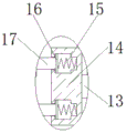
fig. 3 is a partially enlarged view of a portion a in fig. 1 according to the present invention.
In the figure: 1. a clamping box; 2. a hydraulic telescopic rod; 3. a first connection block; 4. a first fixed column; 5. a clamping block; 6. a clamping post; 7. a first splint; 8. a cylinder; 9. a second connecting block; 10. a second fixed column; 11. a fixed box; 12. a motor; 13. a rotating rod; 14. a fixing plate; 15. a spring; 16. a buffer plate; 17. a buffer column; 18. a second splint; 19. mounting blocks; 20. a first chute; 21. a first support column; 22. a first slider; 23. a second chute; 24. a second support column; 25. a second slider; 26. and (5) fixing blocks.
Detailed Description
The technical solutions in the embodiments of the present invention will be described clearly and completely with reference to the accompanying drawings in the embodiments of the present invention, and it is obvious that the described embodiments are only some embodiments of the present invention, not all embodiments. Based on the embodiments in the present invention, all other embodiments obtained by a person skilled in the art without creative work belong to the protection scope of the present invention.
The components of the present invention are all standard components or components known to those skilled in the art, and the structure and principle thereof can be known by the technical manual or by the conventional experimental method.
Referring to fig. 1-3, a cam plate producing and processing assembly comprises a clamping box 1, wherein the front side and the rear side of the two sides of the clamping box 1 are fixedly connected with mounting blocks 19, the surface of the mounting blocks 19 is provided with mounting through holes, the clamping box 1 can be better mounted and fixed by arranging the mounting blocks 19, the left side of the bottom of the clamping box 1 is provided with a first chute 20, the bottom of the first connecting block 3 is fixedly connected with a first supporting column 21, the bottom of the first supporting column 21 is fixedly connected with a first sliding block 22, one side of the first sliding block 22 away from the first supporting column 21 extends to the inner cavity of the first chute 20 and is movably connected with the first chute 20, the first connecting block 3 can be supported and the first connecting block 3 can better slide by arranging the first chute 20, the first supporting column 21 and the first sliding block 22, the right side of the bottom of the clamping box 1 is provided with a second chute 23, a second supporting column 24 is fixedly connected to the bottom of the second connecting block 9, a second slider 25 is fixedly connected to the bottom of the second supporting column 24, one side of the second slider 25, which is far away from the second supporting column 24, extends to an inner cavity of the second sliding groove 23 and is movably connected with the second sliding groove 23, the second supporting column 24 and the second slider 25 are arranged to support the second connecting block 9 and enable the second connecting block 9 to better slide, a hydraulic telescopic rod 2 is fixedly connected to the left side of the inner cavity of the clamping box 1, a first connecting block 3 is fixedly connected to the right end of the hydraulic telescopic rod 2, a first fixing column 4 is fixedly connected to the top of the first connecting block 3, the top of the first fixing column 4 penetrates through to the top of the clamping box 1 and is fixedly connected with a clamping block 5, a clamping column 6 is movably connected to the right side of the clamping block 5 through a bearing, a first clamping plate 7 is fixedly connected to the right end of the clamping column 6, the right side of the clamping box 1 is fixedly connected with an air cylinder 8, the output end of the air cylinder 8 penetrates through the inner cavity of the clamping box 1 and is fixedly connected with a second connecting block 9, the top of the second connecting block 9 is fixedly connected with a second fixing column 10, the top of the second fixing column 10 penetrates through the top of the clamping box 1 and is fixedly connected with a fixing box 11, the inner cavity of the fixing box 11 is fixedly connected with a motor 12, the right side of the motor 12 is fixedly connected with a fixing block 26, the right side of the fixing block 26 is fixedly connected with the right side of the inner cavity of the fixing box 11, the motor 12 can be better installed and fixed in the fixing box 11 by arranging the fixing block 26, the output end of the motor 12 is fixedly connected with a rotating rod 13, one end, far away from the motor 12, of the rotating rod 13 penetrates through the left side of the fixing box 11 and is fixedly connected with a fixing plate 14, the top and the bottom of one side, far away from the rotating rod 13, of the fixing plate 14 are respectively provided with a groove, and the inner cavity of the groove is fixedly connected with a spring 15, the left end of the spring 15 is fixedly connected with a buffer plate 16, one end of the buffer plate 16, which is far away from the spring 15, is fixedly connected with a buffer column 17, the left end of the buffer column 17 is fixedly connected with a second clamping plate 18, and a workpiece to be processed can be better clamped and fixed through the matching use of the clamping box 1, the hydraulic telescopic rod 2, the first connecting block 3, the first fixing column 4, the clamping block 5, the clamping column 6, the first clamping plate 7, the air cylinder 8, the second connecting block 9, the second fixing column 10, the fixing box 11, the motor 12, the rotating rod 13, the fixing plate 14, the spring 15, the buffer plate 16, the buffer column 17 and the second clamping plate 18, so that the problems that the cam disc in the prior art cannot be effectively clamped in the processing process, the production quality of products is poor, the precision is low, and the use requirements cannot be met are solved.
When in use, the clamping box 1 is installed and fixed on mechanical equipment through the installation block 19, a cam disc workpiece to be processed is placed between the first clamping plate 7 and the second clamping plate 18, the hydraulic telescopic rod 2 and the cylinder 8 are started, the hydraulic telescopic rod 2 drives the first connecting block 3 to move towards the right side, the first connecting block 3 drives the first clamping plate 7 to move towards the right side, the second connecting block 9 drives the second clamping plate 18 to move towards the left side, the first clamping plate 7 and the second clamping plate 18 clamp the cam disc workpiece, meanwhile, the second clamping plate 18 applies pressure to the buffer plate 16 to enable the buffer plate 16 to move towards the right side, the buffer plate 16 compresses the spring 15, impact generated during clamping is reduced, a cam plate workpiece is protected, the hydraulic telescopic rod 2 and the air cylinder 8 are stopped after clamping is fixed, then the motor 12 is started, the output end of the motor 12 drives the rotating rod 13 to rotate, and the rotating rod 13 drives the cam disc workpiece to rotate, so that the processing is convenient.
Although embodiments of the present invention have been shown and described, it will be appreciated by those skilled in the art that changes, modifications, substitutions and alterations can be made in these embodiments without departing from the principles and spirit of the invention, the scope of which is defined in the appended claims and their equivalents.
Claims (5)
1. A cam disc production and processing assembly comprises a clamping box (1), and is characterized in that: the left side of the inner cavity of the clamping box (1) is fixedly connected with a hydraulic telescopic rod (2), the right end of the hydraulic telescopic rod (2) is fixedly connected with a first connecting block (3), the top of the first connecting block (3) is fixedly connected with a first fixing column (4), the top of the first fixing column (4) penetrates through the top of the clamping box (1) and is fixedly connected with a clamping block (5), the right side of the clamping block (5) is movably connected with a clamping column (6) through a bearing, the right end of the clamping column (6) is fixedly connected with a first clamping plate (7), the right side of the clamping box (1) is fixedly connected with a cylinder (8), the output end of the cylinder (8) penetrates through the inner cavity of the clamping box (1) and is fixedly connected with a second connecting block (9), and the top of the second connecting block (9) is fixedly connected with a second fixing column (10), the top of second fixed column (10) runs through to the top of centre gripping case (1) and fixedly connected with fixed box (11), the inner chamber fixedly connected with motor (12) of fixed box (11), the output fixedly connected with bull stick (13) of motor (12), the one end that motor (12) were kept away from in bull stick (13) runs through to the left side of fixed box (11) and fixedly connected with fixed plate (14), the top and the bottom that bull stick (13) one side were kept away from in fixed plate (14) all set up flutedly, the inner chamber fixedly connected with spring (15) of recess, the left end fixedly connected with buffer board (16) of spring (15), the one end fixedly connected with buffering post (17) of spring (15) are kept away from in buffer board (16), the left end fixedly connected with second splint (18) of buffering post (17).
2. A cam plate production tooling assembly as claimed in claim 1 wherein: the front side and the rear side of the two sides of the clamping box (1) are fixedly connected with mounting blocks (19), and mounting through holes are formed in the surfaces of the mounting blocks (19).
3. A cam plate production tooling assembly as claimed in claim 1 wherein: first spout (20) have been seted up in the left side of centre gripping case (1) bottom, the first support column (21) of the bottom fixedly connected with of first connecting block (3), the first slider (22) of the bottom fixedly connected with of first support column (21), one side that first support column (21) were kept away from in first slider (22) extend to the inner chamber of first spout (20) and with first spout (20) swing joint.
4. A cam plate production tooling assembly as claimed in claim 1 wherein: second spout (23) have been seted up on the right side of centre gripping case (1) bottom, bottom fixedly connected with second support column (24) of second connecting block (9), bottom fixedly connected with second slider (25) of second support column (24), one side that second support column (24) were kept away from in second slider (25) extends to the inner chamber of second spout (23) and with second spout (23) swing joint.
5. A cam plate production tooling assembly as claimed in claim 1 wherein: the right side fixedly connected with fixed block (26) of motor (12), the right side of fixed block (26) and the right side fixed connection of fixed case (11) inner chamber.
Priority Applications (1)
| Application Number | Priority Date | Filing Date | Title |
|---|---|---|---|
| CN202022913529.6U CN214265285U (en) | 2020-12-08 | 2020-12-08 | Cam disc production and processing assembly |
Applications Claiming Priority (1)
| Application Number | Priority Date | Filing Date | Title |
|---|---|---|---|
| CN202022913529.6U CN214265285U (en) | 2020-12-08 | 2020-12-08 | Cam disc production and processing assembly |
Publications (1)
| Publication Number | Publication Date |
|---|---|
| CN214265285U true CN214265285U (en) | 2021-09-24 |
Family
ID=77779545
Family Applications (1)
| Application Number | Title | Priority Date | Filing Date |
|---|---|---|---|
| CN202022913529.6U Active CN214265285U (en) | 2020-12-08 | 2020-12-08 | Cam disc production and processing assembly |
Country Status (1)
| Country | Link |
|---|---|
| CN (1) | CN214265285U (en) |
Cited By (1)
| Publication number | Priority date | Publication date | Assignee | Title |
|---|---|---|---|---|
| CN114449885A (en) * | 2022-01-25 | 2022-05-06 | 常德市捷芯微电子科技有限公司 | A welded platform that is used for production of lamp area controller PCB board to use |
-
2020
- 2020-12-08 CN CN202022913529.6U patent/CN214265285U/en active Active
Cited By (2)
| Publication number | Priority date | Publication date | Assignee | Title |
|---|---|---|---|---|
| CN114449885A (en) * | 2022-01-25 | 2022-05-06 | 常德市捷芯微电子科技有限公司 | A welded platform that is used for production of lamp area controller PCB board to use |
| CN114449885B (en) * | 2022-01-25 | 2023-07-14 | 常德市捷芯微电子科技有限公司 | Welding platform for producing lamp strip controller PCB |
Similar Documents
| Publication | Publication Date | Title |
|---|---|---|
| CN214265285U (en) | Cam disc production and processing assembly | |
| CN112024654A (en) | Bending and punching device for aluminum alloy connecting plate | |
| CN204367085U (en) | Timber clamping device | |
| CN203918838U (en) | A kind of clamping device | |
| CN211889979U (en) | Clamping device is used in production of high accuracy auto parts | |
| CN105364587A (en) | Semi-automatic fixing clamp | |
| CN210436311U (en) | Board pressing machine | |
| CN104526775A (en) | Timber clamping device | |
| CN217513837U (en) | High-precision automatic hub machining device | |
| CN213732889U (en) | Precision plastic suction mould carving machine | |
| CN214161024U (en) | Stamping die with good positioning effect | |
| CN213968648U (en) | Improved stamping die for mobile phone back plate | |
| CN211728678U (en) | Low-noise mould polishing device | |
| CN213968942U (en) | Die casting die with shock-absorbing function | |
| CN210615820U (en) | Semi-solid aluminum alloy die casting tailing saw cuts anchor clamps | |
| CN211360333U (en) | Compound hardware mould of absorbing | |
| CN211890412U (en) | Water pump cover terminal surface flat grinding frock | |
| CN215033769U (en) | Lathe for processing niobium cup mold | |
| CN207289815U (en) | Hollow glass Special Fixture for Machining | |
| CN217750431U (en) | Clamping device for processing inner profile of thin-wall composite material conical part | |
| CN214110707U (en) | Slotting device for processing solid wood doors and windows | |
| CN220481360U (en) | Metal product processingequipment | |
| CN215788263U (en) | Tool for machining engine cylinder block | |
| CN216542741U (en) | Automobile air conditioner water heater radiator adds clamping apparatus | |
| CN214263998U (en) | Deep hole drill tool for cubic press machine |
Legal Events
| Date | Code | Title | Description |
|---|---|---|---|
| GR01 | Patent grant | ||
| GR01 | Patent grant |