CN214230362U - Automatic rotating dining table turntable device - Google Patents
Automatic rotating dining table turntable device Download PDFInfo
- Publication number
- CN214230362U CN214230362U CN202022679792.3U CN202022679792U CN214230362U CN 214230362 U CN214230362 U CN 214230362U CN 202022679792 U CN202022679792 U CN 202022679792U CN 214230362 U CN214230362 U CN 214230362U
- Authority
- CN
- China
- Prior art keywords
- gear ring
- ring body
- top cover
- motor
- control module
- Prior art date
- Legal status (The legal status is an assumption and is not a legal conclusion. Google has not performed a legal analysis and makes no representation as to the accuracy of the status listed.)
- Active
Links
Images


Landscapes
- Gear Transmission (AREA)
Abstract
The utility model discloses an automatic rotatory dining table carousel device, including the bottom, the top cap, the gear circle body, a control circuit who is used for driving gear circle body pivoted motor and is used for controlling motor, the bottom, the coincidence of the central point of top cap and gear circle body, the gear circle body is installed between bottom and top cap, the motor meets with the gear circle body, control circuit and motor electric connection, when the gear circle body receives motor drive, rotate as rotation center with its central point, drive the top cap when the gear circle body rotates and rotate, the bottom keeps static simultaneously. The utility model drives the gear ring body to rotate by the motor, and drives the top cover to rotate when the gear ring body rotates, thereby realizing the rotating function of the top cover and enabling dishes placed on the top cover to rotate along with the rotation of the top cover; this technical scheme is independent of the product of dining table, only need during the use directly with the carousel place on the dining table can, the cost is lower and convenient to use.
Description
Technical Field
The utility model relates to a food and beverage apparatus, more specifically say the utility model relates to an automatic rotatory dining table carousel device.
Background
Aiming at large-scale dining occasions, the dining table is provided with a turntable, and the rotation of the traditional turntable of the dining table needs to be controlled manually so as to be convenient for people on the dining table to select different dishes for eating. In order to make dining more convenient for people, a designer tries to make dishes on the turntable automatically rotate.
In order to achieve the purpose in the prior art, a commonly-adopted mode is to design a dining table capable of controlling automatic rotation of dishes, the technical scheme in the two patent documents is to reform the existing dining table, a turntable capable of rotating is arranged on the upper end face of the dining table, namely the turntable needs to be matched with the dining table, and the dining table is produced and sold simultaneously, wherein the patent document with the application number of 201710710250.8 and the patent document with the application number of 201810858939.X both disclose automatic rotation dining tables. Based on the prior technical scheme, related units need to replace the existing dining table for realizing the automatic rotation function of dishes, and the cost is huge.
SUMMERY OF THE UTILITY MODEL
An object of the utility model is to provide an automatic rotatory dining table carousel device to solve one or more technical problem that exist among the prior art, provide a profitable selection or create the condition at least.
The technical scheme adopted for solving the technical problems is as follows:
the utility model provides an automatic rotatory dining table carousel device, includes bottom, top cap, gear ring body, is used for the drive gear ring body pivoted motor and is used for controlling the control circuit of motor, the bottom top cap and the coincidence of the central point of gear ring body, gear ring body install the bottom with between the top cap, the motor meets with gear ring body, control circuit with motor electric connection, gear ring body receives during motor drive, it is rotatory to use its central point as the center of rotation, gear ring body drives when rotating the top cap rotates, simultaneously the bottom keeps static.
As a further improvement of the above technical solution, the gear ring body is detachably mounted between the bottom cover and the top cover, and when the gear ring body rotates, the top cover is driven to rotate by the friction force between the gear ring body and the top cover.
As a further improvement of the above technical solution, a plurality of first limiting columns are arranged on the upper end surface of the bottom cover, the plurality of first limiting columns are distributed in an annular array with a center point of the bottom cover as a center of a circle, the plurality of first limiting columns form a first limiting area, and the gear ring body is installed in the first limiting area;
the bottom of the gear ring body is provided with a plurality of first rolling connecting pieces, the first rolling connecting pieces are arranged at the bottom of the gear ring body in an annular array by taking the central point of the gear ring body as the center of a circle, and the gear ring body is contacted with the bottom cover through the first rolling connecting pieces.
As a further improvement of the above technical solution, a plurality of second limiting columns are arranged on the lower end surface of the top cover, the plurality of second limiting columns are distributed in an annular array with the center point of the top cover as a circle center, the plurality of second limiting columns form a second limiting area, and the gear ring body is installed in the second limiting area;
the top of the gear ring body is provided with a plurality of second rolling connecting pieces, the second rolling connecting pieces are arranged at the top of the gear ring body in an annular array mode by taking the central point of the gear ring body as the circle center, and the gear ring body is in contact with the top cover through the second rolling connecting pieces.
As a further improvement of the above technical solution, a first rib is radially and outwardly disposed at the bottom of the gear ring body, a second rib is radially and outwardly disposed at the top of the gear ring body, a first limit block is disposed on the first limit post of the bottom cover, a second limit block is disposed on the second limit post of the top cover, the first rib of the gear ring body is disposed below the first limit block of the bottom cover, and the second rib of the gear ring body is disposed above the second limit block of the top cover.
As a further improvement of the above technical solution, the bottom cover is provided with a first through hole, when the top cover rotates, the plurality of second limiting posts form a second moving track, and the first through hole of the bottom cover is arranged on the second moving track;
the top cover is provided with a second through hole, when the top cover rotates, the first limiting columns of the bottom cover form a first moving track relative to the top cover, and the second through hole of the top cover is arranged on the first moving track.
As a further improvement of the above technical solution, the control circuit includes:
the two motor interfaces are configured and used for being respectively connected with the motors;
the power interface is connected with the motor interface, and the power interface and the motor interface form a power-on loop;
the current direction control module is used for controlling the current direction input to the motor interface by the power interface;
the current amplitude control module is connected in series on the power-on loop and used for controlling the current amplitude input to the motor interface by the power interface;
the input module and the main control module;
the input module is connected with the input end of the main control module, and the output end of the main control module is respectively connected with the current direction control module and the current amplitude control module.
As a further improvement of the above technical solution, the current amplitude control module includes a switch tube and a push-pull driving circuit, the push-pull driving circuit is connected to an output end of the main control module, the push-pull driving circuit is connected to a gate of the switch tube, the push-pull driving circuit controls a conduction degree of the switch tube according to a voltage signal output by the main control module, and a source and a drain of the switch tube are respectively connected to the power-on circuit.
As a further improvement of the above technical solution, the input module includes a remote control receiver for receiving a transmission signal of an external remote control transmitter, the remote control receiver includes a wireless receiving chip with a model of SYN520R and a peripheral circuit thereof, the main control module includes a decoding control chip with a model of TCT6227 and a peripheral circuit thereof, and the decoding control chip is connected to the wireless receiving chip, the current amplitude control module, and the current direction control module, respectively.
As a further improvement of the above technical solution, the technical solution further includes a storage module, and the main control module is connected with the storage module.
The utility model has the advantages that: the utility model drives the gear ring body to rotate by the motor, and drives the top cover to rotate when the gear ring body rotates, thereby realizing the rotating function of the top cover and enabling dishes placed on the top cover to rotate along with the rotation of the top cover; this technical scheme is independent of the product of dining table, only need during the use directly with the carousel place on the dining table can, the cost is lower and convenient to use.
Drawings
The present invention will be further explained with reference to the drawings and examples;
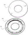
fig. 1 is a schematic view of the mechanical structure of the present invention (the bottom cover and the gear ring body are mounted together);
fig. 2 is a schematic diagram of the mechanical structure of the present invention in a discrete manner;
fig. 3 is a side view of the gear ring body of the present invention;
fig. 4 is a schematic diagram of the control circuit of the present invention.
Description of reference numerals:
100. the bottom cover comprises a bottom cover body 110, a first limiting column 120, a first limiting block 130, a first through hole 200, a top cover body 210, a second through hole 300, a gear ring body 310, a first rolling connecting piece 320, a second rolling connecting piece 330, a first convex edge 340 and a second convex edge.
Detailed Description
This section will describe in detail the embodiments of the present invention, preferred embodiments of the present invention are shown in the attached drawings, which are used to supplement the description of the text part of the specification with figures, so that one can intuitively and vividly understand each technical feature and the whole technical solution of the present invention, but they cannot be understood as the limitation of the protection scope of the present invention.
In the description of the present invention, it should be understood that the orientation or positional relationship indicated with respect to the orientation description, such as up, down, front, rear, left, right, etc., is based on the orientation or positional relationship shown in the drawings, and is only for convenience of description and simplification of description, and does not indicate or imply that the device or element referred to must have a specific orientation, be constructed and operated in a specific orientation, and thus, should not be construed as limiting the present invention.
In the description of the present invention, if words such as "a plurality" are used, the meaning is one or more, the meaning of a plurality of words is two or more, and the meaning of more than, less than, more than, etc. is understood as not including the number, and the meaning of more than, less than, more than, etc. is understood as including the number.
In the description of the present invention, unless there is an explicit limitation, the words such as setting, installation, connection, etc. should be understood in a broad sense, and those skilled in the art can reasonably determine the specific meanings of the above words in combination with the specific contents of the technical solution.
Referring to fig. 1, 2 and 3, a first embodiment of the present invention discloses an automatic revolving dining table, which includes a bottom cover 100, a top cover 200, a gear ring 300, a motor (not shown in the drawings) for driving the gear ring 300 to rotate, and a control circuit for controlling the motor, wherein central points of the bottom cover 100, the top cover 200, and the gear ring 300 are overlapped, the gear ring 300 is installed between the bottom cover 100 and the top cover 200, the motor is connected to the gear ring 300, the control circuit is electrically connected to the motor, when the gear ring 300 is driven by the motor, the central point of the gear ring rotates, when the gear ring 300 rotates, the top cover 200 is driven to rotate, and the bottom cover 100 remains still. In the practical application process, the turntable is placed on a dining table, then glass for containing dishes is placed on the turntable, the motor is used for driving the gear ring body 300 in the turntable to rotate during dining, and the gear ring body 300 drives the top cover 200 to rotate in the rotating process, so that the glass is rotated.
Compared with the prior art, this embodiment is a product independent of dining table, can use with all traditional dining table cooperations, relevant unit only needs purchase the product of this embodiment promptly, and need not to reform transform or replace original dining table, the cost is lower and convenient to use.
In a further preferred embodiment, the gear ring body 300 may be integrally formed with the top cover 200, or may be detachably mounted between the top cover 200 and the bottom cover 100. If the gear ring body 300 and the top cover 200 are integrally formed in this embodiment, the advantage is that the production is convenient, and the assembly process can be greatly simplified. If the gear ring body 300 of the present embodiment is detachably installed between the top cover 200 and the bottom cover 100, it is advantageous in that the maintenance is convenient in the future, the cost is low, and only the damaged parts need to be replaced. For the above two embodiments, in this embodiment, the gear ring body 300 is preferably detachably mounted between the bottom cover 100 and the top cover 200, and when the gear ring body 300 rotates, the top cover 200 is driven to rotate by the friction force between the gear ring body 300 and the top cover 200.
Further as a preferred embodiment, in this embodiment, the upper end surface of the bottom cover 100 is provided with a plurality of first limiting columns 110, the plurality of first limiting columns 110 are distributed in an annular array with a center point of the bottom cover 100 as a center, the plurality of first limiting columns 110 form a first limiting area, the gear ring body 300 is installed in the first limiting area, and the outer side of the gear ring body 300 is connected to each of the first limiting columns 110;
the bottom of the gear ring body 300 is provided with a plurality of first rolling connectors 310, the plurality of first rolling connectors 310 are arranged at the bottom of the gear ring body 300 in an annular array by taking a central point of the gear ring body 300 as a circle center, the gear ring body 300 is in contact with the bottom cover 100 through the plurality of first rolling connectors 310, and the first rolling connectors 310 may be rollers or balls.
Specifically, in this embodiment, a plurality of first rolling connectors 310 are disposed at the bottom of the gear ring body 300, and through the disposed first rolling connectors 310, the friction between the gear ring body 300 and the bottom cover 100 during the rotation of the gear ring body 300 is reduced, and the friction between the gear ring body 300 and the bottom cover 100 is reduced, which is helpful for reducing the specification requirement of the motor for driving the gear ring body 300 to rotate.
Further as a preferred embodiment, in this embodiment, a plurality of second limiting columns (not shown in the drawings) are disposed on the lower end surface of the top cover 200, the plurality of second limiting columns are distributed in an annular array with a center point of the top cover 200 as a center, the plurality of second limiting columns form a second limiting area, the gear ring body 300 is installed in the second limiting area, and the outer side of the gear ring body 300 is connected to each of the second limiting columns;
a plurality of second rolling connectors 320 are installed at the top of the gear ring body 300, the second rolling connectors 320 are arranged at the top of the gear ring body 300 in an annular array by using the central point of the gear ring body 300 as the center of a circle, the gear ring body 300 is in contact with the top cover 200 through the plurality of second rolling connectors 320, and the second rolling connectors 320 may be rollers or balls.
Further as a preferred implementation manner, in this embodiment, a first protruding rib 330 is radially and outwardly disposed at the bottom of the gear ring body 300, a second protruding rib 340 is radially and outwardly disposed at the top of the gear ring body 300, a first limiting block 120 is disposed on the first limiting column 110 of the bottom cover 100, a second limiting block (not shown in the drawings) is disposed on the second limiting column of the top cover 200, the first protruding rib 330 of the gear ring body 300 is disposed below the first limiting block 120 of the bottom cover 100, and the second protruding rib 340 of the gear ring body 300 is disposed above the second limiting block of the top cover 200. In this embodiment, the first stopper 120 may be mounted on the first stopper post 110 and the second stopper may be mounted on the second stopper post by screws, but other manners may be selected to implement the mounting operation of the first stopper 120 and the second stopper. In this embodiment, the first stopper 120 and the second stopper are provided, and the first rib 330 and the second rib 340 provided on the gear ring body 300 are combined, so that the top cover 200, the gear ring body 300, and the bottom cover 100 can be assembled together in a relatively fixed manner, and individual components are prevented from falling off during the movement of the turntable.
Further as a preferred embodiment, in this embodiment, in order to facilitate the installation of the first stopper 120 and the second stopper, in this embodiment, the bottom cover 100 is provided with a first through hole 130, the top cover 200 is provided with a second through hole 210, when the top cover 200 rotates, the plurality of second stopper posts form a second moving track, the first through hole 130 of the bottom cover 100 is arranged on the second moving track, when the top cover 200 rotates, the plurality of first stopper posts 110 of the bottom cover 100 form a first moving track relative to the top cover 200, and the second through hole 210 of the top cover 200 is arranged on the first moving track. In an actual assembling process, a relevant person mounts the first stopper 120 on the first stopper post 110 of the bottom cover 100 through the second through hole 210 of the top cover 200, and mounts the second stopper on the second stopper post of the top cover 200 through the first through hole 130 of the bottom cover 100.
In a further preferred embodiment, in the present embodiment, the shape and structure of the top cover 200 and the bottom cover 100 are identical.
Referring to fig. 4, in this embodiment, the control circuit includes:
the two motor interfaces are configured and used for being respectively connected with the motors;
the power interface is connected with the motor interface, and the power interface and the motor interface form a power-on loop;
the current direction control module is used for controlling the current direction input to the motor interface by the power interface;
the current amplitude control module is connected in series on the power-on loop and used for controlling the current amplitude input to the motor interface by the power interface;
the input module and the main control module;
the input module is connected with the input end of the main control module, and the output end of the main control module is respectively connected with the current direction control module and the current amplitude control module.
Specifically, in this embodiment, the current amplitude control module is arranged in the power-on loop formed by the motor interface and the power interface, and the current amplitude control module controls the current amplitude in the power-on loop according to the voltage signal output by the main control module, so as to realize the function of controlling the rotation speed of the motor.
Further as a preferred implementation manner, in this embodiment, the current amplitude control module includes a switch tube and a push-pull driving circuit, the push-pull driving circuit is connected to an output end of the main control module, the push-pull driving circuit is connected to a gate of the switch tube, the push-pull driving circuit controls a conduction degree of the switch tube according to a voltage signal output by the main control module, and a source and a drain of the switch tube are respectively connected to the power-on loop. The push-pull driving circuit comprises an NPN type triode Q1 and a PNP type triode Q2, the base electrode of the triode Q1 and the base electrode of the triode Q2 are connected with the two output ends of the main control module in a one-to-one correspondence mode, the emitting electrode of the triode Q1 is respectively connected with the emitting electrode of the triode Q2 and the grid electrode of the switching tube, the collecting electrode of the triode Q2 is grounded, and the collecting electrode of the triode Q1 is connected with a power interface.
Further as a preferred implementation manner, in this embodiment, the input module includes a remote control receiver for receiving a transmission signal of an external remote control transmitter, and the remote control receiver is connected to the main control module. Specifically, in this embodiment, the remote control receiver includes a wireless receiving chip with a model number of SYN520R and its peripheral circuits.
Further, as a preferred implementation manner, in this embodiment, the main control module includes a decoding control chip with a model of TCT6227 and a peripheral circuit thereof, and the decoding control chip is connected to the wireless receiving chip, the current amplitude control module, and the current direction control module, respectively. Specifically, the decoding control chip of this type in this embodiment is a learning-type decoding chip, and has the characteristics of high security, stable performance, low power consumption, and the like.
Further, as a preferred implementation manner, in this embodiment, the system further includes a storage module, and the main control module is connected to the storage module.
Further, as a preferred implementation manner, in this embodiment, the power supply module is further included, and the power supply module is connected to the power supply interface.
While the preferred embodiments of the present invention have been described in detail, it will be understood by those skilled in the art that the foregoing and various other changes, omissions and deviations in the form and detail thereof may be made without departing from the scope of this invention.
Claims (9)
1. The utility model provides an automatic rotatory dining table carousel device which characterized in that: the gear ring comprises a bottom cover (100), a top cover (200), a gear ring body (300), a motor and a control circuit, wherein the motor is used for driving the gear ring body (300) to rotate, the control circuit is used for controlling the motor, the central points of the bottom cover (100), the top cover (200) and the gear ring body (300) are overlapped, the gear ring body (300) is installed between the bottom cover (100) and the top cover (200), the motor is connected with the gear ring body (300), the control circuit is electrically connected with the motor, when the gear ring body (300) is driven by the motor, the central point of the gear ring body is used as a rotation center to rotate, the gear ring body (300) drives the top cover (200) to rotate when rotating, and meanwhile, the bottom cover (100) keeps static;
the control circuit includes:
the two motor interfaces are configured and used for being respectively connected with the motors;
the power interface is connected with the motor interface, and the power interface and the motor interface form a power-on loop;
the current direction control module is used for controlling the current direction input to the motor interface by the power interface;
the current amplitude control module is connected in series on the power-on loop and used for controlling the current amplitude input to the motor interface by the power interface;
the input module and the main control module;
the input module is connected with the input end of the main control module, and the output end of the main control module is respectively connected with the current direction control module and the current amplitude control module.
2. An automatic rotary dining table turntable device as claimed in claim 1, wherein: the gear ring body (300) is detachably arranged between the bottom cover (100) and the top cover (200), and when the gear ring body (300) rotates, the top cover (200) is driven to rotate by the friction force between the gear ring body (300) and the top cover (200).
3. An automatic rotary dining table turntable device as claimed in claim 2, wherein: the upper end face of the bottom cover (100) is provided with a plurality of first limiting columns (110), the first limiting columns (110) are distributed in an annular array by taking the central point of the bottom cover (100) as the center of a circle, the first limiting columns (110) form a first limiting area, and the gear ring body (300) is installed in the first limiting area;
a plurality of first rolling connectors (310) are mounted at the bottom of the gear ring body (300), and the gear ring body (300) is in contact with the bottom cover (100) through the plurality of first rolling connectors (310).
4. An automatic rotary dining table turntable device according to claim 3, wherein: a plurality of second limiting columns are arranged on the lower end face of the top cover (200), the second limiting columns are distributed in an annular array mode with the center point of the top cover (200) as the center of a circle, a second limiting area is formed by the second limiting columns, and the gear ring body (300) is installed in the second limiting area;
a plurality of second rolling connectors (320) are mounted at the top of the gear ring body (300), and the gear ring body (300) is in contact with the top cover (200) through the plurality of second rolling connectors (320).
5. An automatic rotary dining table turntable device according to claim 4, wherein: the gear ring is characterized in that a first convex edge (330) is radially and outwardly arranged at the bottom of the gear ring body (300), a second convex edge (340) is radially and outwardly arranged at the top of the gear ring body (300), a first limiting block (120) is arranged on a first limiting column (110) of the bottom cover (100), a second limiting block is arranged on a second limiting column of the top cover (200), the first convex edge (330) of the gear ring body (300) is arranged below the first limiting block (120) of the bottom cover (100), and the second convex edge (340) of the gear ring body (300) is arranged above the second limiting block of the top cover (200).
6. An automatic rotary dining table carousel as claimed in claim 5, wherein: the bottom cover (100) is provided with a first through hole (130), when the top cover (200) rotates, a plurality of second limiting columns form a second moving track, and the first through hole (130) of the bottom cover (100) is arranged on the second moving track;
the top cover (200) is provided with a second through hole (210), when the top cover (200) rotates, a plurality of first limiting columns (110) of the bottom cover (100) form a first moving track relative to the top cover (200), and the second through hole (210) of the top cover (200) is arranged on the first moving track.
7. An automatic rotary dining table turntable device as claimed in claim 1, wherein: the current amplitude control module comprises a switch tube and a push-pull drive circuit, the push-pull drive circuit is connected with the output end of the main control module, the push-pull drive circuit is connected with the grid electrode of the switch tube, the push-pull drive circuit controls the conduction degree of the switch tube according to a voltage signal output by the main control module, and the source electrode and the drain electrode of the switch tube are respectively connected into the power-on loop.
8. An automatic rotary dining table turntable device as claimed in claim 1, wherein: the input module comprises a remote control receiver for receiving transmission signals of an external remote control transmitter, the remote control receiver comprises a wireless receiving chip with the model of SYN520R and a peripheral circuit thereof, the main control module comprises a decoding control chip with the model of TCT6227 and a peripheral circuit thereof, and the decoding control chip is respectively connected with the wireless receiving chip, the current amplitude control module and the current direction control module.
9. An automatic rotary dining table turntable device as claimed in claim 1, wherein: the intelligent control system also comprises a storage module, and the main control module is connected with the storage module.
Priority Applications (1)
| Application Number | Priority Date | Filing Date | Title |
|---|---|---|---|
| CN202022679792.3U CN214230362U (en) | 2020-11-18 | 2020-11-18 | Automatic rotating dining table turntable device |
Applications Claiming Priority (1)
| Application Number | Priority Date | Filing Date | Title |
|---|---|---|---|
| CN202022679792.3U CN214230362U (en) | 2020-11-18 | 2020-11-18 | Automatic rotating dining table turntable device |
Publications (1)
| Publication Number | Publication Date |
|---|---|
| CN214230362U true CN214230362U (en) | 2021-09-21 |
Family
ID=77733008
Family Applications (1)
| Application Number | Title | Priority Date | Filing Date |
|---|---|---|---|
| CN202022679792.3U Active CN214230362U (en) | 2020-11-18 | 2020-11-18 | Automatic rotating dining table turntable device |
Country Status (1)
| Country | Link |
|---|---|
| CN (1) | CN214230362U (en) |
Cited By (1)
| Publication number | Priority date | Publication date | Assignee | Title |
|---|---|---|---|---|
| CN112401484A (en) * | 2020-11-18 | 2021-02-26 | 江西盈克电子科技有限公司 | Automatic rotating dining table turntable device |
-
2020
- 2020-11-18 CN CN202022679792.3U patent/CN214230362U/en active Active
Cited By (1)
| Publication number | Priority date | Publication date | Assignee | Title |
|---|---|---|---|---|
| CN112401484A (en) * | 2020-11-18 | 2021-02-26 | 江西盈克电子科技有限公司 | Automatic rotating dining table turntable device |
Similar Documents
| Publication | Publication Date | Title |
|---|---|---|
| CN214230362U (en) | Automatic rotating dining table turntable device | |
| CN104963881A (en) | Intelligent electric fan | |
| CN106653438B (en) | Interactive intelligent panel, key structure and manufacturing method of light guide column of interactive intelligent panel | |
| US20180358838A1 (en) | Solar outdoor furniture | |
| CN204851716U (en) | Intelligence electric fan | |
| CN204480610U (en) | There is the multi-media advertisement box of screen cleaning mechanism | |
| CN214230292U (en) | Rotary dining table turntable and rotary dining table turntable device | |
| CN112401484A (en) | Automatic rotating dining table turntable device | |
| KR101869854B1 (en) | A rotating and charging device of portable electric fan and a method thereof | |
| CN102588314A (en) | Electric fan | |
| CN213754363U (en) | Automatic rotating dining table turntable and motor control circuit thereof | |
| CN107886700A (en) | A kind of rotating type strip shows multifunctional remote controlller | |
| CN202677605U (en) | Draw curtain and display device | |
| CN205208068U (en) | Liquid crystal disply device supporting component and liquid crystal disply device | |
| CN213815243U (en) | Multifunctional display device of distributed industrial control system | |
| CN110631167B (en) | Controller, electric control equipment and control method of controller | |
| CN210485992U (en) | Controller and electric control equipment | |
| CN201035722Y (en) | Novel computer remote controller and receiver | |
| CN210106928U (en) | Domestic hidden intelligent ball-type camera | |
| CN205751227U (en) | A kind of IR remote controller | |
| CN203351023U (en) | Passive infrared transmission device based on Enocean | |
| CN219020494U (en) | Dining table turntable | |
| CN207602021U (en) | A kind of rotating type strip shows multifunctional remote controlller | |
| CN211431575U (en) | Dining table turntable structure with cleaning function | |
| CN216773111U (en) | Remote controller key structure capable of switching key symbols |
Legal Events
| Date | Code | Title | Description |
|---|---|---|---|
| GR01 | Patent grant | ||
| GR01 | Patent grant | ||
| EE01 | Entry into force of recordation of patent licensing contract | ||
| EE01 | Entry into force of recordation of patent licensing contract |
Assignee: Jiangxi Yingke Hotel Supplies Co.,Ltd. Assignor: JIANGXI YINGKE ELECTRONIC TECHNOLOGY Co.,Ltd. Contract record no.: X2023980036927 Denomination of utility model: An automatic rotating Lazy Susan device Granted publication date: 20210921 License type: Common License Record date: 20230625 |