CN214226111U - Energy-conserving water gauge of electricity generation certainly based on NB communication - Google Patents
Energy-conserving water gauge of electricity generation certainly based on NB communication Download PDFInfo
- Publication number
- CN214226111U CN214226111U CN202023186866.6U CN202023186866U CN214226111U CN 214226111 U CN214226111 U CN 214226111U CN 202023186866 U CN202023186866 U CN 202023186866U CN 214226111 U CN214226111 U CN 214226111U
- Authority
- CN
- China
- Prior art keywords
- casing
- fixed
- baffle
- energy
- fixedly arranged
- Prior art date
- Legal status (The legal status is an assumption and is not a legal conclusion. Google has not performed a legal analysis and makes no representation as to the accuracy of the status listed.)
- Active
Links
Images


Abstract
The utility model relates to a long-range water gauge technical field just discloses a from energy-conserving water gauge of electricity generation based on NB communication, including casing and instrument, the equal fixed connecting pipe that is provided with in casing ear nail both sides, the instrument is fixed to be set up in the lower extreme surface of casing, the fixed baffle that is provided with in inside of casing, the last fixed surface of baffle is provided with hydroelectric generator, the below of baffle is provided with the circuit board, the surface integration of circuit board is provided with super capacitor and NB-IoT communication module, hydroelectric generator passes through wire and super capacitor electric connection, the lower surface of casing is provided with the bottom, the lower surface both sides both ends of casing are the fixed block that is provided with all, a plurality of draw-in grooves have been seted up to the lateral wall of bottom, and are a plurality of the fixed block all with the draw-in groove phase-match that corresponds. The utility model discloses can carry out from the electricity generation, energy-concerving and environment-protective, and the installation is dismantled conveniently, is convenient for maintain and maintain inside.
Description
Technical Field
The utility model relates to a long-range water gauge technical field especially relates to a from energy-conserving water gauge of electricity generation based on NB communication.
Background
The narrowband Internet of Things (NB-IoT) becomes an important branch of the Internet of everything, the NB-IoT is constructed in a cellular network, only the bandwidth of about 180kHz is consumed, and the NB-IoT can be directly deployed in a GSM network, a UMTS network or an LTE network so as to reduce the deployment cost and realize smooth upgrade.
The energy-conserving water gauge of traditional communication generally needs external power source to use, and the abandonment electrical apparatus of change can produce serious pollution if handling badly, is not conform to energy-concerving and environment-protective original intention, need regularly dismantle the maintenance to the communication water gauge for guaranteeing data record's accuracy moreover, and present communication water gauge all adopts a plurality of bolt-up to connect, and it is inconvenient to dismantle, great reduction maintenance efficiency.
SUMMERY OF THE UTILITY MODEL
The utility model aims at solving the problem that the energy-conserving water gauge of communication generally needs external power source to use among the prior art, the easy polluted environment of battery of change and inconvenient dismantlement are maintained, and the energy-conserving water gauge of electricity generation certainly based on the NB communication that proposes.
In order to achieve the above purpose, the utility model adopts the following technical scheme:
a self-generating energy-saving water meter based on NB communication comprises a shell and an instrument, wherein connecting pipes are fixedly arranged on two sides of an ear nail of the shell, the instrument is fixedly arranged on the lower end surface of the shell, a partition is fixedly arranged in the shell, a hydroelectric generator is fixedly arranged on the upper surface of the partition, a circuit board is arranged below the partition, a super capacitor and an NB-IoT communication module are integrally arranged on the surface of the circuit board, the hydroelectric generator is electrically connected with the super capacitor through a wire, a bottom cover is arranged on the lower surface of the shell, fixed blocks are fixedly arranged on two sides of the lower surface of the shell, a plurality of clamping grooves are formed in the side wall of the bottom cover, the fixed blocks are matched with the corresponding clamping grooves, rotating shafts are rotatably arranged on two sides of the lower surface of the bottom cover, and stop rods are fixedly sleeved on the rod walls of the rotating shafts, the lateral wall of a plurality of fixed block all sets up flutedly, and is a plurality of the outside one end of pin all extends to the inside of the recess that corresponds, the lower surface middle part of bottom is provided with and drives a plurality ofly pin pivoted rotary mechanism.
Preferably, rotary mechanism includes worm wheel and worm, and is a plurality of the worm wheel is all fixed cup joints in the upper end pole wall of the pivot that corresponds, the lower surface middle part of bottom is fixed and is provided with two connecting plates, two the worm all rotates through antifriction bearing and corresponding connecting plate to be connected, two the worm all is connected with the worm wheel meshing that corresponds, two connecting rod fixed connection is passed through to the inboard one end of worm, the fixed cover of middle-end of connecting rod has connect the gear, the lower surface middle part both sides of bottom are all fixed and are provided with solid fixed ring, two gu fixed ring's inside is slided and is provided with the rack, the rack is connected with gear engagement, the left end of rack is fixed and is provided with the baffle.
Preferably, the fixed fool-proof post that is provided with of inside wall of casing, the fool-proof groove has been seted up to the lateral wall of circuit board, the fool-proof post matches with the fool-proof groove.
Preferably, the lateral wall of instrument is fixed and is provided with a plurality of lamp pearls.
Preferably, the rod wall at the left end of the rack is movably sleeved with a spring, and two ends of the spring are respectively and fixedly connected with the corresponding baffle and the fixing ring.
Preferably, a pull ring is fixedly arranged at the right end of the rack.
Compared with the prior art, the utility model provides a from energy-conserving water gauge of electricity generation based on NB communication possesses following beneficial effect:
1. this energy-conserving water gauge of electricity generation from electricity based on NB communication drives hydroelectric generator electricity generation through the power that the water produced and realizes the power supply of circuit board, and super capacitor realizes the storage and the release of energy, and the rivers are realized the power supply of circuit board by super capacitor when not changing to need not external power supply, energy-concerving and environment-protective.
2. This energy-conserving water gauge from electricity generation based on NB communication through the pulling pull ring for the rack drives gear revolve, thereby makes the connecting rod drive two worms and rotates, and two worms drive a plurality of worm wheels and rotate, can drive a plurality of pin rotations, thereby makes a plurality of pin leave from the recess that corresponds, thereby conveniently dismantles the bottom, conveniently maintains and maintains water gauge inside promptly.
The part that does not relate to in the device all is the same with prior art or can adopt prior art to realize, the utility model discloses can carry out from the electricity generation, energy-concerving and environment-protective, and the installation is dismantled conveniently, is convenient for maintain and maintain inside.
Drawings
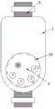
Fig. 1 is a schematic structural view of a self-generating energy-saving water meter based on NB communication;
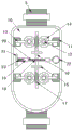
FIG. 2 is a schematic view of the internal structure of FIG. 1;
FIG. 3 is a schematic view of the internal structure of FIG. 2;
fig. 4 is a schematic bottom view of fig. 1.
In the figure: the device comprises a shell 1, a meter 2, a connecting pipe 3, a hydroelectric generator 4, a lead 5, a circuit board 6, a super capacitor 7, an 8NB-IoT communication module, a foolproof post 9, a bottom cover 10, a fixing block 11, a rotating shaft 12, a stop lever 13, a worm wheel 14, a connecting plate 15, a connecting rod 16, a worm 17, a gear 18, a fixing ring 19, a rack 20, a baffle 21, a pull ring 22, a spring 23 and a lamp bead 24.
Detailed Description
The technical solutions in the embodiments of the present invention will be described clearly and completely with reference to the accompanying drawings in the embodiments of the present invention, and it is obvious that the described embodiments are only some embodiments of the present invention, not all embodiments.
In the description of the present invention, it is to be understood that the terms "upper", "lower", "front", "rear", "left", "right", "top", "bottom", "inner", "outer", and the like indicate orientations or positional relationships based on the orientations or positional relationships shown in the drawings, and are only for convenience of description and simplicity of description, and do not indicate or imply that the device or element being referred to must have a particular orientation, be constructed and operated in a particular orientation, and therefore, should not be construed as limiting the present invention.
Referring to fig. 1-4, a self-generating energy-saving water meter based on NB communication comprises a housing 1 and an instrument 2, wherein connecting pipes 3 are fixedly arranged on both sides of an ear nail of the housing 1, the instrument 2 is fixedly arranged on the lower end surface of the housing 1, a partition is fixedly arranged inside the housing 1, a hydroelectric generator 4 is fixedly arranged on the upper surface of the partition, a circuit board 6 is arranged below the partition, a super capacitor 7 and an NB-IoT communication module 8 are integrally arranged on the surface of the circuit board 6, the hydroelectric generator 4 is electrically connected with the super capacitor 7 through a wire 5, a bottom cover 10 is arranged on the lower surface of the housing 1, fixing blocks 11 are fixedly arranged on both sides of the lower surface of the housing 1, a plurality of clamping grooves are formed in the side wall of the bottom cover 10, the fixing blocks 11 are matched with the corresponding clamping grooves, rotating shafts 12 are rotatably arranged on both sides of the lower surface of the bottom cover 10, and blocking rods 13 are fixedly sleeved on the rod walls of the rotating shafts 12, the lateral wall of a plurality of fixed blocks 11 all sets up flutedly, and the outside one end of a plurality of pin 13 all extends to the inside of the recess that corresponds, and the lower surface middle part of bottom 10 is provided with the rotary mechanism that drives a plurality of pin 13 pivoted.
The rotating mechanism comprises worm wheels 14 and worms 17, the worm wheels 14 are fixedly sleeved on the upper end rod walls of the corresponding rotating shafts 12, two connecting plates 15 are fixedly arranged in the middle of the lower surface of the bottom cover 10, the two worms 17 are rotatably connected with the corresponding connecting plates 15 through rolling bearings, the two worms 17 are respectively meshed with the corresponding worm wheels 14, one ends of the inner sides of the two worms 17 are fixedly connected through a connecting rod 16, a gear 18 is fixedly sleeved at the middle end of the connecting rod 16, fixing rings 19 are fixedly arranged on two sides of the middle of the lower surface of the bottom cover 10, racks 20 are slidably arranged in the two fixing rings 19, the racks 20 are meshed with the gear 18, and a baffle 21 is fixedly arranged at the left end of each rack 20.
The fixed fool-proof post 9 that is provided with of inside wall of casing 1, the fool-proof groove has been seted up to the lateral wall of circuit board 6, and fool-proof post 9 matches with the fool-proof groove, and the convenience is spacing to circuit board 6.
The fixed a plurality of lamp pearls 24 that are provided with of lateral wall of instrument 2 makes things convenient for night to observe.
The left end rod wall of the rack 20 is movably sleeved with a spring 23, and two ends of the spring 23 are respectively and fixedly connected with the corresponding baffle 21 and the fixing ring 19, so that the rack 20 is convenient to reset quickly.
A pull ring 22 is fixedly arranged at the right end of the rack 20, so that the rack 20 can be conveniently pulled.
The utility model discloses in, during the use, power drive hydroelectric generator 4 electricity generation realization circuit board 6's power supply through the water production, report data through NB-IoT communication module 8, super capacitor 7 realizes storage and release of energy, the power supply of circuit board 6 is realized by super capacitor 7 when the rivers do not change, thereby need not external power supply, energy-concerving and environment-protective, when needs dismantle the water gauge and maintain, pulling pull ring 22, make rack 20 drive gear 18 and rotate, thereby make connecting rod 16 drive two worms 17 and rotate, two worms 17 drive a plurality of worm wheel 14 and rotate, can drive a plurality of pin 13 and rotate, thereby make a plurality of pin 13 leave from the recess that corresponds, can separate casing 1 and bottom 10 this moment, the convenience is maintained and is maintained inside the water gauge promptly.
The above, only be the concrete implementation of the preferred embodiment of the present invention, but the protection scope of the present invention is not limited thereto, and any person skilled in the art is in the technical scope of the present invention, according to the technical solution of the present invention and the utility model, the concept of which is equivalent to replace or change, should be covered within the protection scope of the present invention.
Claims (6)
1. The utility model provides an energy-conserving water gauge of electricity generation certainly based on NB communication, includes casing (1) and instrument (2), its characterized in that, casing (1) ear nail both sides all are fixed and are provided with connecting pipe (3), instrument (2) are fixed to be set up in the lower extreme surface of casing (1), the inside of casing (1) is fixed and is provided with the baffle, the last fixed surface of baffle is provided with hydroelectric generator (4), the below of baffle is provided with circuit board (6), the surface integration of circuit board (6) is provided with super capacitor (7) and NB-IoT communication module (8), hydroelectric generator (4) passes through wire (5) and super capacitor (7) electric connection, the lower surface of casing (1) is provided with bottom (10), the lower surface both sides both ends of casing (1) all are fixed and are provided with fixed block (11), a plurality of draw-in grooves have been seted up to the lateral wall of bottom (, it is a plurality of fixed block (11) all with the draw-in groove phase-match that corresponds, the lower surface both sides both ends of bottom (10) all rotate and are provided with pivot (12), and are a plurality of the pole wall of pivot (12) all fixedly has cup jointed pin (13), and is a plurality of the lateral wall of fixed block (11) is all seted up flutedly, and is a plurality of the outside one end of pin (13) all extends to the inside of the recess that corresponds, the lower surface middle part of bottom (10) is provided with and drives a plurality ofly pin (13) pivoted rotary mechanism.
2. The self-generating energy-saving water meter based on NB communication according to claim 1, wherein the rotating mechanism comprises worm gears (14) and worms (17), the worm gears (14) are all fixedly sleeved on the upper end rod wall of the corresponding rotating shaft (12), two connecting plates (15) are fixedly arranged in the middle of the lower surface of the bottom cover (10), the two worms (17) are rotatably connected with the corresponding connecting plates (15) through rolling bearings, the two worms (17) are respectively meshed with the corresponding worm gears (14), one ends of the inner sides of the two worms (17) are fixedly connected through connecting rods (16), gears (18) are fixedly sleeved at the middle ends of the connecting rods (16), fixing rings (19) are fixedly arranged on two sides of the middle part of the lower surface of the bottom cover (10), and racks (20) are slidably arranged in the two fixing rings (19), the rack (20) is meshed with the gear (18), and a baffle (21) is fixedly arranged at the left end of the rack (20).
3. The self-generating energy-saving water meter based on NB communication according to claim 1, wherein a fool-proof post (9) is fixedly arranged on the inner side wall of the housing (1), a fool-proof groove is formed on the side wall of the circuit board (6), and the fool-proof post (9) is matched with the fool-proof groove.
4. The self-generating energy-saving water meter based on NB communication according to claim 1, wherein a plurality of lamp beads (24) are fixedly arranged on the side wall of the meter (2).
5. The self-generating energy-saving water meter based on NB communication according to claim 2, wherein a spring (23) is movably sleeved on the left end rod wall of the rack (20), and two ends of the spring (23) are respectively and fixedly connected with the corresponding baffle (21) and the fixing ring (19).
6. The self-generating energy-saving water meter based on NB communication according to claim 2, wherein a pull ring (22) is fixedly arranged at the right end of the rack (20).
Priority Applications (1)
| Application Number | Priority Date | Filing Date | Title |
|---|---|---|---|
| CN202023186866.6U CN214226111U (en) | 2020-12-26 | 2020-12-26 | Energy-conserving water gauge of electricity generation certainly based on NB communication |
Applications Claiming Priority (1)
| Application Number | Priority Date | Filing Date | Title |
|---|---|---|---|
| CN202023186866.6U CN214226111U (en) | 2020-12-26 | 2020-12-26 | Energy-conserving water gauge of electricity generation certainly based on NB communication |
Publications (1)
| Publication Number | Publication Date |
|---|---|
| CN214226111U true CN214226111U (en) | 2021-09-17 |
Family
ID=77705501
Family Applications (1)
| Application Number | Title | Priority Date | Filing Date |
|---|---|---|---|
| CN202023186866.6U Active CN214226111U (en) | 2020-12-26 | 2020-12-26 | Energy-conserving water gauge of electricity generation certainly based on NB communication |
Country Status (1)
| Country | Link |
|---|---|
| CN (1) | CN214226111U (en) |
-
2020
- 2020-12-26 CN CN202023186866.6U patent/CN214226111U/en active Active
Similar Documents
| Publication | Publication Date | Title |
|---|---|---|
| CN108807743A (en) | A kind of new energy car battery protective device | |
| CN112082128A (en) | Rainwater and wind power generation's sunshade rain cooling intelligence street lamp | |
| CN214226111U (en) | Energy-conserving water gauge of electricity generation certainly based on NB communication | |
| CN111425980A (en) | Ventilation equipment with from power generation function | |
| CN210706959U (en) | Dustproof and rainproof function's electric pile that fills | |
| CN114006501B (en) | Motor rotating shaft rotating speed control system with safety alarm | |
| CN111146406B (en) | Rapid curing and drying system and curing and drying method for storage battery pole plate | |
| CN211702652U (en) | High-low box with protection function | |
| CN209928586U (en) | Mountain torrent disaster monitoring and early warning power supply device | |
| CN210957518U (en) | Box wall structure of wind power generation box-type substation | |
| CN210629174U (en) | Efficient wind power generation treasured that charges | |
| CN207834843U (en) | A kind of rain-proof cabinet | |
| CN216414938U (en) | Electric power measurement and control equipment for solar energy collection | |
| CN212463383U (en) | Port vehicle information acquisition equipment | |
| CN214043875U (en) | Energy storage battery pack convenient to detach for user | |
| CN220980827U (en) | Hydroelectric inspection robot | |
| CN111120214A (en) | Movable three-dimensional wind power generation device | |
| CN217282778U (en) | New energy power generation device | |
| CN215498635U (en) | Generator cooling device for wind power generation | |
| CN214591269U (en) | Ocean current monitoring device | |
| CN215675021U (en) | Photovoltaic lighting device for water conservancy and hydropower | |
| CN214851093U (en) | Energy storage device of nearly zero energy consumption building community | |
| CN213363282U (en) | Biomass energy drying equipment | |
| CN215633510U (en) | Brake device of wind driven generator | |
| CN214944742U (en) | Wind generating set is inside inspection device in labour blade |
Legal Events
| Date | Code | Title | Description |
|---|---|---|---|
| GR01 | Patent grant | ||
| GR01 | Patent grant |