CN214200933U - Geotechnical engineering test device - Google Patents
Geotechnical engineering test device Download PDFInfo
- Publication number
- CN214200933U CN214200933U CN202120120775.8U CN202120120775U CN214200933U CN 214200933 U CN214200933 U CN 214200933U CN 202120120775 U CN202120120775 U CN 202120120775U CN 214200933 U CN214200933 U CN 214200933U
- Authority
- CN
- China
- Prior art keywords
- test tube
- piston
- connecting pin
- geotechnical
- test device
- Prior art date
- Legal status (The legal status is an assumption and is not a legal conclusion. Google has not performed a legal analysis and makes no representation as to the accuracy of the status listed.)
- Expired - Fee Related
Links
Images

Abstract
The utility model provides a testing device for geotechnical engineering belongs to the experimental technical field of ground, including base, experimental pipe, piston and connecting pin. The leakage fluid dram has been seted up at the top of base, and the leakage fluid dram is located the inboard of spacing seat. The test tube is used for storing rock soil samples, the test tube is slidably arranged in the limiting seat, the bottom of the test tube is provided with a connecting plate, and the connecting plate is provided with a plurality of liquid discharge holes communicated with the liquid discharge port; and the test tube is used for storing rock soil samples. The piston slides along the inner wall of the test tube and is used for extruding the rock soil sample, and a plurality of liquid outlet holes are formed in the piston. The connecting pin is detachably connected to the test tube; the connecting pin penetrates through the test tube and is used for abutting against the top surface of the piston when the piston resets, and the piston drives the test tube to slide out of the limiting seat through the connecting pin. The utility model provides a test device for geotechnical engineering is convenient for accomplish taking out of back test tube at the experiment through setting up the connecting pin, has simplified work step, has improved experimental efficiency.
Description
Technical Field
The utility model belongs to the technical field of the geotechnical test, more specifically say, relate to testing arrangement for geotechnical engineering.
Background
The research on rock mechanical properties, constitutive relation, strength criteria, failure mechanism and the like is the most basic and most core content in the fields of rock mechanics and engineering, and the related research is mainly carried out through uniaxial, biaxial and conventional triaxial tests at present. Need take out the ground sample with the container that is used for depositing the ground sample after experimental completion in the lump, because reasons such as operating space is limited and weight is heavier, the process of taking out wastes time and energy, influences work efficiency.
SUMMERY OF THE UTILITY MODEL
An object of the utility model is to provide a testing device for geotechnical engineering aims at solving because reasons such as operating space is limited and weight is heavier, takes out the in-process of ground sample and being used for depositing ground sample container and wastes time and energy, influences work efficiency's problem.
In order to achieve the above object, the utility model adopts the following technical scheme: provided is a test device for geotechnical engineering, including:
the liquid discharging device comprises a base, a liquid discharging port and a liquid discharging device, wherein a limiting seat is arranged on the upper end surface of the base, and the liquid discharging port is positioned on the inner side of the limiting seat;
the test tube is used for storing rock and soil samples, the test tube is slidably arranged in the limiting seat, a connecting plate is arranged at the bottom of the test tube, and a plurality of liquid discharge holes communicated with the liquid discharge port are formed in the connecting plate;
the piston slides along the inner wall of the test tube and is used for extruding a rock-soil sample, and a plurality of liquid outlet holes are formed in the piston;
the connecting pin is detachably connected to the test tube; the connecting pin penetrates through the test tube and is used for abutting against the top surface of the piston when the piston is reset, and the piston drives the test tube to slide out of the limiting seat through the connecting pin.
As another embodiment of the application, the connecting pin is in plug fit with the top of the test tube.
As another embodiment of the present application, the number of the connecting pins is two, and the two connecting pins are distributed on two opposite sides of the test tube.
As another embodiment of the application, the end part of the connecting pin is provided with a limiting block used for abutting against the outer wall of the test tube.
As another embodiment of the present application, a driving member is connected to the piston; the driving piece is arranged above the test tube through a support and used for driving the piston to move.
As another embodiment of the application, the bottom surface of the piston and the top surface of the connecting plate are both provided with water permeable layers.
As another embodiment of the application, the connecting plate and the top of the base are arranged at intervals to form a circulation cavity, and the circulation cavity is used for communicating the liquid discharge port and the plurality of liquid discharge holes.
As another embodiment of the present application, the top surface of the piston is provided with a water absorbent material for absorbing liquid.
As another embodiment of this application, follow the circumference joint of piston has the sealing washer, the sealing washer be used for sealing the piston with the clearance between the test tube inner wall.
As another embodiment of the application, the limiting seat is welded and fixed on the base.
The utility model provides a geotechnical engineering uses test device's beneficial effect lies in: compared with the prior art, the utility model discloses the leakage fluid dram has been seted up at the top of base among the testing device for the geotechnical engineering, and is equipped with spacing seat at the up end of base. When the device is used practically, firstly, rock soil samples are filled in the test tube, then the test tube slides into the limiting seat, and the piston is in sliding fit with the inner wall of the test tube. And in the process that the piston extrudes the rock-soil sample, liquid in the rock-soil sample is respectively discharged from the liquid outlet hole on the piston and the liquid outlet hole on the connecting plate. After the detection is finished, the connecting pin is connected to the test tube, and the connecting pin penetrates through the test tube, so that when the piston is reset, the connecting pin abuts against the top surface of the piston. The motion of piston can drive the test tube motion through the connecting pin finally, makes the test tube follow spacing internal slipping out finally. In this application, through setting up the connecting pin, be convenient for accomplish taking out of back test tube at the experiment, simplified work step, improved experimental efficiency.
Drawings
In order to more clearly illustrate the technical solutions of the embodiments of the present invention, the drawings required for the embodiments or the prior art descriptions will be briefly described below, and it is obvious that the drawings in the following description are only some embodiments of the present invention, and it is obvious for those skilled in the art to obtain other drawings without creative efforts.
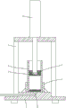
Fig. 1 is a schematic structural diagram of a testing apparatus for geotechnical engineering when extruding a geotechnical sample according to an embodiment of the present invention;
fig. 2 is the utility model provides a second when taking out the test tube geotechnical sample test device for structural schematic diagram who provides.
In the figure: 1. a base; 2. a liquid discharge port; 3. a support; 4. a drive member; 5. a piston; 6. a test tube; 7. A water absorbing material; 8. a limiting seat; 9. a connecting pin; 10. a limiting block; 11. a liquid outlet hole; 12. a drain hole; 13. A connecting plate.
Detailed Description
In order to make the technical problem, technical solution and advantageous effects to be solved by the present invention more clearly understood, the following description is given in conjunction with the accompanying drawings and embodiments to illustrate the present invention in further detail. It should be understood that the specific embodiments described herein are merely illustrative of the invention and are not intended to limit the invention.
Referring to fig. 1 and 2, a testing apparatus for geotechnical engineering according to the present invention will now be described. Geotechnical engineering uses test device, including base 1, test tube 6, piston 5 and connecting pin 9. The upper end face of the base 1 is provided with a limiting seat 8, the top of the base 1 is provided with a liquid outlet 2, and the liquid outlet 2 is located on the inner side of the limiting seat 8. The test tube 6 is used for storing rock soil samples, the test tube 6 is slidably arranged in the limiting seat 8, a connecting plate 13 is arranged at the bottom of the test tube 6, and a plurality of liquid discharge holes 12 communicated with the liquid discharge port 2 are formed in the connecting plate 13. The piston 5 slides along the inner wall of the test tube 6 and is used for extruding rock and soil samples, and the piston 5 is provided with a plurality of liquid outlet holes 11. The connecting pin 9 is detachably connected to the test tube 6; the connecting pin 9 penetrates through the test tube 6 and is used for abutting against the top surface of the piston 5 when the piston 5 resets, and the piston 5 drives the test tube 6 to slide out of the limiting seat 8 through the connecting pin 9.
The utility model provides a geotechnical engineering uses test device's beneficial effect lies in: compared with the prior art, the utility model discloses leakage fluid dram 2 has been seted up at base 1's top among the testing device for the geotechnical engineering, and is equipped with spacing seat 8 at base 1's up end. When in actual use, firstly, the rock soil sample is filled in the test tube 6, then the test tube 6 slides into the limiting seat 8, and the piston 5 is in sliding fit with the inner wall of the test tube 6. Liquid in the rock soil sample is respectively discharged from the liquid outlet hole 11 on the piston 5 and the liquid outlet hole 12 on the connecting plate 13 in the process that the piston 5 presses the rock soil sample. When the test is completed, the connection pin 9 is connected to the test tube 6, and since the connection pin 9 penetrates the test tube 6, the connection pin 9 abuts against the top surface of the piston 5 when the piston 5 is reset. The movement of the piston 5 finally drives the test tube 6 to move through the connecting pin 9, and finally the test tube 6 slides out of the limiting seat 8. In this application, through setting up connecting pin 9, be convenient for accomplish taking out of back test tube 6 at the experiment, simplified work step, improved experimental efficiency.
As a specific embodiment of the testing device for geotechnical engineering provided by the utility model, please refer to fig. 1 and 2, the connecting pin 9 is in insertion fit with the top of the testing tube 6. After the rock and soil sample is detected, the test tube 6 needs to be taken out of the limiting seat 8. The test tube 6 and the rock soil sample are heavy and are not convenient to take out manually, so the test tube 6 is connected with a connecting pin 9. The top of the test tube 6 can be provided with a through hole for inserting and matching with the connecting pin 9, and the connecting pin 9 is inserted and matched with the through hole. The piston 5 is used for extruding the rock soil sample when moving downwards, and the piston 5 is reset when moving upwards. When the piston 5 resets, the connecting pin 9 is abutted, the test tube 6 is driven to move through the connecting pin 9, and therefore the test tube 6 is driven to slide out of the limiting seat 8.
As a specific implementation manner of the testing device for geotechnical engineering provided by the utility model, please refer to fig. 2, the quantity of connecting pin 9 is two, and two connecting pins 9 distribute in the relative both sides of test tube 6. Since the test tube 6 and the rock sample have heavy mass, if only one connecting pin 9 is provided, the test tube 6 may have a force deviating from the axial direction of the test tube 6 on the stopper seat 8 when the piston 5 is reset, and the test tube 6 may be inclined after the piston 5 takes out the test tube 6. For this purpose, the connecting pins 9 are two in number and are distributed on opposite sides of the test tube 6.
As a specific embodiment of the testing device for geotechnical engineering, please refer to fig. 2, the tip of connecting pin 9 is equipped with and is used for leaning on stopper 10 at 6 outer walls of test tube. In order to stabilize the connecting pin 9 at a predetermined position of the test tube 6, a stopper 10 is provided at an end of the connecting pin 9 located outside the test tube 6, and the stopper 10 is integrally formed with the connecting pin 9. The connecting pin 9 may be replaced by a bolt.
Because reasons such as manufacturing error and piston 5 vibrations in the motion process for the effort of piston 5 to test tube 6 has the axial component of skew test tube 6, consequently in order to can stabilize test tube 6, spacing seat 8 welded fastening is on base 1 in this application, through increasing the joint strength between spacing seat 8 and the base 1, with the stability of assurance test tube 6 relative position.
As a specific embodiment of the testing apparatus for geotechnical engineering provided by the present invention, please refer to fig. 1 and 2, the piston 5 is connected to the driving member 4; the driving piece 4 is arranged above the test tube 6 through the bracket 3 and is used for driving the piston 5 to move. Because great effort is needed when the rock soil sample is extruded, and the relative position of the piston 5 relative to the movement of the base 1 needs to be accurately controlled, a support 3 is arranged above the base 1, an avoiding hole for taking out and placing the test tube 6 is formed in the support 3, the piston 5 is connected with a driving piece 4, the driving piece 4 drives the piston 5 to move, and the driving piece 4 can be any one of a hydraulic cylinder, an air cylinder or an electric push rod, preferably, the hydraulic cylinder can be selected.
As a specific embodiment of the testing apparatus for geotechnical engineering provided by the present invention, please refer to fig. 1 and 2, the bottom surface of the piston 5 and the top surface of the connecting plate 13 are both provided with a permeable layer. In this application, the piston 5 is required to move to compress the soil sample in the test tube 6. Although the apertures of the liquid outlet holes 11 formed in the piston 5 and the liquid outlet holes 12 formed in the connecting plate 13 are small, in the process that the rock soil sample is extruded, the rock soil sample is inevitably extruded from the liquid outlet holes 11 and the liquid outlet holes 12, so that the final detection result is inaccurate. A water permeable layer is thus provided on both the top surface of the connecting plate 13 and the bottom surface of the piston 5. The permeable layer is used for enabling liquid to pass through, but has a certain barrier effect on rock and soil samples.
As a specific implementation manner of the testing device for geotechnical engineering provided by the utility model, please refer to fig. 1 and fig. 2, connecting plate 13 sets up and forms the circulation chamber with the top interval of base 1, and the circulation chamber is used for intercommunication leakage fluid dram 2 and a plurality of outage 12. If the bottom surface of connecting plate 13 direct butt on base 1, then can avoid plugging part leakage fluid dram 12 for the liquid that extrudes can't flow into in the leakage fluid dram 2 smoothly, consequently connecting plate 13 sets up with base 1 interval certain distance in this application, with the formation circulation chamber, makes the liquid that extrudes all can converge at leakage fluid dram 2 department through the circulation chamber.
As a specific embodiment of the testing apparatus for geotechnical engineering provided by the present invention, please refer to fig. 1 and 2, the top surface of the piston 5 is disposed on the water absorption material 7 for absorbing liquid. For the rock soil sample with large water content, in order to collect the liquid, a liquid discharge pipe is arranged in the base 1 in a penetrating way, one end of the liquid discharge pipe is communicated with the collecting barrel, the other end of the liquid discharge pipe extends upwards and is communicated with the liquid discharge port 2, and partial liquid extruded from the rock soil sample flows into the liquid discharge pipe through the liquid discharge port 2.
The piston 5 can overflow liquid in the process of extruding the rock soil sample, so that the rod of the piston 5 is sleeved with the water absorbing material 7. The water absorbing material 7 can be an annular structure with an opening on one side, the bottom surface of the water absorbing material 7 abuts against the top surface of the piston 5, and overflowed liquid is finally absorbed by the water absorbing material 7 through the liquid discharge holes 12 in the process that the piston 5 extrudes the rock soil sample. The absorbent material 7 may be a sponge or other absorbent material. The water absorbing material 7 is taken out before the piston 5 is reset so as to avoid the connecting pin 9.
As the utility model provides a concrete implementation of test device for geotechnical engineering has the sealing washer along piston 5's circumference joint, and the sealing washer is used for the clearance between 6 inner walls of sealed piston 5 and test tube. An annular groove is formed in the circumferential direction of the piston 5, and the sealing ring can be directly bonded in the annular groove to ensure the stability of the relative position of the sealing ring.
As a specific embodiment of the testing device for geotechnical engineering provided by the utility model, please refer to fig. 1 and 2, the spacing seat 8 is welded and fixed on the base 1. The main function of the limiting seat 8 is to limit the position of the test tube 6, since the piston 5 enters from the top of the test tube 6 and presses the rock and soil sample in the test tube 6. And through setting up spacing seat 8 to set up the spacing hole with test tube 6 sliding fit on spacing seat 8, in order to guarantee the accuracy of test tube 6 for piston 5 position when detecting at every turn.
The above description is only exemplary of the present invention and should not be construed as limiting the present invention, and any modifications, equivalents and improvements made within the spirit and principles of the present invention are intended to be included within the scope of the present invention.
Claims (10)
1. Test device for geotechnical engineering, its characterized in that includes:
the liquid discharging device comprises a base, a liquid discharging port and a liquid discharging device, wherein a limiting seat is arranged on the upper end surface of the base, and the liquid discharging port is positioned on the inner side of the limiting seat;
the test tube is used for storing rock and soil samples, the test tube is slidably arranged in the limiting seat, a connecting plate is arranged at the bottom of the test tube, and a plurality of liquid discharge holes communicated with the liquid discharge port are formed in the connecting plate;
the piston slides along the inner wall of the test tube and is used for extruding a rock-soil sample, and a plurality of liquid outlet holes are formed in the piston;
the connecting pin is detachably connected to the test tube; the connecting pin penetrates through the test tube and is used for abutting against the top surface of the piston when the piston is reset, and the piston drives the test tube to slide out of the limiting seat through the connecting pin.
2. The geotechnical test device according to claim 1, wherein said connecting pin is fitted to the top of said test tube by insertion.
3. The geotechnical test device according to claim 2, wherein the number of the connecting pins is two, and the two connecting pins are disposed at opposite sides of the test tube.
4. The geotechnical engineering test device according to claim 2, wherein the end of the connecting pin is provided with a stopper for abutting against the outer wall of the test tube.
5. The geotechnical test device according to claim 1, wherein a driving member is connected to said piston; the driving piece is arranged above the test tube through a support and used for driving the piston to move.
6. The geotechnical test device according to claim 1, wherein the bottom surface of said piston and the top surface of said connecting plate are provided with water permeable layers.
7. The geotechnical test device according to claim 1, wherein said connection plate is spaced apart from the top of said base and forms a flow-through chamber for communicating said drain port with said plurality of drain holes.
8. The geotechnical test device according to claim 1, wherein said piston has a top surface provided with a water-absorbing material for absorbing liquid.
9. The geotechnical engineering test device according to claim 1, wherein a seal ring is engaged along a circumferential direction of the piston, and the seal ring is used for sealing a gap between the piston and an inner wall of the test tube.
10. The geotechnical engineering test device according to claim 1, wherein said limit seat is welded and fixed to said base.
Priority Applications (1)
| Application Number | Priority Date | Filing Date | Title |
|---|---|---|---|
| CN202120120775.8U CN214200933U (en) | 2021-01-22 | 2021-01-22 | Geotechnical engineering test device |
Applications Claiming Priority (1)
| Application Number | Priority Date | Filing Date | Title |
|---|---|---|---|
| CN202120120775.8U CN214200933U (en) | 2021-01-22 | 2021-01-22 | Geotechnical engineering test device |
Publications (1)
| Publication Number | Publication Date |
|---|---|
| CN214200933U true CN214200933U (en) | 2021-09-14 |
Family
ID=77636470
Family Applications (1)
| Application Number | Title | Priority Date | Filing Date |
|---|---|---|---|
| CN202120120775.8U Expired - Fee Related CN214200933U (en) | 2021-01-22 | 2021-01-22 | Geotechnical engineering test device |
Country Status (1)
| Country | Link |
|---|---|
| CN (1) | CN214200933U (en) |
-
2021
- 2021-01-22 CN CN202120120775.8U patent/CN214200933U/en not_active Expired - Fee Related
Similar Documents
| Publication | Publication Date | Title |
|---|---|---|
| WO2020048185A2 (en) | Apparatus design and method for using rock true triaxial loading test system to develop fractured rock mass anisotrophic seepage test | |
| CN102979505B (en) | Well cementation cement sheath performance simulation experiment device and experiment method | |
| CN209129563U (en) | Core in situ shifts cabin | |
| CN202305262U (en) | Encapsulated coal sample sampler | |
| CN214200933U (en) | Geotechnical engineering test device | |
| CN111321896A (en) | Sleeve grouting construction defect detection and control device and method | |
| CN201859140U (en) | Sample injection device of liquid phase automatic sample injector | |
| CN203502409U (en) | Pressure chamber for tester with high temperature expansibility and permeability | |
| CN206832420U (en) | A kind of single port pressure testing device for large diameter pipeline | |
| CN210863260U (en) | Closed sampling and returning device for flowing medium | |
| CN210090109U (en) | Automatic disc type sampler | |
| CN207042501U (en) | Portable automatic detection kit | |
| CN218157460U (en) | Highway road surface infiltration check out test set | |
| CN203461799U (en) | Pneumatic filling machine | |
| CN109115554A (en) | River sewage sampler | |
| CN207408161U (en) | The disposable automatic subpackaging sampler bag of hydrology-water quality | |
| CN112304846A (en) | Engineering building material waterproof detection device and monitoring method thereof | |
| CN209271493U (en) | A kind of medicine detection pipettor | |
| CN208568755U (en) | A kind of floated real-time water quality detecting device | |
| CN106989872B (en) | Black plastic leakage detection device of filter | |
| CN111502596A (en) | Extrusion device for replacing slurry during drilling and water pressing and construction process | |
| CN111337412A (en) | Multifunctional automatic flexible wall penetration tester and testing method thereof | |
| CN211602646U (en) | On-spot grout sampling device that uses | |
| CN205844349U (en) | A kind of sample adding device of breast milk composition analyser | |
| CN213995957U (en) | Reagent storage box for environmental detection |
Legal Events
| Date | Code | Title | Description |
|---|---|---|---|
| GR01 | Patent grant | ||
| GR01 | Patent grant | ||
| CF01 | Termination of patent right due to non-payment of annual fee |
Granted publication date: 20210914 Termination date: 20220122 |
|
| CF01 | Termination of patent right due to non-payment of annual fee |