CN214200073U - Measuring device for building engineering technology - Google Patents
Measuring device for building engineering technology Download PDFInfo
- Publication number
- CN214200073U CN214200073U CN202120429061.5U CN202120429061U CN214200073U CN 214200073 U CN214200073 U CN 214200073U CN 202120429061 U CN202120429061 U CN 202120429061U CN 214200073 U CN214200073 U CN 214200073U
- Authority
- CN
- China
- Prior art keywords
- measuring instrument
- base
- engineering
- motor
- backup pad
- Prior art date
- Legal status (The legal status is an assumption and is not a legal conclusion. Google has not performed a legal analysis and makes no representation as to the accuracy of the status listed.)
- Expired - Fee Related
Links
- 238000005516 engineering process Methods 0.000 title description 7
- 238000000034 method Methods 0.000 claims abstract description 4
- 238000010276 construction Methods 0.000 claims description 13
- 238000005259 measurement Methods 0.000 abstract description 18
- 230000008901 benefit Effects 0.000 description 3
- 230000004048 modification Effects 0.000 description 3
- 238000012986 modification Methods 0.000 description 3
- 238000010586 diagram Methods 0.000 description 2
- 230000002035 prolonged effect Effects 0.000 description 1
Images


Abstract
The utility model discloses a measuring device for building engineering technique, concretely relates to building engineering measures technical field, including base, rotor plate, backup pad and engineering measuring instrument, the rotor plate top is equipped with four electric putter, the motor arrangement groove has been seted up to the base bottom, the fixed motor that is equipped with of motor arrangement inslot portion, the fixed dwang that is equipped with of output shaft of motor, the backup pad top is equipped with two grip blocks. The utility model discloses a setting can the pivoted rotor plate with can height-adjusting's electric putter, can be very convenient carry out the adjustment of height, angle and direction to engineering measuring instrument for engineering measuring instrument's measurement is more comprehensive, more convenient, and getting of engineering measuring instrument is put and is changed comparatively convenient and fast, has improved measuring efficiency, and engineering measuring instrument can carry alone, carries comparatively conveniently, is difficult for producing the vibration, can prolong engineering measuring instrument's life.
Description
Technical Field
The embodiment of the utility model provides a relate to building engineering and measure technical field, concretely relates to measuring device for building engineering technique.
Background
The measurement of the construction engineering is the measurement work of the construction engineering during the design, construction stage and as-built use, and the measurement of the construction engineering is very important in the construction engineering, and the requirement of the measurement of the construction engineering on the accuracy is very high.
The existing measuring device for the building engineering technology fixes an engineering measuring instrument on a supporting device, so that the measuring angle and the measuring direction are not convenient to adjust, when different measuring instruments are needed, the instrument is troublesome to replace, the instrument is inconvenient to carry after measurement, and when the instrument is carried with the supporting device, the instrument is easy to vibrate, parts in the instrument are easy to damage, and the service life of the instrument is shortened.
SUMMERY OF THE UTILITY MODEL
Therefore, the embodiment of the utility model provides a measuring device for construction engineering, through setting up the rotatable rotating plate and the electric push rod that can adjust the height, can very conveniently carry out the adjustment of height, angle and direction to the engineering measuring instrument, make the measurement of engineering measuring instrument more comprehensive, more convenient, and the getting of engineering measuring instrument is put and is changed comparatively convenient and fast, improved the efficiency of measurement, and the engineering measuring instrument can be carried alone, it is more convenient to carry, difficult to produce the vibration, can lengthen the life of engineering measuring instrument, in order to solve the prior art because the measuring device for construction engineering technology all fixes the engineering measuring instrument on the strutting arrangement and leads to the inconvenient adjustment of measurement angle and measurement direction, and when needing to use different measuring instruments, it is comparatively troublesome to change the instrument, the carrying of the instrument after the measurement is comparatively inconvenient, when the instrument is carried together with the supporting device, the instrument is easy to vibrate, the parts in the instrument are easy to damage, and the service life of the instrument is shortened.
In order to achieve the above object, the embodiment of the present invention provides the following technical solutions: a measuring device for building engineering technology comprises a base, a rotating plate, a supporting plate and an engineering measuring instrument, wherein the rotating plate is arranged at the top end of the base, the supporting plate is arranged at the top end of the rotating plate, the engineering measuring instrument is arranged at the top end of the supporting plate, four electric push rods are arranged at the top end of the rotating plate, two ends of each electric push rod are movably connected with the top end of the rotating plate and the bottom end of the supporting plate through hinged supports, a motor accommodating groove is formed in the bottom end of the base, a motor is fixedly arranged in the motor accommodating groove, a rotating rod is fixedly arranged on an output shaft of the motor, one end of the rotating rod penetrates through the top end of the base and is fixedly connected with the bottom end of the rotating plate, one end of the rotating rod is rotatably connected with the top end of the base through a bearing, two clamping plates are arranged at the top end of the supporting plate, anti-skid pads are fixedly arranged on the inner sides of the clamping plates, and the inner sides of the two anti-skid pads are respectively contacted with the front end and the top end of the engineering measuring instrument, the spout has been seted up on the backup pad top, the inside slider that is equipped with of spout, the inside threaded rod that is equipped with of spout, threaded rod one end is passed two sliders and backup pad front end and is extended to the backup pad front side, all through threaded connection and screw thread opposite direction between threaded rod and two sliders, all rotate through the bearing between threaded rod both ends and the spout inner wall and be connected.
Furthermore, a rotating handle is fixedly arranged at one end of the threaded rod and is arranged on the front side of the supporting plate.
Furthermore, a level meter is arranged on the supporting plate and is arranged on one side of the sliding groove.
Further, an annular sliding groove is formed in the top end of the base and is formed in the outer side of the motor placing groove, an annular sliding block is arranged inside the annular sliding groove, and the top end of the annular sliding block is fixedly connected with the bottom end of the rotating plate.
Furthermore, a handrail is fixedly arranged on one side of the base.
Furthermore, four brake wheels are fixedly arranged at the bottom end of the base, and the motor containing groove is formed among the four brake wheels.
The embodiment of the utility model provides a have following advantage:
the utility model fixes the engineering measuring instrument on the top of the supporting plate by rotating the rotating handle, when measuring the data in the horizontal direction, the heights of the four electric push rods are adjusted, the observation level meter adjusts the supporting plate and the engineering measuring instrument to the horizontal position, when measuring in different directions, the output shaft of the motor drives the supporting plate and the engineering measuring instrument to rotate, when measuring in different angles, the heights of the four electric push rods are respectively adjusted, thus the angles between the supporting plate and the engineering measuring instrument and the horizontal direction can be adjusted, after the measurement is finished, the engineering measuring instrument is taken down by reversely rotating the rotating handle, compared with the prior art, the height, angle and direction of the engineering measuring instrument can be conveniently adjusted, the measurement of the engineering measuring instrument is more comprehensive and more convenient, and the taking, putting and replacing of the engineering measuring instrument are more convenient and rapid, the efficiency of measurement is improved, and engineering measuring instrument can carry alone, and it is more convenient to carry, is difficult for producing the vibration, can prolong engineering measuring instrument's life.
Drawings
In order to more clearly illustrate the embodiments of the present invention or the technical solutions in the prior art, the drawings used in the description of the embodiments or the prior art will be briefly described below. It should be apparent that the drawings in the following description are merely exemplary, and that other embodiments can be derived from the drawings provided by those of ordinary skill in the art without inventive effort.
The structure, ratio, size and the like shown in the present specification are only used for matching with the content disclosed in the specification, so as to be known and read by people familiar with the technology, and are not used for limiting the limit conditions which can be implemented by the present invention, so that the present invention has no technical essential significance, and any structure modification, ratio relationship change or size adjustment should still fall within the scope which can be covered by the technical content disclosed by the present invention without affecting the efficacy and the achievable purpose of the present invention.
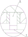
Fig. 1 is a schematic view of the overall structure provided by the present invention;
fig. 2 is a schematic left sectional view of the support plate according to the present invention;
fig. 3 is an enlarged schematic structural diagram of a in fig. 1 according to the present invention;
fig. 4 is an enlarged schematic structural diagram of B in fig. 1 according to the present invention;
in the figure: the device comprises a base 1, a rotating plate 2, a supporting plate 3, an engineering measuring instrument 4, an electric push rod 5, a motor 6 arranging groove, a motor 7, a rotating rod 8, a clamping plate 9, a non-slip mat 10, a sliding groove 11, a sliding block 12, a threaded rod 13, a rotating handle 14, a level meter 15, an annular sliding groove 16, an annular sliding block 17, an armrest 18 and a brake wheel 19.
Detailed Description
The present invention is described in terms of specific embodiments, and other advantages and benefits of the present invention will become apparent to those skilled in the art from the following disclosure. Based on the embodiments in the present invention, all other embodiments obtained by a person skilled in the art without creative work belong to the protection scope of the present invention.
Referring to the attached drawings 1-4 of the specification, the measuring device for the building engineering technology of the embodiment comprises a base 1, a rotating plate 2, a supporting plate 3 and an engineering measuring instrument 4, wherein the rotating plate 2 is arranged at the top end of the base 1, the supporting plate 3 is arranged at the top of the rotating plate 2, the engineering measuring instrument 4 is arranged at the top end of the supporting plate 3, four electric push rods 5 are arranged at the top end of the rotating plate 2, two ends of each electric push rod 5 are movably connected with the top end of the rotating plate 2 and the bottom end of the supporting plate 3 through hinges, a motor accommodating groove 6 is formed in the bottom end of the base 1, a motor 7 is fixedly arranged in the motor accommodating groove 6, a rotating rod 8 is fixedly arranged on an output shaft of the motor 7, one end of the rotating rod 8 penetrates through the top end of the base 1 and is fixedly connected with the bottom end of the rotating plate 2, one end of the rotating rod 8 is rotatably connected with the top end of the base 1 through a bearing, 3 tops of backup pad are equipped with two grip blocks 9, the inboard fixed slipmat 10 that is equipped with of grip block 9, two slipmat 10 inboard contacts with engineering measuring instrument 4's front and back end and top respectively, spout 11 has been seted up on 3 tops of backup pad, 11 inside sliders 12 that are equipped with of spout, 11 inside threaded rod 13 that are equipped with of spout, 13 one end of threaded rod is passed two sliders 12 and 3 front ends of backup pad and is extended to 3 front sides of backup pad, all through threaded connection and screw thread opposite direction between threaded rod 13 and two sliders 12, all rotate through the bearing and be connected between 13 both ends of threaded rod and the 11 inner walls of spout.
Furthermore, one end of the threaded rod 13 is fixedly provided with a rotating handle 14, and the rotating handle 14 is arranged on the front side of the support plate 3, so that the threaded rod 13 is driven to rotate conveniently.
Further, a level gauge 15 is arranged on the support plate 3, and the level gauge 15 is arranged on one side of the sliding groove 11, so that the support plate 3 can be conveniently adjusted to the horizontal direction.
Further, annular sliding groove 16 has been seted up on base 1 top, annular sliding groove 16 establishes in the motor arrangement groove 6 outside, annular sliding groove 16 is inside to be equipped with annular slider 17, annular slider 17 top and rotor plate 2 bottom fixed connection are convenient for rotor plate 2's steady rotation.
Further, a handrail 18 is fixedly arranged on one side of the base 1, so that the measuring device can be pushed to move conveniently.
Furthermore, four brake wheels 19 are fixedly arranged at the bottom end of the base 1, and the motor accommodating groove 6 is formed among the four brake wheels 19, so that the measuring device can be moved conveniently.
The implementation scenario is specifically as follows: the engineering measuring instrument 4 is placed on the top end of the supporting plate 3, the rotating handle 14 is rotated, the rotating handle 14 drives the threaded rod 13 to rotate, due to the threaded connection between the threaded rod 13 and the sliding block 12, the sliding block 12 moves inwards along with the rotation of the threaded rod 13, the sliding block 12 drives the clamping plate 9 and the anti-slip mat 10 to move inwards, the clamping plate 9 and the anti-slip mat 10 can fix the engineering measuring instrument 4 on the top end of the supporting plate 3, when data in the horizontal direction needs to be measured, the heights of four electric push rods 5 are adjusted, the supporting plate 3 and the engineering measuring instrument 4 are adjusted to the horizontal position by observing the level gauge 15, when different directions need to be measured, the motor 7 is started, the output shaft of the motor 7 drives the rotating rod 8 to rotate, the rotating rod 8 drives the rotating plate 2 to rotate, the rotating plate 2 drives the supporting plate 3 and the engineering measuring instrument 4 to rotate through the electric push rods 5, so that different directions can be measured, when different angles are required to be measured, the heights of the four electric push rods 5 are respectively adjusted, so that the angles between the supporting plate 3 and the engineering measuring instrument 4 and the horizontal direction can be adjusted, different angles can be measured, after the measurement is finished, the engineering measuring instrument 4 is taken down through the reverse rotation rotating handle 14, so that the engineering measuring instrument 4 is convenient to carry, the utility model can conveniently adjust the height, the angle and the direction of the engineering measuring instrument 4 by arranging the rotatable rotating plate 2 and the electric push rods 5 with adjustable heights, so that the measurement of the engineering measuring instrument 4 is more comprehensive and more convenient, the taking and the placing and the replacement of the engineering measuring instrument 4 are more convenient and rapid, the measuring efficiency is improved, the engineering measuring instrument 4 can be carried independently, the carrying is more convenient, the vibration is not easy to generate, and the service life of the engineering measuring instrument 4 can be prolonged, this embodiment has specifically solved among the prior art measuring device for building engineering technique all fixes engineering measuring instrument on strutting arrangement, is not convenient for adjust measurement angle and measurement direction like this, and when needing to use different measuring instrument, changes the instrument comparatively troublesome, and the carrying of measuring back instrument is also comparatively inconvenient, when carrying with strutting arrangement together, produces the vibration easily, and this damages the inside part of instrument easily, reduces the problem of the life of instrument.
Although the invention has been described in detail with respect to the general description and the specific embodiments, it will be apparent to those skilled in the art that modifications and improvements can be made based on the invention. Therefore, such modifications and improvements are intended to be within the scope of the invention as claimed.
Claims (6)
1. The utility model provides a measuring device for building engineering technique, includes base (1), rotor plate (2), backup pad (3) and engineering measuring instrument (4), establish on base (1) top rotor plate (2), establish at rotor plate (2) top backup pad (3), engineering measuring instrument (4) are established on backup pad (3) top, its characterized in that: the top end of the rotating plate (2) is provided with four electric push rods (5), the two ends of each electric push rod (5) are movably connected with the top end of the rotating plate (2) and the bottom end of the supporting plate (3) through hinged supports, the bottom end of the base (1) is provided with a motor accommodating groove (6), a motor (7) is fixedly arranged in the motor accommodating groove (6), an output shaft of the motor (7) is fixedly provided with a rotating rod (8), one end of the rotating rod (8) penetrates through the top end of the base (1) and is fixedly connected with the bottom end of the rotating plate (2), one end of the rotating rod (8) is rotatably connected with the top end of the base (1) through a bearing, the top end of the supporting plate (3) is provided with two clamping plates (9), anti-skid pads (10) are fixedly arranged on the inner sides of the clamping plates (9), and the inner sides of the two anti-skid, spout (11) have been seted up on backup pad (3) top, spout (11) inside is equipped with slider (12), spout (11) inside is equipped with threaded rod (13), two slider (12) and backup pad (3) front end are passed and are extended to backup pad (3) front side to threaded rod (13) one end, all through threaded connection and screw thread opposite direction between threaded rod (13) and two slider (12), all rotate through the bearing between threaded rod (13) both ends and spout (11) inner wall and be connected.
2. A measuring device for construction engineering according to claim 1, characterized in that: one end of the threaded rod (13) is fixedly provided with a rotating handle (14), and the rotating handle (14) is arranged on the front side of the supporting plate (3).
3. A measuring device for construction engineering according to claim 1, characterized in that: a level gauge (15) is arranged on the supporting plate (3), and the level gauge (15) is arranged on one side of the sliding groove (11).
4. A measuring device for construction engineering according to claim 1, characterized in that: annular chute (16) have been seted up on base (1) top, establish in the motor arrangement groove (6) outside annular chute (16), annular chute (16) inside is equipped with annular slider (17), annular slider (17) top and rotor plate (2) bottom fixed connection.
5. A measuring device for construction engineering according to claim 1, characterized in that: a handrail (18) is fixedly arranged on one side of the base (1).
6. A measuring device for construction engineering according to claim 1, characterized in that: four brake wheels (19) are fixedly arranged at the bottom end of the base (1), and the motor containing groove (6) is formed among the four brake wheels (19).
Priority Applications (1)
| Application Number | Priority Date | Filing Date | Title |
|---|---|---|---|
| CN202120429061.5U CN214200073U (en) | 2021-02-27 | 2021-02-27 | Measuring device for building engineering technology |
Applications Claiming Priority (1)
| Application Number | Priority Date | Filing Date | Title |
|---|---|---|---|
| CN202120429061.5U CN214200073U (en) | 2021-02-27 | 2021-02-27 | Measuring device for building engineering technology |
Publications (1)
| Publication Number | Publication Date |
|---|---|
| CN214200073U true CN214200073U (en) | 2021-09-14 |
Family
ID=77639604
Family Applications (1)
| Application Number | Title | Priority Date | Filing Date |
|---|---|---|---|
| CN202120429061.5U Expired - Fee Related CN214200073U (en) | 2021-02-27 | 2021-02-27 | Measuring device for building engineering technology |
Country Status (1)
| Country | Link |
|---|---|
| CN (1) | CN214200073U (en) |
-
2021
- 2021-02-27 CN CN202120429061.5U patent/CN214200073U/en not_active Expired - Fee Related
Similar Documents
| Publication | Publication Date | Title |
|---|---|---|
| CN210664295U (en) | Device for measuring conical surface angle of part | |
| CN214200073U (en) | Measuring device for building engineering technology | |
| CN212620670U (en) | Electric measuring instrument | |
| CN212300299U (en) | Gauge measuring device with marking function for subway construction | |
| CN214093813U (en) | Adjustable measurement and control instrument | |
| CN214842985U (en) | Device for measuring flatness of fan blade | |
| CN214372302U (en) | Profile measuring instrument | |
| CN212843466U (en) | Bearing ring size detection equipment | |
| CN209978860U (en) | Grinding size measuring tool | |
| CN214368779U (en) | Support for surveying instrument capable of improving photographic surveying and mapping precision | |
| CN209495848U (en) | A kind of bearing of compressor detection device convenient for adjusting | |
| CN218511941U (en) | Manual test dynamic balancing machine for hard support measurement | |
| CN206601109U (en) | A kind of fast calibrating device of three coordinate measuring machine parts measurement | |
| CN219121400U (en) | Laser measuring device for house measurement | |
| CN211808697U (en) | Higher mathematics is with multi-functional portable drawing apparatus | |
| CN218895768U (en) | Three-coordinate measurement auxiliary device | |
| CN209909471U (en) | Observation auxiliary device suitable for monitoring is measurationed | |
| CN213455371U (en) | Improved optical comparison goniometer device | |
| CN214121044U (en) | Auxiliary appliance for detecting axle taper of tank car | |
| CN219694042U (en) | Motor end cover height detection tool | |
| CN218380703U (en) | Digital display micrometer with supporting mechanism | |
| CN217032473U (en) | Levelness measuring mechanism for building structure design | |
| CN220356257U (en) | Floor thickness detection equipment | |
| CN219221822U (en) | Mapping instrument positioning equipment | |
| CN210089663U (en) | Turbocharger contour detection device |
Legal Events
| Date | Code | Title | Description |
|---|---|---|---|
| GR01 | Patent grant | ||
| GR01 | Patent grant | ||
| CF01 | Termination of patent right due to non-payment of annual fee |
Granted publication date: 20210914 |
|
| CF01 | Termination of patent right due to non-payment of annual fee |