CN219121400U - Laser measuring device for house measurement - Google Patents
Laser measuring device for house measurement Download PDFInfo
- Publication number
- CN219121400U CN219121400U CN202223061604.6U CN202223061604U CN219121400U CN 219121400 U CN219121400 U CN 219121400U CN 202223061604 U CN202223061604 U CN 202223061604U CN 219121400 U CN219121400 U CN 219121400U
- Authority
- CN
- China
- Prior art keywords
- laser measuring
- fixedly connected
- adjusting mechanism
- measuring device
- measuring instrument
- Prior art date
- Legal status (The legal status is an assumption and is not a legal conclusion. Google has not performed a legal analysis and makes no representation as to the accuracy of the status listed.)
- Active
Links
- 238000005259 measurement Methods 0.000 title claims abstract description 25
- 230000007246 mechanism Effects 0.000 claims abstract description 38
- 238000005096 rolling process Methods 0.000 claims description 3
- 235000017166 Bambusa arundinacea Nutrition 0.000 abstract 1
- 235000017491 Bambusa tulda Nutrition 0.000 abstract 1
- 241001330002 Bambuseae Species 0.000 abstract 1
- 235000015334 Phyllostachys viridis Nutrition 0.000 abstract 1
- 239000011425 bamboo Substances 0.000 abstract 1
- 230000009471 action Effects 0.000 description 1
- 230000004075 alteration Effects 0.000 description 1
- 230000009286 beneficial effect Effects 0.000 description 1
- 238000010586 diagram Methods 0.000 description 1
- 230000003028 elevating effect Effects 0.000 description 1
- 238000000034 method Methods 0.000 description 1
- 238000012986 modification Methods 0.000 description 1
- 230000004048 modification Effects 0.000 description 1
- 230000008569 process Effects 0.000 description 1
- 238000006467 substitution reaction Methods 0.000 description 1
Images

Landscapes
- Length Measuring Devices By Optical Means (AREA)
Abstract
The utility model discloses a laser measuring device for house measurement, which comprises a lifting adjusting mechanism for adjusting the height of a laser measuring instrument, a circumferential adjusting mechanism for adjusting the angle of the laser measuring instrument and a laser measuring instrument body arranged on the circumferential adjusting mechanism; wherein, lifting adjusting mechanism includes unable adjustment base, and the center department fixedly connected with servo motor at unable adjustment base top is last fixedly connected with screw thread axle on servo motor's the output shaft, screw thread epaxial threaded connection have with screw thread axle intermeshing's screw thread section of thick bamboo. The utility model realizes the laser measuring device for house measurement through the mutual coordination among the lifting adjusting mechanism, the circumferential adjusting mechanism and the laser measuring instrument body, thereby not only facilitating the height adjustment of the laser measuring device, but also facilitating the angle adjustment of the laser measuring device, greatly facilitating the use of staff and improving the practicability of the utility model.
Description
Technical Field
The utility model relates to the technical field of laser measuring instruments, in particular to a laser measuring device for house measurement.
Background
Along with the development of society, the laser measuring device is used more and more widely, and the laser measuring device is an instrument which adopts laser to measure distance, length and area simultaneously and is used for calculating data to be measured, so that the result of the distance, length and area is obtained and is used by industries, and the laser measuring device is more frequently used in the field of house measurement.
However, the laser measuring device in the prior art is inconvenient to adjust, so that the use of workers is inconvenient, and the practicability is reduced.
Disclosure of Invention
Aiming at the problems that the laser measuring device in the prior art is inconvenient to adjust and is inconvenient for the use of staff, thereby reducing the practicability, the utility model provides the laser measuring device for house measurement, which is convenient for adjusting the height of the laser measuring device and the angle of the laser measuring device, thereby greatly facilitating the use of the staff and improving the practicability of the utility model.
In order to achieve the above purpose, the present utility model provides the following technical solutions:
a laser measurement device for house measurement, comprising:
the laser measuring instrument comprises a lifting adjusting mechanism for adjusting the height of the laser measuring instrument, a circumferential adjusting mechanism for adjusting the angle of the laser measuring instrument and a laser measuring instrument body arranged on the circumferential adjusting mechanism;
the lifting adjusting mechanism comprises a fixed base, a servo motor is fixedly connected to the center of the top of the fixed base, a threaded shaft is fixedly connected to an output shaft of the servo motor, a threaded cylinder meshed with the threaded shaft is connected to the threaded shaft in a threaded manner, and a lifting table is fixedly connected to the top of the threaded cylinder;
the circumference adjustment mechanism comprises a supporting seat fixedly connected to the top of the lifting table, a rotating motor is fixedly connected to the center of the top of the supporting seat, a supporting shaft is fixedly connected to an output shaft of the rotating motor, a rotating seat is fixedly connected to the top of the supporting shaft, and the laser measuring instrument body is fixedly connected to the top of the rotating seat.
Preferably, the lifting adjusting mechanism further comprises an anti-slip placing pad fixedly connected to the bottom of the fixed base.
Preferably, the lifting adjusting mechanism further comprises two limiting telescopic rods, one ends of the limiting telescopic rods are fixedly connected to the top of the fixed base, and the other ends of the limiting telescopic rods are fixedly connected to the bottom of the lifting table.
Preferably, the circumferential adjusting mechanism further comprises two limiting slide bars fixedly connected to two sides of the bottom of the rotating seat, and an annular slide groove matched with the limiting slide bars is formed at the edge of the top of the supporting seat and corresponds to the position of the limiting slide bars.
Preferably, the bottom of the limit sliding rod movably penetrates through the annular sliding groove and extends to the inner part of the annular sliding groove to be in sliding connection with the inner wall of the annular sliding groove.
Preferably, a limiting ball is further installed at the bottom of the limiting sliding rod.
Preferably, one side of the limiting ball, which is close to the annular chute, is in rolling connection with the inner wall of the annular chute.
Compared with the prior art, the utility model has the following beneficial effects:
the utility model realizes the laser measuring device for house measurement through the mutual coordination among the lifting adjusting mechanism, the circumferential adjusting mechanism and the laser measuring instrument body, thereby not only facilitating the height adjustment of the laser measuring device, but also facilitating the angle adjustment of the laser measuring device, greatly facilitating the use of staff and improving the practicability of the utility model.
Drawings
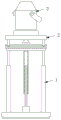
FIG. 1 is a schematic diagram of a laser measuring device for house measurement according to the present utility model;
FIG. 2 is a schematic view of the structure of the elevation adjustment mechanism in the laser measuring apparatus for house measurement according to the present utility model;
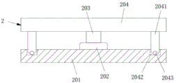
FIG. 3 is a schematic view of the structure of the circumferential adjustment mechanism in the laser measuring device for house measurement according to the present utility model;
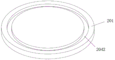
fig. 4 is a schematic structural view of a support base in the laser measuring device for house measurement according to the present utility model.
In the figure:
1. a lifting adjusting mechanism; 2. a circumferential adjustment mechanism; 3. a laser gauge body;
101. a fixed base; 102. a servo motor; 103. a threaded shaft; 104. a thread cylinder; 105. a lifting table;
1051. a limiting telescopic rod;
201. a support base; 202. a rotating electric machine; 203. a support shaft; 204. a rotating seat;
2041. a limit slide bar; 2042. an annular chute; 2043. and limiting the ball.
Detailed Description
The following description of the embodiments of the present utility model will be made clearly and completely with reference to the accompanying drawings, in which it is apparent that the embodiments described are only some embodiments of the present utility model, but not all embodiments. All other embodiments, which can be made by those skilled in the art based on the embodiments of the utility model without making any inventive effort, are intended to be within the scope of the utility model.
As shown in fig. 1 to 4, a laser measuring device for house measurement, comprising:
a lifting adjusting mechanism 1 for adjusting the height of the laser measuring instrument, a circumferential adjusting mechanism 2 for adjusting the angle of the laser measuring instrument and a laser measuring instrument body 3 arranged on the circumferential adjusting mechanism 2;
the lifting adjusting mechanism 1 comprises a fixed base 101, a servo motor 102 is fixedly connected to the center of the top of the fixed base 101, a threaded shaft 103 is fixedly connected to an output shaft of the servo motor 102, a threaded cylinder 104 meshed with the threaded shaft 103 is connected to the threaded shaft 103 in a threaded manner, and a lifting table 105 is fixedly connected to the top of the threaded cylinder 104;
wherein, circumference adjustment mechanism 2 includes fixed connection at the supporting seat 201 at elevating platform 105 top, and the center department fixedly connected with rotating electrical machines 202 at supporting seat 201 top, fixedly connected with back shaft 203 on the output shaft of rotating electrical machines 202, the top fixedly connected with roating seat 204 of back shaft 203, laser measuring instrument body 3 fixed connection is at the top of roating seat 204.
By adopting the technical scheme, the height of the laser measuring device is conveniently adjusted, and the angle of the laser measuring device is conveniently adjusted, so that the use of staff is greatly facilitated, and the practicability of the utility model is improved.
As shown in fig. 1 to 4, the lifting adjustment mechanism 1 further includes an anti-slip placement pad fixedly connected to the bottom of the fixed base 101.
By adopting the above technical scheme, the stability of the fixing base 101 placed on the ground is increased.
As shown in fig. 1-4, the lifting adjustment mechanism 1 further includes two limiting telescopic rods 1051, one end of each limiting telescopic rod 1051 is fixedly connected to the top of the fixed base 101, and the other end of each limiting telescopic rod 1051 is fixedly connected to the bottom of the lifting platform 105.
By adopting the above technical scheme, the stability of the lifting adjustment of the lifting table 105 is increased.
As shown in fig. 1-4, the circumferential adjustment mechanism 2 further includes two limit sliding rods 2041 fixedly connected to two sides of the bottom of the rotating seat 204, an annular sliding groove 2042 matched with the limit sliding rod 2041 is provided at the edge of the top of the supporting seat 201 and corresponding to the position of the limit sliding rod 2041, the bottom of the limit sliding rod 2041 movably penetrates through the annular sliding groove 2042 and extends into the annular sliding groove 2042 to be slidably connected with the inner wall of the annular sliding groove 2042, a limit ball 2043 is further installed at the bottom of the limit sliding rod 2041, and one side of the limit ball 2043, which is close to the annular sliding groove 2042, is in rolling connection with the inner wall of the annular sliding groove 2042;
by adopting the above technical scheme, the stability of rotation adjustment of the rotary seat 204 is increased.
In order to facilitate understanding of the above technical solutions of the present utility model, the following describes in detail the working principle or operation manner of the present utility model in the actual process.
When the laser measuring device for house measurement is used, when the height of the laser measuring instrument body 3 is required to be adjusted, only the servo motor 102 is required to be opened, the servo motor 102 drives the threaded shaft 103 to rotate, and under the action of the threads between the threaded shaft 103 and the threaded cylinder 104, the threaded cylinder 104 is driven to lift and adjust, so that the height of the laser measuring instrument body 3 can be adjusted, when the angle of the laser measuring instrument body 3 is required to be adjusted, only the rotating motor 202 is required to be opened, the rotating motor 202 drives the supporting shaft 203 to rotate, and thus the rotating seat 204 can be driven to rotate circumferentially, and therefore the angle of the laser measuring instrument body 3 can be adjusted, the use of workers is facilitated, and the practicability of the laser measuring instrument is improved.
To sum up: the laser measuring device for house measurement consists of a lifting adjusting mechanism 1, a circumferential adjusting mechanism 2 and a laser measuring instrument body 3, and solves the problems mentioned in the background art.
Although embodiments of the present utility model have been shown and described, it will be understood by those skilled in the art that various changes, modifications, substitutions and alterations can be made therein without departing from the principles and spirit of the utility model, the scope of which is defined in the appended claims and their equivalents.
Claims (7)
1. A laser measurement device for house measurement, comprising:
the laser measuring instrument comprises a lifting adjusting mechanism (1) for adjusting the height of the laser measuring instrument, a circumferential adjusting mechanism (2) for adjusting the angle of the laser measuring instrument and a laser measuring instrument body (3) arranged on the circumferential adjusting mechanism (2);
the lifting adjusting mechanism (1) comprises a fixed base (101), a servo motor (102) is fixedly connected to the center of the top of the fixed base (101), a threaded shaft (103) is fixedly connected to an output shaft of the servo motor (102), a threaded cylinder (104) meshed with the threaded shaft (103) is connected to the threaded shaft (103) in a threaded mode, and a lifting table (105) is fixedly connected to the top of the threaded cylinder (104);
the circumference adjustment mechanism (2) comprises a supporting seat (201) fixedly connected to the top of the lifting table (105), a rotating motor (202) is fixedly connected to the center of the top of the supporting seat (201), a supporting shaft (203) is fixedly connected to an output shaft of the rotating motor (202), a rotating seat (204) is fixedly connected to the top of the supporting shaft (203), and a laser measuring instrument body (3) is fixedly connected to the top of the rotating seat (204).
2. A laser measuring device for house measurement according to claim 1, characterized in that: the lifting adjusting mechanism (1) further comprises an anti-slip placing pad fixedly connected to the bottom of the fixed base (101).
3. A laser measuring device for house measurement according to claim 2, characterized in that: the lifting adjusting mechanism (1) further comprises two limiting telescopic rods (1051), one ends of the limiting telescopic rods (1051) are fixedly connected to the top of the fixed base (101), and the other ends of the limiting telescopic rods (1051) are fixedly connected to the bottom of the lifting table (105).
4. A laser measuring device for house measurement according to claim 3, characterized in that: the circumferential adjusting mechanism (2) further comprises two limiting slide bars (2041) fixedly connected to two sides of the bottom of the rotating seat (204), and an annular sliding groove (2042) matched with the limiting slide bars (2041) is formed in the edge of the top of the supporting seat (201) and corresponds to the limiting slide bars (2041).
5. A laser measuring device for house measurement according to claim 4, characterized in that: the bottom of the limit sliding rod (2041) movably penetrates through the annular sliding groove (2042) and extends into the annular sliding groove (2042) to be connected with the inner wall of the annular sliding groove (2042) in a sliding mode.
6. A laser measuring device for house measurement according to claim 5, characterized in that: and a limiting ball (2043) is further arranged at the bottom of the limiting slide rod (2041).
7. A laser measuring device for house measurement according to claim 6, characterized in that: one side of the limiting ball (2043) close to the annular chute (2042) is in rolling connection with the inner wall of the annular chute (2042).
Priority Applications (1)
| Application Number | Priority Date | Filing Date | Title |
|---|---|---|---|
| CN202223061604.6U CN219121400U (en) | 2022-11-18 | 2022-11-18 | Laser measuring device for house measurement |
Applications Claiming Priority (1)
| Application Number | Priority Date | Filing Date | Title |
|---|---|---|---|
| CN202223061604.6U CN219121400U (en) | 2022-11-18 | 2022-11-18 | Laser measuring device for house measurement |
Publications (1)
| Publication Number | Publication Date |
|---|---|
| CN219121400U true CN219121400U (en) | 2023-06-02 |
Family
ID=86534843
Family Applications (1)
| Application Number | Title | Priority Date | Filing Date |
|---|---|---|---|
| CN202223061604.6U Active CN219121400U (en) | 2022-11-18 | 2022-11-18 | Laser measuring device for house measurement |
Country Status (1)
| Country | Link |
|---|---|
| CN (1) | CN219121400U (en) |
Cited By (1)
| Publication number | Priority date | Publication date | Assignee | Title |
|---|---|---|---|---|
| CN117450392A (en) * | 2023-10-14 | 2024-01-26 | 北京顺鑫天宇建设工程有限公司 | A portable measuring device for civil construction |
-
2022
- 2022-11-18 CN CN202223061604.6U patent/CN219121400U/en active Active
Cited By (1)
| Publication number | Priority date | Publication date | Assignee | Title |
|---|---|---|---|---|
| CN117450392A (en) * | 2023-10-14 | 2024-01-26 | 北京顺鑫天宇建设工程有限公司 | A portable measuring device for civil construction |
Similar Documents
| Publication | Publication Date | Title |
|---|---|---|
| CN207132827U (en) | A kind of bearing roller detection means | |
| CN206515166U (en) | Electronic tetrad strain controlling formula direct shear apparatus | |
| CN208139990U (en) | A kind of base wall thickness detection device for plastic bottle blank | |
| CN209445970U (en) | Tool dimension measuring device | |
| CN213455480U (en) | Optical measurement device for different sizes | |
| CN206740134U (en) | A kind of construction costs measuring scale | |
| CN209147957U (en) | A kind of three-coordinates measuring machine | |
| CN215114431U (en) | Cylindricity detection tool for sleeve parts | |
| CN215846052U (en) | Furniture processing is with airing and putting frame | |
| CN212620670U (en) | an electric power meter | |
| CN221238263U (en) | Hole site detection device and gauge | |
| CN217738183U (en) | Laser thickness gauge with high working efficiency and strong stability | |
| CN207556490U (en) | A kind of intelligent gear engagement measuring instrument of novel automatic | |
| CN206311088U (en) | A kind of thrust articulated bearing assembles height measuring device | |
| CN210089663U (en) | Turbocharger contour detection device | |
| CN215725745U (en) | Terrazzo plate deformation measuring device | |
| CN211904017U (en) | A measuring device for forest planting tree pits | |
| CN213812305U (en) | Measuring instrument for land resource management | |
| CN222166020U (en) | A diameter measuring tool for automobile parts | |
| CN213363729U (en) | Detection device for form and position tolerance of frame structure | |
| CN212300299U (en) | Gauge measuring device with marking function for subway construction | |
| CN206974300U (en) | A kind of helix high precision measuring device | |
| CN214200073U (en) | Measuring device for building engineering technology | |
| CN221018973U (en) | High-precision hob group for gear hobbing machine | |
| CN221006219U (en) | Laser tracking and positioning device of articulated arm measuring machine |
Legal Events
| Date | Code | Title | Description |
|---|---|---|---|
| GR01 | Patent grant | ||
| GR01 | Patent grant |