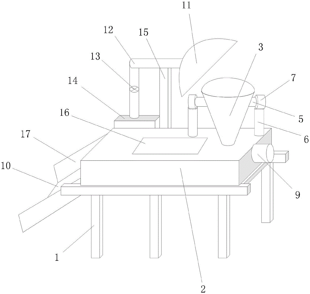
Mixing arrangement is smashed with fodder to ox breed
Technical Field
The application relates to a livestock-raising field especially relates to a mixing arrangement is smashed with fodder to ox breed.
Background
With the progress of society, the living standard of people is continuously improved, the dietary structure of the people is continuously changed, the increase of the demand of meat objectively stimulates the development of large-scale cultivation, the cultivation industry is more and more developed, and the demand of the meat on feed is also more and more high.
In the ox field of breeding, in order to improve the quality of ox, need add multiple nutrient substance in the fodder that uses, still need mix the fodder of multiple different kind and feed, require the fodder to reach certain mixed degree of consistency, and probably need add a certain amount of moisture, this just needs to use the compounding device.
However, the existing mixing devices mostly only have the mixing function, and when the mixing device is used in practice, after corresponding feed is crushed by the corresponding crushing device, the feed is transferred to the mixing device for mixing, so that the mixing efficiency of the feed is low, the cost is high, and the dust generated in the mixing process cannot be treated, thereby affecting the physical and mental health of the working environment and operators.
SUMMERY OF THE UTILITY MODEL
The application provides a mixing arrangement is smashed with fodder to ox breed has solved traditional compounding device function singleness among the prior art, and the fodder compounding is efficient, with high costs and can't carry out the problem handled to the dust that the compounding in-process produced.
For solving above-mentioned technical problem, the application provides a mixing arrangement is smashed to fodder for cattle breeding, includes:
the device comprises a supporting frame, wherein a mixing box with a hollow structure is arranged on the supporting frame, one end of the mixing box is communicated with an inlet pipe, two reamer crushing rollers with opposite directions are arranged in the inlet pipe, a rotating shaft is fixed on the two reamer crushing rollers and penetrates through the inlet pipe and extends to the outer side of the inlet pipe, two support rods are arranged at the position of the mixing box close to the inlet pipe, the upper ends of the two support rods are respectively fixed with a first motor, the output shaft of the first motor is fixedly connected with the outer end of the rotating shaft, a spiral auger is arranged in the mixing box and is driven by a second motor fixed at one side of the mixing box, a discharge plate communicated with the inner cavity of the mixing box is arranged at one side of the mixing box far away from the second motor, and a baffle plate is clamped at the contact position of the discharge plate and the mixing box, the utility model discloses a dust removal device, including inlet pipe, dust removal cover, fan intercommunication, dust collection box, mixing box, bracing piece, dust collection pipe, dust collection box, dust removal cover, dust collection box, mixing box, dust collection pipe, and dust collection pipe, and dust collection pipe, are close to.
Preferably, a transparent cover body is detachably mounted on the mixing box.
Preferably, the support frame includes vertical support rod and horizontal support rod, the horizontal support rod is fixed in the upper end of vertical support rod with one side, be fixed with the connecting rod between the horizontal support rod.
Preferably, the method further comprises the following steps:
and the brake universal wheel is arranged at the bottom of the vertical supporting rod.
Preferably, baffles are further arranged on two sides of the discharging plate.
Compared with the prior art, the feed crushing and mixing device for cattle breeding comprises a support frame, a mixing box with a hollow structure is arranged on the support frame, one end of the mixing box is communicated with a feed pipe, two reamer crushing rollers with opposite directions are arranged in the feed pipe, rotating shafts are fixed on the two reamer crushing rollers, the rotating shafts penetrate through the feed pipe and extend to the outer side of the feed pipe, two support rods are arranged at positions of the mixing box close to the feed pipe, a first motor is respectively fixed at the upper ends of the two support rods, an output shaft of the first motor is fixedly connected with the outer end of the rotating shaft, a spiral auger is arranged in the mixing box, the spiral auger is driven by a second motor fixed at one side of the mixing box, a discharge plate communicated with an inner cavity of the mixing box is arranged at one side of the mixing box far away from the second motor, and a baffle plate is clamped at the contact position of the, the top one side of inlet pipe is provided with the dust excluding hood, and the intercommunication has the dust removal pipe on the dust excluding hood, and the dust removal pipe has dust collecting box through the fan intercommunication, and dust collecting box demountable installation is in one side of compounding case, and one side that the compounding case is close to the inlet pipe is provided with the bracing piece, the upper end and the dust removal pipe fixed connection of bracing piece.
Therefore, when the device is used in practice, the baffle plate is firstly clamped at the contact position of the discharge plate and the mixing box, namely the discharge opening of the mixing box, the reamer crushing roller can be driven to rotate by starting the first motor, different types of feed coming from the inlet pipe is crushed, the generated dust can be sucked into the dust collecting box along the dust collecting pipe by combining the fan and the dust hood while powder is mixed, the dust in the feed is absorbed, the crushed feed can flow into the mixing box, the second motor is simultaneously started, the feed in the mixing box is uniformly mixed by driving the spiral auger to rotate forward or reversely by the second motor, after a period of mixing, the baffle plate is opened, the uniformly mixed feed is output by the rotation of the spiral auger through the baffle plate, and the functional diversity and the mixing efficiency of the mixing device can be improved, the cost is reduced.
Drawings
In order to more clearly explain the technical solution of the present application, the drawings needed to be used in the embodiments are briefly described below, and it is obvious to those skilled in the art that other drawings can be obtained according to the drawings without making any inventive changes.
Fig. 1 is a schematic structural view of a cattle breeding feed crushing and mixing device provided by an embodiment of the present invention;
fig. 2 is a schematic view of the inside of a feeding pipe according to an embodiment of the present invention;
fig. 3 is a schematic view of the interior of a mixing box according to an embodiment of the present invention;
fig. 4 is a schematic view of a supporting frame according to an embodiment of the present invention;
in the figure, 1 supporting frame, 01 vertical supporting rod, 02 horizontal supporting rod, 03 connecting rod, 2 mixing box, 3 feeding pipe, 4 reamer crushing rollers, 5 rotating shaft, 6 supporting rod, 7 first motor, 8 spiral auger, 9 second motor, 10 discharging plate, 11 dust hood, 12 dust removing pipe, 13 fan, 14 dust collecting box, 15 supporting rod, 16 transparent cover body and 17 baffle.
Detailed Description
In order to make those skilled in the art better understand the technical solutions in the present application, the technical solutions in the embodiments of the present application will be described clearly and completely with reference to the accompanying drawings.
The core of this application is to provide a mixing arrangement is smashed to fodder for cattle breeding, can solve traditional compounding device function singleness among the prior art, fodder compounding is efficient, with high costs and can't carry out the problem handled to the dust that the compounding in-process produced.
Fig. 1 is the embodiment of the utility model provides a cattle is bred and uses fodder crushing and mixing device schematic structure, fig. 2 is the embodiment of the utility model provides an inside schematic view of inlet pipe, fig. 3 is the embodiment of the utility model provides an inside schematic view of mixing box, fig. 4 is the embodiment of the utility model provides a support frame structure schematic view that provides, as shown in fig. 1 to fig. 4, include:
a support frame 1, a mixing box 2 with a hollow structure is arranged on the support frame 1, one end of the mixing box 2 is communicated with a feeding pipe 3, two reamer crushing rollers 4 with opposite directions are arranged in the feeding pipe 3, a rotating shaft 5 is fixed on the two reamer crushing rollers 4, the rotating shaft 5 penetrates through the feeding pipe 3 and extends to the outer side of the feeding pipe 3, two support rods 6 are arranged at the position of the mixing box 2 close to the feeding pipe 3, a first motor 7 is respectively fixed at the upper end of each support rod 6, the output shaft of the first motor 7 is fixedly connected with the outer end of the rotating shaft 5, a spiral auger 8 is arranged in the mixing box 2, the spiral auger 8 is driven by a second motor 9 fixed at one side of the mixing box 2, a discharge plate 10 communicated with the inner cavity of the mixing box 2 is arranged at one side of the mixing box 2 far away from the second motor 9, a baffle plate is clamped at the contact position of the discharge plate 10 and the mixing box 2, a dust removing cover 11 is arranged at one side above the feeding pipe 3, the dust hood 11 is communicated with a dust removal pipe 12, the dust removal pipe 12 is communicated with a dust collection box 14 through a fan 13, the dust collection box 14 is detachably mounted on one side of the mixing box 2, a support rod 15 is arranged on one side of the mixing box 2 close to the feeding pipe 3, and the upper end of the support rod 15 is fixedly connected with the dust removal pipe 12.
Specifically, support frame 1 includes vertical support rod 01 and horizontal support rod 02, and horizontal support rod 02 is fixed in the upper end of vertical support rod 01 with one side, is fixed with connecting rod 03 between the horizontal support rod 02, and mixing box 2 is fixed to be set up on horizontal support rod 02 and connecting rod 03, and mixing box 2 is hollow structure, and mixing box 2's structure and size can be confirmed according to actual conditions. The lower extreme of inlet pipe 3 and the inner chamber intercommunication setting of mixing box 2, be provided with two opposite direction's reamer crushing roller 4 in inlet pipe 3, can improve fodder crushing efficiency, two reamer crushing roller 4 are through the output shaft fixed connection of pivot 5 with first motor 7, the one end and the reamer crushing roller 4 of pivot 5 are connected, the other end of pivot 5 runs through inlet pipe 3 and extends to the outside of inlet pipe 3 and with the output shaft fixed connection of first motor 7, first motor 7 is fixed in the upper end of branch 6, branch 6 is fixed to be set up at mixing box 2 and is close to the position department of inlet pipe 3, support first motor 7 through branch 6.
The dust excluding hood 11 sets up in the top one side position department of inlet pipe 3, and the dust excluding hood 11 is through dust removal pipe 12, and dust removal pipe 12 communicates with fan 13 and dust collecting box 14, and dust collecting box 14 demountable installation is in one side of compounding case 2, and dust excluding hood 11 carries out fixed stay through the bracing piece 15 with dust removal pipe 12 fixed connection. In actual use, the dust generated in the feed crushing process can be collected and treated through the cooperation of the dust hood 11, the dust removal pipe 12, the fan 13 and the dust collection box 14, and the dust in the feed is absorbed and treated. Spiral auger 8 is installed in mixing box 2, spiral auger 8 drives through the second motor 9 that is fixed in mixing box 2 one side, when in actual use, corotation and the reversal of mode control spiral auger 8 that can be through operation second motor 9, and then realize all handling mixing of fodder in mixing box 2, mix after all, control spiral auger 8 rotates along same direction, carry the mixed fodder to mixing box 2's discharge gate department, make the mixed fodder in mixing box 2 along the output of play flitch 10 through the striker plate of opening mixing box 2 discharge gate department, the striker plate is not drawn in the picture, the setting of striker plate needs to be accurate along the output of play flitch 10 with the mixed fodder that does not influence in mixing box 2.
In order to facilitate observation of the conditions inside the mixing box 2 and maintenance of the screw auger 8, a transparent cover 16 is preferably detachably mounted on the mixing box 2. In order to improve the moving convenience of the device, it is preferable that the device further comprises: and the brake universal wheel is arranged at the bottom of the vertical supporting rod 01 and is not shown in the figure. In order to prevent the fodder from falling from both sides of the discharging plate 10, it is preferable that baffles 17 are further provided at both sides of the discharging plate 10.
The utility model provides a cattle breeding is with fodder mixing arrangement that smashes, when in actual use, the striker plate joint is in the contact position department of play flitch and mixing box earlier, namely the discharge gate department of mixing box, can drive the rotation of reamer crushing roller through the mode that starts first motor, carry out shredding from the different types of fodder that the inlet pipe came in, can be through the combination of fan and dust excluding hood in the dust collecting box is inhaled the dust along the dust removal pipe in the powder, realize the absorption processing to the dust in the fodder, the fodder after shredding can flow into mixing box, start the second motor simultaneously, carry out the mixing and evenly processing to the fodder in the mixing box through the mode that the second motor drives spiral auger forward rotation or reverse rotation, after a period of compounding, open the striker plate, the fodder of will mixing and evenly passes through the striker plate through the rotation of spiral auger and exports, the functional diversity and the compounding efficiency of compounding device can be improved, reduce cost.
Other embodiments of the present application will be apparent to those skilled in the art from consideration of the specification and practice of the application disclosed herein. This application is intended to cover any variations, uses, or adaptations of the invention following, in general, the principles of the application and including such departures from the present disclosure as come within known or customary practice in the art to which the invention pertains. It is intended that the specification and examples be considered as exemplary only, with a true scope of the disclosure being indicated by the following claims.
It will be understood that the present application is not limited to the precise arrangements described above and shown in the drawings and that various modifications and changes may be made without departing from the scope thereof. The above-described embodiments of the present application do not limit the scope of the present application.