CN214124502U - Protection device for power supply machine network of plant area - Google Patents
Protection device for power supply machine network of plant area Download PDFInfo
- Publication number
- CN214124502U CN214124502U CN202023149650.2U CN202023149650U CN214124502U CN 214124502 U CN214124502 U CN 214124502U CN 202023149650 U CN202023149650 U CN 202023149650U CN 214124502 U CN214124502 U CN 214124502U
- Authority
- CN
- China
- Prior art keywords
- box
- heat dissipation
- box body
- power supply
- protection device
- Prior art date
- Legal status (The legal status is an assumption and is not a legal conclusion. Google has not performed a legal analysis and makes no representation as to the accuracy of the status listed.)
- Active
Links
Images


Abstract
The utility model discloses a factory power supply machine net protection device, the power distribution box comprises a box body, the top of box is open structure, the top of box is equipped with carries out the confined heat dissipation case to this open structure, exhaust grid has been seted up on the lateral wall of heat dissipation case, the bottom of heat dissipation case is equipped with radiator fan, be equipped with the screw thread seat on the lateral wall of heat dissipation case, be equipped with vertical arrangement's screw rod on the inside wall of box, be equipped with the rotatory driving motor of drive screw rod on the inside wall of box, be equipped with heat dissipation grid on the lateral wall of box, the below of box is equipped with the bottom plate, be equipped with the bradyseism subassembly between bottom plate and the box. Has the advantages that: adopt the heat dissipation case of liftable formula structure, cooperation radiator fan drives outside air current and circulates to take away the heat of box inside, in order to ensure power equipment at the inside operational environment of box, avoid the box overheated and cause the trouble, promoted the stability of electric power system during operation.
Description
Technical Field
The utility model relates to a power equipment technical field, concretely relates to factory power supply machine net protection device.
Background
The utility model discloses a coke dry quenching waste heat steam turbine power generation takes the power plant area load and the power supply mode of outer net operation is the common mode of present domestic coke-oven plant, in order to guarantee electric power system's job stabilization, need utilize specific device to protect the circuit, adopt the block terminal as protective equipment usually, because the heat that power equipment produced at the during operation receives the influence of real-time load, when the power supply volume is big, power equipment's consumption is higher, make the inside temperature of block terminal show and rise, and then make power equipment overheated to cause the trouble, and the structure of current block terminal is comparatively simple, and the heat-sinking capability is not enough, can't make timely adjustment according to the inside temperature of block terminal, and then influence power equipment's operating condition, probably can make the device break down when serious, cause economic loss.
Disclosure of Invention
The utility model aims at providing a factory power supply machine net protection device just lies in solving above-mentioned problem to the structure of the block terminal of solving among the prior art is comparatively simple, and the heat-sinking capability is not enough, can't make timely adjustment according to the inside temperature of block terminal, and then influences power equipment's operating condition, probably can make the device break down when serious, causes economic loss's technical problem. The utility model provides an adopt the heat dissipation case of liftable formula structure among the preferred technical scheme among a great deal of technical scheme, cooperation radiator fan drives outside air current and circulates to take away the heat of box inside, in order to ensure power equipment at the inside operational environment of box, avoid the box overheated and cause the trouble, promoted the stable technological effect of electric power system during operation, see the explanation below for details.
In order to achieve the above purpose, the utility model provides a following technical scheme:
the utility model provides a factory power supply machine net protection device, the power distribution box comprises a box body, the top of box is open structure, the top of box is equipped with carries out the confined heat dissipation case to this open structure, exhaust grid has been seted up on the lateral wall of heat dissipation case, the bottom of heat dissipation case is equipped with radiator fan, be equipped with the screw thread seat on the lateral wall of heat dissipation case, be equipped with vertical arrangement's screw rod on the inside wall of box, the screw thread seat passes through the screw thread and installs on the screw rod, be equipped with the rotatory driving motor of drive screw rod on the inside wall of box, be equipped with the heat dissipation grid on the lateral wall of box, the below of box is equipped with the bottom plate, be equipped with the bradyseism subassembly between bottom plate and the box.
Preferably, the cushioning component comprises an outer protective sleeve, an inner sleeve is arranged inside the outer protective sleeve, and a cushioning spring is sleeved between the inner sleeve and the outer protective sleeve.
Preferably, a limiting cylinder is arranged inside the inner sleeve, a damping rod is arranged inside the limiting cylinder, and two ends of the damping rod are respectively abutted to the inner top wall of the outer protective sleeve and the inner bottom surface of the inner sleeve.
Preferably, a layering partition plate is arranged in the box body.
Preferably, a temperature detector is arranged inside the layered partition board.
Preferably, the inner wall of the box body is provided with vertically arranged adjusting holes, and the inside of each adjusting hole is provided with a bearing block for supporting the layered partition plate.
Preferably, the outer side of the box body is provided with an opening and closing door, the opening and closing door is provided with an observation window, and the outer wall of the opening and closing door is provided with a handle.
Preferably, a rain shield is arranged at the top of the heat dissipation box.
Preferably, a sealing ring is arranged on the inner wall of the top opening of the box body.
Has the advantages that: adopt the heat dissipation case of liftable formula structure, cooperation radiator fan drives outside air current and circulates to take away the heat of box inside, in order to ensure power equipment at the inside operational environment of box, avoid the box overheated and cause the trouble, promoted the stability of electric power system during operation.
Drawings
In order to more clearly illustrate the embodiments of the present invention or the technical solutions in the prior art, the drawings used in the description of the embodiments or the prior art will be briefly described below, it is obvious that the drawings in the following description are only some embodiments of the present invention, and for those skilled in the art, other drawings can be obtained according to these drawings without creative efforts.
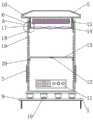
Fig. 1 is a front view of the present invention;
fig. 2 is a front sectional view of the present invention;
fig. 3 is an enlarged view of a portion of fig. 2 according to the present invention;
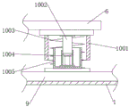
FIG. 4 is a main structural view of the shock absorption assembly of the present invention;
fig. 5 is a side view of the present invention;
fig. 6 is a main structural view of the present invention in an operating state.
The reference numerals are explained below:
1. a non-slip mat; 2. a handle; 3. opening and closing the door; 4. an observation window; 5. a rain shield; 6. a box body; 7. a heat dissipation grid; 8. connecting a hinge; 9. a base plate; 10. a cushioning component; 1001. an outer protective sleeve; 1002. a damping lever; 1003. a cushioning spring; 1004. a limiting cylinder; 1005. an inner sleeve; 11. a line bank; 12. a temperature detector; 13. a dust partition plate; 14. a heat radiation fan; 15. an exhaust grill; 16. a seal ring; 17. a heat dissipation box; 18. a drive motor; 19. an adjustment hole; 20. a bearing block; 21. a screw; 22. a threaded seat; 23. and (4) fixing the ring.
Detailed Description
In order to make the objects, technical solutions and advantages of the present invention clearer, the technical solutions of the present invention will be described in detail below. It is to be understood that the embodiments described are only some embodiments of the invention, and not all embodiments. Based on the embodiments of the present invention, all other embodiments obtained by a person skilled in the art without creative efforts belong to the protection scope of the present invention.
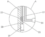
Referring to fig. 1-6, the utility model provides a plant power supply network protection device, including a box body 6, the top of the box body 6 is an open structure, a sealing ring 16 is arranged on the inner wall of the open structure of the box body 6, the outer side edge of a heat dissipation box 17 can be sealed, thereby preventing dust and rainwater in the external environment from entering the inside of the box body 6, and ensuring the working environment of the power equipment to be stable, the top of the box body 6 is provided with the heat dissipation box 17 for sealing the open structure, the side wall of the heat dissipation box 17 is provided with an exhaust grille 15, the number of the heat dissipation grilles 7 is four, the four side walls are respectively arranged on the four side walls of the heat dissipation box 17, the bottom of the heat dissipation box 17 is provided with heat dissipation fans 14, the number of the heat dissipation fans 14 is three, the heat dissipation fans are equidistantly arranged on the bottom surface of the heat dissipation box 17, and can drive the air flow circulation, thereby reducing the temperature inside the box body 6, the outer side wall of the heat dissipation box 17 is provided with the threaded seats 22, the total four threaded seats 22 are respectively arranged at four corners of the heat dissipation box 17, threaded holes for the threaded rods 21 to pass through are formed in the threaded seats 22, the threaded seats can be matched with the threaded rods 21, the threaded rods 21 are vertically arranged on the inner side wall of the box body 6, the threaded seats 22 are installed on the threaded rods 21 through threads, a driving motor 18 for driving the threaded rods 21 to rotate is arranged on the inner side wall of the box body 6, the driving motor 18 works to drive the threaded rods 21 to rotate, fixing rings 23 are arranged on the inner side wall of the box body 6, the positions of the threaded rods 21 can be clamped and fixed, the threaded rods 21 can rotate inside the fixing rings 23, so that the threaded rods 21 are kept stable during rotation, the heat dissipation box 17 is driven to ascend or descend through the threaded fit between the threaded rods 21 and the threaded seats 22, the position of the exhaust grille 15 is convenient to adjust, and facilitate air circulation, be equipped with radiator grille 7 on the lateral wall of box 6, radiator grille 7's the outside is equipped with and is used for waterproof casing, looks UNICOM in radiator grille 7's the inside and the box 6, so that the air current passes through, the below of box 6 is equipped with bottom plate 9, install slipmat 1 on bottom plate 9's the bottom surface, can increase and the factory floor between the frictional force, thereby ensure the stability when box 6 uses, be equipped with bradyseism subassembly 10 between bottom plate 9 and the box 6, bradyseism subassembly 10 can reduce the influence of vibrations to box 6.
The inside of inner skleeve 1005 is equipped with spacing section of thick bamboo 1004, and the inside of spacing section of thick bamboo 1004 is equipped with damping rod 1002, and the both ends of damping rod 1002 butt respectively on the interior roof of outer lag 1001 and on the interior bottom surface of inner skleeve 1005, and damping rod 1002 can stretch out and draw back in spacing section of thick bamboo 1004, and then realizes the bradyseism, and the design that adopts the secondary bradyseism can hoisting device's shock resistance, and then ensures the stability of power equipment during operation.
Be equipped with the layering baffle in the box 6, the layering baffle can be kept apart 6 inside layering of box to installation power equipment.
Inside being equipped with thermodetector 12 of layering baffle, adopting thermodetector 12's design, can detecting the inside temperature of device to in time dispel the heat, in order to avoid power equipment overheated impaired.
Offer vertically arranged's regulation hole 19 on the inner wall of box 6, regulation hole 19 equidistant vertical arrangement is on each lateral wall of box 6 inside, 19 internally mounted of regulation hole has the bearing piece 20 that supports to the layering baffle, can install bearing piece 20 on the inner wall of box 6 through the bolt to be convenient for support the layering baffle, can adjust the position of layering baffle according to the user demand of difference, and then be convenient for install the power equipment of not unidimensional size.
The outside of box 6 is equipped with opening and shutting door 3, and opening and shutting door 3 rotates through connecting hinge 8 to be installed on the outer wall of box 6, is equipped with observation window 4 on the opening and shutting door 3, installs handle 2 on the outer wall of opening and shutting door 3, adopts the design of opening and shutting door 3, can be convenient for operating personnel to overhaul the inside power equipment of box 6 to in time observe the operating condition of the inside power equipment of box 6 through observation window 4.
The top of heat dissipation case 17 is equipped with rain-proof cover 5, and rain-proof cover 5 can carry out the water conservancy diversion to the rainwater, avoids the rainwater to flow into 6 inside power equipment troubles that cause of box.
Be equipped with sealing washer 16 on the open-top's of box 6 inner wall, sealing washer 16 can promote the sealed effect of box 6, avoids inside the rainwater flows into box 6.
By adopting the structure, when in use, the external cable is connected with the wiring bar 11 so as to facilitate the transmission of power signals, related power equipment is installed in the box body 6, the opening and closing door 3 is closed to seal the box body 6, when the power equipment works, the temperature in the box body 6 rises, the heat in the box body 6 is discharged through the heat dissipation grating 7, when the temperature in the box body 6 is overhigh, the temperature detector 12 on the layered partition board gives an alarm, and then the driving motor 18 is controlled to work, so that the driving motor 18 drives the screw rod 21 to rotate, the heat dissipation box 17 is driven to rise through the thread fit between the screw rod 21 and the thread seat 22, the exhaust grating 15 on the side wall of the heat dissipation box 17 is exposed, then the heat dissipation fan 14 works to drive airflow to enter from the heat dissipation grating 7 and then is led out from the heat dissipation grating 7 after the internal ascending circulation of the box body 6 so as to reduce the internal temperature of the box body 6, ensure that the operating condition of the inside power equipment of box 6 remains stable, adopt the heat dissipation case 17 of liftable formula structure, cooperation radiator fan 14 drives outside air current and circulates to take away the inside heat of box 6, in order to ensure power equipment at the inside operational environment of box 6, avoid box 6 overheated and cause the trouble, promoted the stability of electric power system during operation.
The above embodiments are only specific embodiments of the present invention, but the scope of the present invention is not limited thereto, and any person skilled in the art can easily think of changes or substitutions within the technical scope of the present invention, and all should be covered within the scope of the present invention. Therefore, the protection scope of the present invention shall be subject to the protection scope of the claims.
Claims (9)
1. The utility model provides a factory power supply machine net protection device, includes box (6), its characterized in that: the top of the box body (6) is of an open structure, the top of the box body (6) is provided with a heat dissipation box (17) for sealing the open structure, an exhaust grille (15) is arranged on the side wall of the heat dissipation box (17), a heat dissipation fan (14) is arranged at the bottom of the heat dissipation box (17), the outer side wall of the heat dissipation box (17) is provided with a threaded seat (22), the inner side wall of the box body (6) is provided with a vertically arranged screw rod (21), the threaded seat (22) is arranged on the screw rod (21) through threads, a driving motor (18) for driving the screw rod (21) to rotate is arranged on the inner side wall of the box body (6), the outer side wall of the box body (6) is provided with a heat dissipation grid (7), a bottom plate (9) is arranged below the box body (6), and a shock absorption component (10) is arranged between the bottom plate (9) and the box body (6).
2. The plant-based power supply motor network protection device of claim 1, wherein: bradyseism subassembly (10) are including outer lag (1001), outer lag (1001) inside inner skleeve (1005) that is equipped with, the cover is equipped with bradyseism spring (1003) between inner skleeve (1005) and outer lag (1001).
3. The plant-based power supply motor network protection device of claim 2, wherein: a limiting cylinder (1004) is arranged inside the inner sleeve (1005), a damping rod (1002) is arranged inside the limiting cylinder (1004), and two ends of the damping rod (1002) are respectively abutted to the inner top wall of the outer protective sleeve (1001) and the inner bottom surface of the inner sleeve (1005).
4. The plant-based power supply motor network protection device of claim 1, wherein: a layered partition plate (13) is arranged in the box body (6).
5. The plant-based power supply motor network protection device of claim 4, wherein: and a temperature detector (12) is arranged in the layering partition plate (13).
6. The plant-based power supply motor network protection device of claim 4, wherein: the inner wall of the box body (6) is provided with vertically arranged adjusting holes (19), and bearing blocks (20) for supporting the layered partition plates (13) are arranged in the adjusting holes (19).
7. The plant-based power supply motor network protection device of claim 1, wherein: the outer side of the box body (6) is provided with an opening and closing door (3), the opening and closing door (3) is provided with an observation window (4), and the outer wall of the opening and closing door is provided with a handle (2).
8. The plant-based power supply motor network protection device of claim 1, wherein: and a rain shield (5) is arranged at the top of the heat dissipation box (17).
9. The plant-based power supply motor network protection device of claim 1, wherein: and a sealing ring (16) is arranged on the inner wall of the top opening of the box body (6).
Priority Applications (1)
| Application Number | Priority Date | Filing Date | Title |
|---|---|---|---|
| CN202023149650.2U CN214124502U (en) | 2020-12-24 | 2020-12-24 | Protection device for power supply machine network of plant area |
Applications Claiming Priority (1)
| Application Number | Priority Date | Filing Date | Title |
|---|---|---|---|
| CN202023149650.2U CN214124502U (en) | 2020-12-24 | 2020-12-24 | Protection device for power supply machine network of plant area |
Publications (1)
| Publication Number | Publication Date |
|---|---|
| CN214124502U true CN214124502U (en) | 2021-09-03 |
Family
ID=77514108
Family Applications (1)
| Application Number | Title | Priority Date | Filing Date |
|---|---|---|---|
| CN202023149650.2U Active CN214124502U (en) | 2020-12-24 | 2020-12-24 | Protection device for power supply machine network of plant area |
Country Status (1)
| Country | Link |
|---|---|
| CN (1) | CN214124502U (en) |
-
2020
- 2020-12-24 CN CN202023149650.2U patent/CN214124502U/en active Active
Similar Documents
| Publication | Publication Date | Title |
|---|---|---|
| CN103327776A (en) | Waterproof and dustproof structure of outdoor equipment cabinet and outdoor equipment cabinet with waterproof and dustproof structure | |
| CN108843524B (en) | Heat dissipation system for wind generating set and wind generating set | |
| CN206401777U (en) | A kind of power equipment case with heat sinking function | |
| CN213818549U (en) | Frequency converter with good heat dissipation performance | |
| CN106368508A (en) | Power construction self-generating electricity guard fence device | |
| CN214124502U (en) | Protection device for power supply machine network of plant area | |
| CN113257523B (en) | Remote anti-theft special transformer based on Internet of things | |
| CN210430447U (en) | Waterproof distribution box | |
| CN211128616U (en) | Electric automation control's heat dissipation regulator cubicle | |
| CN113451889A (en) | Box-type substation with remote monitoring function | |
| CN210715203U (en) | High temperature and high pressure resistant centrifugal fan | |
| CN111641146A (en) | Electric power high-voltage board with shock attenuation safeguard function | |
| CN214798511U (en) | Workshop is with electrical apparatus switch board from taking heat radiation structure | |
| CN216106297U (en) | Distributed rural sewage treatment system | |
| CN209659825U (en) | A kind of mining electrical control chest with dust reduction capability | |
| CN203340466U (en) | Waterproof dustproof structure for outdoor cabinet, and outdoor cabinet equipped with waterproof dustproof structure | |
| CN210694663U (en) | Automatic control cabinet of hydraulic generator | |
| CN214481666U (en) | Sewage treatment station PLC automatic control cabinet with strong heat radiation structure | |
| CN214177881U (en) | Speed regulation controller for excitation synchronous motor | |
| CN208983723U (en) | A kind of micro electronmechanical refrigerator protective shell | |
| CN215596516U (en) | Electric valve positioner with waterproof function | |
| CN218070610U (en) | Control cabinet for power grid power control system | |
| CN219321914U (en) | Safety protection structure of photovoltaic power station | |
| CN210744480U (en) | Cabinet body sealing mechanism | |
| CN219204335U (en) | Inverter with explosion-proof structure for photovoltaic power station |
Legal Events
| Date | Code | Title | Description |
|---|---|---|---|
| GR01 | Patent grant | ||
| GR01 | Patent grant |