CN214079547U - Cutting device is used in roller production - Google Patents
Cutting device is used in roller production Download PDFInfo
- Publication number
- CN214079547U CN214079547U CN202022815515.0U CN202022815515U CN214079547U CN 214079547 U CN214079547 U CN 214079547U CN 202022815515 U CN202022815515 U CN 202022815515U CN 214079547 U CN214079547 U CN 214079547U
- Authority
- CN
- China
- Prior art keywords
- moving
- seat
- cutting
- clamping plate
- clamping
- Prior art date
- Legal status (The legal status is an assumption and is not a legal conclusion. Google has not performed a legal analysis and makes no representation as to the accuracy of the status listed.)
- Active
Links
Images


Landscapes
- Sawing (AREA)
Abstract
The utility model provides a cutting device for roller production in the technical field of cutting equipment, which comprises a frame, a feeding plate is arranged on the frame, a conveying mechanism, a first clamping mechanism and a second clamping mechanism are arranged on the frame, the conveying mechanism comprises a moving component capable of reciprocating in the left and right direction, the moving component comprises a first moving seat and a second moving seat which are symmetrically arranged, a limiting plate capable of reciprocating on the feeding plate in the front and back direction is arranged on the first moving seat, a cutting groove is arranged on the frame, the first clamping mechanism and the second clamping mechanism are respectively arranged on the frame at the left and right sides of the cutting groove, the first clamping mechanism comprises a first clamping plate and a second clamping plate capable of reciprocating in the front and back direction, the second clamping mechanism comprises a third clamping plate and a fourth clamping plate capable of reciprocating in the front and back direction, a cutting mechanism is also arranged at one side of the frame, the cutting mechanism comprises a fixed seat, a saw seat capable of rotating up and down is hinged on the fixed seat, the saw seat is rotatably connected with a saw blade; the utility model discloses the difficult drunkenness of tubular product, cutting accuracy is high.
Description
Technical Field
The utility model belongs to the technical field of cutting equipment, in particular to cutting device is used in roller production.
Background
The roller is a cylindrical rotatable object in machinery, a common power source (such as a motor) in the machinery drives the roller to drive other materials to advance, or the roller generates pressure to process the materials, the roller is produced by a large amount of pipe materials such as an outer roller pipe and a support shaft, and the pipe materials are required to be cut in the production process of the pipe materials so as to meet the pipe material lengths required by different occasions and models, so that the pipe sawing machine with excellent comprehensive performance has important significance for the production of the roller.
During the tubular product cutting among the prior art is handled, need the workman to realize the fixed of pipe fitting through the mode that both hands pressed usually, this operation mode potential safety hazard, intensity of labour is too big, and work efficiency is still low moreover, carries out mass production in-process, just must hire a large amount of skilled operating personnel of technique, and the cost of labor is high, and adopts the manual saw that cuts, can have artifical positioning accuracy low, the pay-off difficulty, the precision of saw cutting shortcoming such as not low.
SUMMERY OF THE UTILITY MODEL
To the defect among the prior art, the utility model discloses an aim at solves the weak point among the prior art, has solved among the prior art easy drunkenness of tubular product, and cutting accuracy hangs down technical problem provides a cutting device is used in roller production, and this device tubular product is difficult for the drunkenness, and cutting accuracy is high.
The purpose of the utility model is realized like this: a cutting device for roller production comprises a rack, wherein a feeding plate is arranged on the rack, a conveying mechanism, a first clamping mechanism and a second clamping mechanism are sequentially arranged on the rack from left to right, the conveying mechanism comprises a moving assembly capable of moving in the left-right direction in a reciprocating manner, the moving assembly comprises a first moving seat and a second moving seat which are symmetrically arranged, a limiting plate capable of moving in the front-back direction in a reciprocating manner is arranged on the first moving seat, a cutting groove is formed in the rack, the first clamping mechanism and the second clamping mechanism are respectively arranged on the rack on the left side and the right side of the cutting groove, the first clamping mechanism comprises a first clamping plate and a second clamping plate capable of moving in the front-back direction in a reciprocating manner, the first clamping plate and the second clamping plate are oppositely arranged, the second clamping mechanism comprises a third clamping plate and a fourth clamping plate capable of moving in the front-back direction in a reciprocating manner, the third clamping plate and the fourth clamping plate are oppositely arranged, and one side of the rack is further provided with a cutting mechanism, the cutting mechanism comprises a fixed seat, a saw seat capable of rotating up and down is hinged to the fixed seat, a saw blade is rotatably connected to the saw seat, and the saw blade is arranged right above the cutting groove.
The utility model discloses during operation, the tubular product of last level processing unit is carried on the material loading board, the limiting plate moves backward, fix tubular product between limiting plate and removal seat two, then remove seat one and remove seat two and move right simultaneously, when tubular product is moved to the cutting length position of settlement, remove seat one and remove seat two and stop moving, splint two move backward, make tubular product fix between splint one and splint two, splint four move backward, make tubular product fix between splint three and splint four, then the saw bit rotates, the saw seat drives the saw bit and rotates downwards towards the direction of cutting groove, the saw bit cuts tubular product off, realize the cutting of tubular product; compared with the prior art, the beneficial effects of the utility model reside in that: the arrangement of the conveying mechanism in the utility model can stably convey the pipe to the lower part of the saw blade, the operation is stable, and the use is convenient; the first clamping mechanism and the second clamping mechanism are arranged, so that the pipe is firmly fixed when being cut, the cutting movement is avoided, the pipe cutting precision is high, and the cutting effect is good; the utility model discloses can be applied to in the cutting work of tubular product.
In order to realize that the first moving seat and the second moving seat can slide on the rack, a first sliding rail and a second sliding rail are arranged on the front side and the rear side of the feeding plate in parallel, a first sliding groove matched with the first sliding rail is formed in the first moving seat, and a second sliding groove matched with the second sliding rail is formed in the second moving seat.
The saw blade lifting device is characterized in that the saw blade can lift, the saw blade is rotatable, the cutting mechanism further comprises a first linear driver hinged to the rack, the first linear driver is arranged above the fixed seat, a telescopic rod is arranged on the first linear driver, the telescopic rod is hinged to the saw seat, a driving motor is arranged on the saw seat, and an output shaft of the driving motor is connected with the saw blade.
In order to realize that the first moving seat and the second moving seat can linearly move in a reciprocating manner in the left-right direction, the rack on the front side and the rear side of the feeding plate is respectively provided with a fixed plate, the two fixed plates are provided with a linear driver II and a linear driver III, the linear driver II and the linear driver III are respectively provided with a first push rod and a second push rod which can linearly move in a reciprocating manner in the left-right direction, the first push rod is connected with the first moving seat, and the second push rod is connected with the second moving seat.
In order to realize the reciprocating linear movement of the limiting plate in the front-back direction, a linear driver IV is arranged on the moving seat I, a push-pull rod capable of reciprocating linear movement in the front-back direction is arranged on the linear mover IV, and one end, far away from the linear driver IV, of the push-pull rod is connected with the limiting plate.
In order to realize that splint two can be at the reciprocal rectilinear movement of back and forth direction, cut groove one side be equipped with guided way one in the frame, be equipped with sharp driver five in the frame of guided way one top, be equipped with the carriage release lever one that can be in back and forth direction reciprocating motion on the sharp driver five, the one end that linear driver five was kept away from to carriage release lever is connected on splint two, be equipped with on splint two with guided way matched with guided way one.
In order to realize that splint four can be at the reciprocal rectilinear movement of back and forth direction, cut the cut groove opposite side be equipped with guided way two in the frame, be equipped with sharp driver six in the frame of guided way two top, be equipped with the carriage release lever two that can be in back and forth direction reciprocating motion on the sharp driver six, the one end that linear driver six was kept away from to carriage release lever two is connected on splint four, be equipped with on splint four with guided way one matched with guided way two.
Drawings
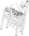
Fig. 1 is a front view of the present invention.
Fig. 2 is a first perspective view of the present invention.
Fig. 3 is a partially enlarged view of a portion a in fig. 2.
Fig. 4 is a second perspective view of the present invention.
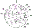
Fig. 5 is a partially enlarged view of B in fig. 4.
In the figure: 1 rack, 101 feeding plate, 102 cutting groove, 103 sliding rail one, 104 sliding rail two, 105 guiding rail one, 106 guiding rail two, 2 conveying mechanism, 201 moving assembly, 201a moving seat one, 201b sliding groove one, 201c moving seat two, 201d sliding groove two, 202 limiting plate, 203 fixing plate, 204 linear driver two, 204a push rod one, 205 linear driver three, 205a push rod two, 206 linear driver four, 206a push-pull rod, 3 clamping mechanism one, 301 clamping plate one, 302 clamping plate two, 303 guiding groove one, 304 linear driver five, 305 moving rod one, 4 clamping mechanism two, 401 clamping plate three, 402 clamping plate four, 403 guiding groove two, 404 linear driver six, 405 moving rod two, 5 cutting mechanism, 501 fixing seat, 502 saw seat, 503 saw blade, 504 linear driver one, 505, 506 driving motor.
Detailed Description
The present invention will be further described with reference to the accompanying drawings.
As shown in fig. 1 to 5, a cutting device for roller production comprises a frame 1, a feeding plate 101 is arranged on the frame 1, a conveying mechanism 2, a first clamping mechanism 3 and a second clamping mechanism 4 are sequentially arranged on the frame 1 from left to right, the conveying mechanism 2 comprises a moving assembly 201 capable of reciprocating in the left-right direction, the moving assembly 201 comprises a first moving seat 201a and a second moving seat 201c which are symmetrically arranged, a limiting plate 202 capable of reciprocating on the feeding plate 101 in the front-back direction is arranged on the first moving seat 201a, a cutting groove 102 is arranged on the frame 1, the first clamping mechanism 3 and the second clamping mechanism 4 are respectively arranged on the frame 1 at the left side and the right side of the cutting groove 102, the first clamping mechanism 3 comprises a first clamping plate 301 and a second clamping plate 302 capable of reciprocating in the front-back direction, the first clamping plate 301 is arranged opposite to the second clamping plate 302, the second clamping mechanism 4 comprises a third clamping plate 401 and a fourth clamping plate 402 capable of reciprocating in the front-back direction, the third clamping plate 401 and the fourth clamping plate 402 are arranged oppositely, one side of the rack 1 is also provided with a cutting mechanism 5, the cutting mechanism 5 comprises a fixed seat 501, a saw seat 502 capable of rotating up and down is hinged on the fixed seat 501, a saw blade 503 is rotatably connected on the saw seat 502, and the saw blade 503 is right above the cutting groove 102; a first sliding rail 103 and a second sliding rail 104 are arranged on the front side and the rear side of the feeding plate 101 in parallel, a first sliding groove 201b matched with the first sliding rail 103 is formed in the first moving seat 201a, and a second sliding groove 201d matched with the second sliding rail 104 is formed in the second moving seat 201 c; the cutting mechanism 5 further comprises a first linear driver 504 hinged on the rack 1, the first linear driver 504 is arranged above the fixed seat 501, a telescopic rod 505 is arranged on the first linear driver 504, the telescopic rod 505 is hinged with the saw seat 502, a driving motor 506 is arranged on the saw seat 502, and an output shaft of the driving motor 506 is connected with the saw blade 503; the fixed plates 203 are respectively arranged on the machine frame 1 on the front side and the rear side of the feeding plate 101, the two fixed plates 203 are respectively provided with a linear driver II 204 and a linear driver III 205, the linear driver II 204 and the linear driver III 205 are respectively provided with a push rod I204 a and a push rod II 205a which can reciprocate linearly in the left-right direction, the push rod I204 a is connected with the moving seat I201 a, and the push rod II 205a is connected with the moving seat II 201 c; a linear driver IV 206 is arranged on the first moving seat 201a, a push-pull rod 206a capable of moving linearly back and forth is arranged on the linear mover IV, and one end, far away from the linear driver IV 206, of the push-pull rod 206a is connected with the limiting plate 202; a first guide rail 105 is arranged on the rack 1 on one side of the cutting groove 102, a fifth linear driver 304 is arranged on the rack 1 above the first guide rail 105, a first moving rod 305 capable of reciprocating in the front-back direction is arranged on the fifth linear driver 304, one end, far away from the fifth linear driver 304, of the first moving rod 305 is connected to a second clamping plate 302, and a first guide groove 303 matched with the first guide rail 105 is arranged on the second clamping plate 302; a second guide rail 106 is arranged on the rack 1 on the other side of the cutting groove 102, a sixth linear driver 404 is arranged on the rack 1 above the second guide rail 106, a second moving rod 405 capable of reciprocating in the front-back direction is arranged on the sixth linear driver 404, one end, far away from the sixth linear driver 404, of the second moving rod 405 is connected to a fourth clamping plate 402, and a second guide groove 403 matched with the first guide rail 105 is arranged on the fourth clamping plate 402.
When the utility model works, the pipe of the upper stage processing unit is conveyed to the feeding plate 101, the push-pull rod 206a of the linear pneumatic actuator IV moves backwards, the push-pull rod 206a pushes the limit plate 202 to move backwards, the pipe is fixed between the limit plate 202 and the second moving seat 201c, then the push rod one 204a of the linear actuator II 204 and the push rod two 205a of the linear actuator III 205 move rightwards simultaneously, the push rod one 204a pushes the first moving seat 201a to move rightwards along the slide rail one 103, the push rod two 205a pushes the second moving seat 201c to move rightwards along the slide rail two 104, namely, the first moving seat 201a and the second moving seat 201c move rightwards simultaneously, the pipe is driven to move rightwards, when the pipe is moved to the set cutting length position, the linear actuator II 204 and the linear actuator III 205 stop moving simultaneously, the moving rod one 305 of the linear actuator V304 moves backwards, the moving rod one 305 pushes the clamp plate II 302 to move backwards along the guide rail I105, the pipe is fixed between the first clamping plate 301 and the second clamping plate 302, the second moving rod 405 of the sixth linear driver 404 moves backwards, the second moving rod 405 pushes the fourth clamping plate 402 to move backwards along the second guide rail 106, so that the pipe is fixed between the third clamping plate 401 and the fourth clamping plate 402, then the driving motor 506 drives the saw blade 503 to rotate, the telescopic rod 505 of the first linear driver 504 extends out, the telescopic rod 505 pushes the saw base 502 to rotate downwards, the saw base 502 drives the saw blade 503 to rotate downwards towards the direction of the cutting groove 102, the saw blade 503 cuts the pipe, and the like, so that the pipe is cut; compared with the prior art, the beneficial effects of the utility model reside in that: the arrangement of the conveying mechanism 2 in the utility model can stably convey the pipe to the lower part of the saw blade 503, the operation is stable, and the use is convenient; the first clamping mechanism 3 and the second clamping mechanism 4 are arranged, so that the pipe is firmly fixed when being cut, the cutting movement is avoided, the pipe cutting precision is high, and the cutting effect is good; the utility model discloses can be applied to in the cutting work of tubular product.
The present invention is not limited to the above embodiments, and based on the technical solutions disclosed in the present invention, those skilled in the art can make some replacements and transformations for some technical features without creative labor according to the disclosed technical contents, and these replacements and transformations are all within the protection scope of the present invention.
Claims (7)
1. A cutting device for roller production comprises a rack and is characterized in that a feeding plate is arranged on the rack, a conveying mechanism, a first clamping mechanism and a second clamping mechanism are sequentially arranged on the rack from left to right, the conveying mechanism comprises a moving assembly capable of moving in a left-right direction in a reciprocating manner, the moving assembly comprises a first moving seat and a second moving seat which are symmetrically arranged, a limiting plate capable of moving in a front-back direction on the feeding plate is arranged on the first moving seat, a cutting groove is formed in the rack, the first clamping mechanism and the second clamping mechanism are respectively arranged on the rack on the left side and the right side of the cutting groove, the first clamping mechanism comprises a first clamping plate and a second clamping plate capable of moving in a front-back direction in a reciprocating manner, the first clamping plate and the second clamping plate are oppositely arranged, the second clamping mechanism comprises a third clamping plate and a fourth clamping plate capable of moving in a front-back direction in a reciprocating manner, and the third clamping plate and the fourth clamping plate are oppositely arranged, one side of frame still is equipped with cutting mechanism, cutting mechanism includes the fixing base, it has saw seat that can the tilting to articulate on the fixing base, the last rotatable saw bit that is connected with of saw seat, the saw bit is directly over cutting cut groove.
2. The cutting device for roller production according to claim 1, wherein a first sliding rail and a second sliding rail are arranged in parallel on the front side and the rear side of the feeding plate, the first sliding groove matched with the first sliding rail is arranged on the first moving seat, and the second sliding groove matched with the second sliding rail is arranged on the second moving seat.
3. The cutting device for roller production according to claim 1, wherein the cutting mechanism further comprises a first linear driver hinged to the frame, the first linear driver is arranged above the fixed seat, a telescopic rod is arranged on the first linear driver, the telescopic rod is hinged to a saw seat, a driving motor is arranged on the saw seat, and an output shaft of the driving motor is connected with the saw blade.
4. The cutting device for producing the roller as claimed in claim 2, wherein the frame on the front and rear sides of the feeding plate is respectively provided with a fixing plate, two fixing plates are provided with a second linear actuator and a third linear actuator, the second linear actuator and the third linear actuator are respectively provided with a first push rod and a second push rod which can reciprocate linearly in the left-right direction, the first push rod is connected with the first moving seat, and the second push rod is connected with the second moving seat.
5. The cutting device for roller production as claimed in claim 4, wherein the first moving seat is provided with a linear actuator IV, the linear mover IV is provided with a push-pull rod capable of moving linearly back and forth, and one end of the push-pull rod, which is far away from the linear actuator IV, is connected to the limiting plate.
6. The cutting device for producing the roller according to claim 5, wherein a first guide rail is arranged on the rack on one side of the cutting groove, a fifth linear driver is arranged on the rack above the first guide rail, a first moving rod capable of reciprocating in the front-back direction is arranged on the fifth linear driver, one end of the first moving rod, far away from the fifth linear driver, is connected to a second clamping plate, and a first guide groove matched with the first guide rail is arranged on the second clamping plate.
7. The cutting device for roller production according to any one of claims 1 to 6, wherein a second guide rail is arranged on the frame on the other side of the cutting groove, a sixth linear driver is arranged on the frame above the second guide rail, a second moving rod capable of reciprocating in the front-back direction is arranged on the sixth linear driver, one end of the second moving rod, far away from the sixth linear driver, is connected to a fourth clamping plate, and a second guide groove matched with the first guide rail is arranged on the fourth clamping plate.
Priority Applications (1)
| Application Number | Priority Date | Filing Date | Title |
|---|---|---|---|
| CN202022815515.0U CN214079547U (en) | 2020-11-30 | 2020-11-30 | Cutting device is used in roller production |
Applications Claiming Priority (1)
| Application Number | Priority Date | Filing Date | Title |
|---|---|---|---|
| CN202022815515.0U CN214079547U (en) | 2020-11-30 | 2020-11-30 | Cutting device is used in roller production |
Publications (1)
| Publication Number | Publication Date |
|---|---|
| CN214079547U true CN214079547U (en) | 2021-08-31 |
Family
ID=77453729
Family Applications (1)
| Application Number | Title | Priority Date | Filing Date |
|---|---|---|---|
| CN202022815515.0U Active CN214079547U (en) | 2020-11-30 | 2020-11-30 | Cutting device is used in roller production |
Country Status (1)
| Country | Link |
|---|---|
| CN (1) | CN214079547U (en) |
-
2020
- 2020-11-30 CN CN202022815515.0U patent/CN214079547U/en active Active
Similar Documents
| Publication | Publication Date | Title |
|---|---|---|
| CN105397849A (en) | Sugarcane seed-taking, conveying and cutting device | |
| CN208712716U (en) | A kind of long U tube bending machine | |
| CN214079547U (en) | Cutting device is used in roller production | |
| CN212918113U (en) | High-precision automatic laser cutting equipment for special-shaped pipes | |
| CN213197932U (en) | Woodworking sawing machine for processing raw wood | |
| CN113441602A (en) | Workpiece edge cutting device | |
| CN213888450U (en) | Efficient tube sawing device for roller production | |
| CN214185537U (en) | Cutting device is used in production of high accuracy roller | |
| CN201076973Y (en) | Multi-head laser cutting machine tool | |
| CN217370663U (en) | Pipe cutting device for machining | |
| CN213499149U (en) | High-precision tube sawing device for roller production | |
| CN213380233U (en) | Portable long material chamfering device | |
| CN213504756U (en) | Roller production is with pipe cutting device of convenient unloading | |
| CN112677258B (en) | Continuous lengthening and sizing saw cutting device and method for strip wood | |
| CN210587451U (en) | Grooving device for large-sized component | |
| CN204094966U (en) | A kind of ceramic member cutter sweep | |
| CN213496894U (en) | Tube sawing machine for roller production | |
| CN216126634U (en) | Automatic cutting machine | |
| CN111283807A (en) | Numerical control flower mud cutting machine | |
| CN213496893U (en) | Automatic feeding cutting machine is used in roller production | |
| CN207577294U (en) | Double-layered movable material platform | |
| CN213504552U (en) | Material feeding unit is used in roller production | |
| CN220362057U (en) | Fixed-length cutting machine | |
| CN220636482U (en) | Cutter for copper bar processing | |
| CN217727540U (en) | Rod piece feeding device |
Legal Events
| Date | Code | Title | Description |
|---|---|---|---|
| GR01 | Patent grant | ||
| GR01 | Patent grant |