CN214062659U - Lock catch piece for opening and closing electric door and window - Google Patents
Lock catch piece for opening and closing electric door and window Download PDFInfo
- Publication number
- CN214062659U CN214062659U CN202021807451.3U CN202021807451U CN214062659U CN 214062659 U CN214062659 U CN 214062659U CN 202021807451 U CN202021807451 U CN 202021807451U CN 214062659 U CN214062659 U CN 214062659U
- Authority
- CN
- China
- Prior art keywords
- window
- connecting seat
- electric door
- opening
- door
- Prior art date
- Legal status (The legal status is an assumption and is not a legal conclusion. Google has not performed a legal analysis and makes no representation as to the accuracy of the status listed.)
- Active
Links
Images

Landscapes
- Window Of Vehicle (AREA)
Abstract
The utility model discloses a lock catch piece for opening and closing an electric door and window, which comprises a connecting seat, wherein one end of the connecting seat is fixedly connected with a guide mechanism, and one side of the connecting seat is fixedly connected with a stop block; the guide mechanism comprises a clamping seat, at least one roller is arranged in the clamping seat, and the clamping seat is fixedly connected with the connecting seat. The lock catch piece with the structure has the advantages of simple structure and convenience in manufacturing and mounting. The utility model discloses on being fixed in the door and window mount, cooperation door and window that can be fine opens and close work.
Description
Technical Field
The utility model relates to an electric door and window field, concretely relates to a snap close piece for electric door and window opens and close.
Background
With the continuous progress of science and technology, people gradually step into the automatic era. Many installation windows in office space, market hotel, resident's house are in order to guarantee sunshine sufficient and ventilation good, and most windows need carry out manual operation and waste time and energy, obviously can not satisfy people's life automation's requirement. Electric doors and windows increasingly enter working and home environments, and are divided into two types of casement windows and sliding windows at present. Whichever type of motorized window or door involves the problem of latch sealing when the window or door is closed.
In order to solve the problems of sealing and safety of closing of the electric door and window, the structure of the existing lock catch piece on the market is complex, and most of the existing lock catch pieces adopt split or multi-section design, so that the cost is high, the production is inconvenient, and the installation and the use are inconvenient.
SUMMERY OF THE UTILITY MODEL
The utility model provides a technical problem be among the prior art electric door and window's hasp spare complicated loaded down with trivial details problem of lock catch spare use in production, provide a simple structure, production and convenient to use's electric door and window hasp spare.
The utility model adopts the technical proposal that: a lock catch piece for opening and closing an electric door and window comprises a connecting seat, wherein one end of the connecting seat is fixedly connected with a guide mechanism, and one side of the connecting seat is fixedly connected with a stop block; the guide mechanism comprises a clamping seat, at least one roller is arranged in the clamping seat, and the clamping seat is fixedly connected with the connecting seat.
As a further improvement of the utility model, a connecting groove is arranged on the connecting seat.
As a further improvement of the utility model, the stopper is provided with a smooth curved surface.
As a further improvement of the utility model, the roller is connected with the clamping seat through a shaft.
As a further improvement of the utility model, the cassette is provided with a smooth curved surface.
The utility model discloses beneficial effect who has: the lock catch piece with the structure has the advantages of simple structure and convenience in manufacturing and mounting. The utility model discloses on being fixed in the door and window mount, cooperation door and window that can be fine opens and close work.
Drawings
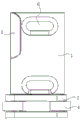
Fig. 1 is a schematic view of the present invention.
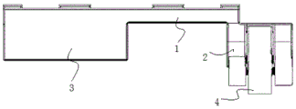
Fig. 2 is a schematic diagram of an embodiment of the present disclosure.
Fig. 3 is a side view of fig. 2.
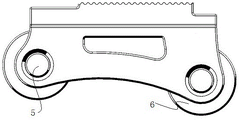
Fig. 4 is a schematic view of a guiding mechanism according to an embodiment of the present disclosure
Shown in the figure: 1 connecting seat, 2 cassette, 3 dog, 4 gyro wheels, 5 axles, 6 spread grooves.
Detailed Description
The present invention will be further described with reference to the accompanying drawings.
As shown in the figure, the locking fastener for opening and closing the electric door and window comprises a connecting seat 1, wherein one end of the connecting seat is fixedly connected with a guide mechanism, and one side of the connecting seat is fixedly connected with a stop block 3; the guiding mechanism comprises a clamping seat 2, at least one roller 4 is arranged in the clamping seat, and the clamping seat is fixedly connected with a connecting seat. The door and window frame is fixed through the connecting seat, the stop block is matched with the electric door and window to fix the position of the electric door and window, and the guide mechanism is matched with the roller on the door and window to work, so that the running track of the electric door and window is ensured.
In order to facilitate the connection of the connecting seat and the electric door and window frame, the connecting seat is provided with a connecting groove 6 for installing a fixing screw and the like.
In order to facilitate the fixation of the electric door and window, the stop block is provided with a smooth curved surface which is matched with the electric door and window, so that the electric door and window can run conveniently.
In order to ensure that the electric door and window smoothly runs by the work of the guide mechanism, the roller is connected with the clamping seat through the shaft 5.
In order to ensure smooth opening and closing of the electric door and window, the contact surface of the clamping seat and the electric door and window is provided with a smooth curved surface, so that the roller on the electric door and window can work conveniently.
In the embodiment 1, the connecting seat is rectangular and is provided with a connecting groove 6, the bottom of the connecting seat is fixedly connected with a guide mechanism, and the guide mechanism consists of two fixing plates; the guide mechanism is provided with two rollers which are respectively positioned at two ends of the guide mechanism and are connected with the fixed plate through shafts. The side rigid coupling of connecting seat has the dog, and the dog is used for cooperating door and window's fixed spacing. Because the stop block and the guide mechanism are matched with the electric door and window to work, the working surface of the stop block and the guide mechanism is provided with a smooth curved surface so as to be better matched with the movement of the electric door and window.
The lock catch piece with the structure has the advantages of simple structure and convenience in manufacturing and mounting. The utility model discloses on being fixed in the door and window mount, cooperation door and window that can be fine opens and close work.
It should be known to those skilled in the art that the protection scheme of the present invention is not limited to the above-mentioned embodiments, and various permutations, combinations and transformations can be performed on the basis of the above-mentioned embodiments, without violating the spirit of the present invention, all the transformations performed by the present invention fall within the protection scope of the present invention.
Claims (5)
1. A lock catch piece for opening and closing an electric door and window is characterized by comprising a connecting seat (1), wherein one end of the connecting seat is fixedly connected with a guide mechanism, and one side of the connecting seat is fixedly connected with a stop block (3); the guide mechanism comprises a clamping seat (2), at least one roller (4) is arranged in the clamping seat, and the clamping seat is fixedly connected with the connecting seat.
2. The locking fastener for opening and closing of electric doors and windows as claimed in claim 1, wherein the connecting seat is provided with a connecting groove (6).
3. The locking fastener for opening and closing of electric doors and windows as claimed in claim 1, wherein said stopper has a smooth curved surface.
4. The fastener for opening and closing electric doors and windows according to claim 1, wherein the roller is connected with the clamping seat through a shaft (5).
5. The fastener for opening and closing the electric door and window according to any one of claims 1 to 4, wherein the locking seat is provided with a smooth curved surface.
Priority Applications (1)
| Application Number | Priority Date | Filing Date | Title |
|---|---|---|---|
| CN202021807451.3U CN214062659U (en) | 2020-08-26 | 2020-08-26 | Lock catch piece for opening and closing electric door and window |
Applications Claiming Priority (1)
| Application Number | Priority Date | Filing Date | Title |
|---|---|---|---|
| CN202021807451.3U CN214062659U (en) | 2020-08-26 | 2020-08-26 | Lock catch piece for opening and closing electric door and window |
Publications (1)
| Publication Number | Publication Date |
|---|---|
| CN214062659U true CN214062659U (en) | 2021-08-27 |
Family
ID=77385557
Family Applications (1)
| Application Number | Title | Priority Date | Filing Date |
|---|---|---|---|
| CN202021807451.3U Active CN214062659U (en) | 2020-08-26 | 2020-08-26 | Lock catch piece for opening and closing electric door and window |
Country Status (1)
| Country | Link |
|---|---|
| CN (1) | CN214062659U (en) |
-
2020
- 2020-08-26 CN CN202021807451.3U patent/CN214062659U/en active Active
Similar Documents
| Publication | Publication Date | Title |
|---|---|---|
| CN214062659U (en) | Lock catch piece for opening and closing electric door and window | |
| CN203308319U (en) | Sliding flat pressing door and window | |
| CN109296293B (en) | Side pressure attaches frame and uses its sliding door and window | |
| CN201705136U (en) | Rotary device for tilt and turn doors and windows | |
| CN216197749U (en) | Combined casement window structure capable of adjusting lighting | |
| CN215520488U (en) | Hinge for shower room | |
| CN215595346U (en) | Combined door and window | |
| CN101225727A (en) | Slightly-ventilating flat-opening transmission fastener for door and window | |
| CN219034336U (en) | Fastening device | |
| CN216157561U (en) | Locking structure of screen window | |
| CN213063285U (en) | Mechanical locking type automatic door opening and closing device | |
| CN211974725U (en) | Casement window with micro ventilation function | |
| CN216197533U (en) | Electric screw windowing device | |
| CN212837157U (en) | Lock for sliding door and window | |
| CN208089053U (en) | A kind of door and window reset lock | |
| CN216788216U (en) | Sealed timber | |
| CN221032096U (en) | Adjusting structure suitable for hidden guide rail | |
| CN216110312U (en) | Hidden intelligent electric opening and closing window | |
| CN220415225U (en) | Door and window system | |
| CN216476896U (en) | Automatic opening device for sliding door and window | |
| CN216341580U (en) | Novel lock body and sliding door | |
| CN213418907U (en) | Door and window with thermal-insulated effect | |
| CN211370181U (en) | Door with ventilation function | |
| CN2227723Y (en) | Multiposition free door and window | |
| CN220790911U (en) | Vertical shaft for adjusting door and window |
Legal Events
| Date | Code | Title | Description |
|---|---|---|---|
| GR01 | Patent grant | ||
| GR01 | Patent grant | ||
| TR01 | Transfer of patent right | ||
| TR01 | Transfer of patent right |
Effective date of registration: 20211130 Address after: 244000 No. 695, North Section of Taishan Avenue, Tongling City, Anhui Province Patentee after: Anhui Haiyuan smart home Co.,Ltd. Address before: 244000 building C2, Hangzhou Road, East Park, Tongling Economic and Technological Development Zone, Anhui Province Patentee before: Tongling shouchuang Technology Co.,Ltd. |