CN214024289U - Positioning platform with welding jig - Google Patents
Positioning platform with welding jig Download PDFInfo
- Publication number
- CN214024289U CN214024289U CN202022875785.0U CN202022875785U CN214024289U CN 214024289 U CN214024289 U CN 214024289U CN 202022875785 U CN202022875785 U CN 202022875785U CN 214024289 U CN214024289 U CN 214024289U
- Authority
- CN
- China
- Prior art keywords
- positioning
- adjusting rod
- workbench
- standard
- platform
- Prior art date
- Legal status (The legal status is an assumption and is not a legal conclusion. Google has not performed a legal analysis and makes no representation as to the accuracy of the status listed.)
- Active
Links
Images


Abstract
The utility model discloses a positioning platform with a welding fixture, which comprises a positioning platform and a welding fixture; the positioning platform comprises a workbench, and a plurality of standard positioning holes are formed in the workbench; the welding fixture comprises a positioning block and a clamping device; the positioning block is provided with a through long waist round hole and fixedly connected with the workbench through a positioning pin which sequentially penetrates through the long waist round hole and the standard positioning hole; the side surface of the workpiece is horizontally positioned by abutting against the positioning block; the clamp comprises a positioning column, the bottom of the positioning column is arranged in a standard positioning hole, a transverse shaft sleeve is arranged at the top of the standard positioning hole, a movable horizontal adjusting rod is arranged in the transverse shaft sleeve, a longitudinal shaft sleeve is arranged at the end part of the horizontal adjusting rod, a movable vertical adjusting rod is arranged in the longitudinal shaft sleeve, a limiting block is arranged at the top of the vertical adjusting rod, a pressure head is arranged at the top of the vertical adjusting rod, and the pressure head realizes vertical positioning through the top surface of a pressed workpiece.
Description
Technical Field
The utility model relates to a welding equipment field, specifically speaking, in particular to positioning platform with welding jig.
Background
Referring to fig. 1 and 2, the existing welding fixture only fixes a workpiece on a platform, and is difficult to be used with other fixtures, and the limitation is large. In addition, because no standardized reference object is used for determining the position, the position cannot be conveniently positioned, and the welding robot cannot quickly find the reference point, so that the batched quick welding work cannot be carried out, and only manual welding can be used.
SUMMERY OF THE UTILITY MODEL
An object of the utility model is to provide a positioning platform with welding jig to the not enough among the prior art to solve the problem that exists among the prior art.
The utility model provides a technical problem can adopt following technical scheme to realize:
a positioning platform with welding fixtures comprises a positioning platform and a plurality of welding fixtures arranged on the positioning platform;
the positioning platform comprises a workbench, a plurality of supporting legs are arranged at the bottom of the workbench, the top surface of the workbench is a positioning surface, and a plurality of standard positioning holes are formed in the positioning surface;
the welding fixture comprises a positioning block and a clamping device;
the positioning block is provided with a through long waist round hole and fixedly connected with the workbench through a positioning pin which sequentially penetrates through the long waist round hole and the standard positioning hole; the side surface of the workpiece is horizontally positioned by abutting against the positioning block;
the clamp comprises a positioning column, the bottom of the positioning column is arranged in a standard positioning hole, a transverse shaft sleeve is arranged at the top of the standard positioning hole, a movable horizontal adjusting rod is arranged in the transverse shaft sleeve, a longitudinal shaft sleeve is arranged at the end part of the horizontal adjusting rod, a movable vertical adjusting rod is arranged in the longitudinal shaft sleeve, a limiting block is arranged at the top of the vertical adjusting rod, a pressure head is arranged at the top of the vertical adjusting rod, and the pressure head realizes vertical positioning through the top surface of a pressed workpiece.
Furthermore, the supporting legs are four in number and are respectively positioned at four corners of the bottom of the workbench.
Furthermore, the standard positioning holes are distributed in an array form.
Furthermore, the main body of the positioning block is of an L-shaped structure, the long edge of the L-shaped structure is fixedly connected with the workbench, and the short edge of the L-shaped structure is used for abutting against and positioning the side face of the workpiece.
Compared with the prior art, the beneficial effects of the utility model reside in that:
the positioning platform is provided with standard positioning holes distributed in an array manner, the positioning block and the clamping device are fixed on the positioning platform through the standard positioning holes, so that the horizontal positioning and the vertical positioning of the workpiece can be respectively realized,
the standardized positioning mode makes it become a welding frock that any work piece can both be general, does not confine to single product and can only use single welding frock, can conveniently cooperate welding robot welding, improves welding precision and welding efficiency.
Drawings
Fig. 1 is a schematic view of a conventional welding jig in use.
Fig. 2 is a schematic view of a conventional welding jig.
Fig. 3 is a schematic view of a positioning platform with a welding fixture according to the present invention.
Fig. 4 is a schematic view of the clamping device according to the present invention.
Fig. 5 is a schematic view of the positioning block of the present invention.
Detailed Description
In order to make the technical means, creation features, achievement purposes and functions of the present invention easy to understand, the present invention is further described below with reference to the following embodiments.
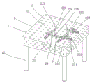
Referring to fig. 3, fig. 4 and fig. 5, the positioning platform with welding jigs of the present invention includes a positioning platform 1 and a plurality of welding jigs 2 disposed on the positioning platform 1;
the positioning platform 1 comprises a workbench 11, a plurality of supporting legs 12 are arranged at the bottom of the workbench 11, the top surface of the workbench 11 is a positioning surface, and a plurality of standard positioning holes 13 are formed in the positioning surface;
the welding fixture 2 comprises a positioning block 21 and a clamping device 22;
the positioning block 21 is provided with a through long waist round hole 211, and the positioning block 21 sequentially passes through the long waist round hole 211 and the standard positioning hole 13 through a positioning pin 212 to be fixedly connected with the workbench 11; the side surface of the workpiece 3 is horizontally positioned by abutting against the positioning block 21;
the clamping device 22 comprises a positioning column 221, the bottom of the positioning column 221 is arranged in the standard positioning hole 13, a transverse shaft sleeve 222 is arranged at the top of the standard positioning hole 13, a movable horizontal adjusting rod 223 is arranged in the transverse shaft sleeve 222, a longitudinal shaft sleeve 224 is arranged at the end of the horizontal adjusting rod 223, a movable vertical adjusting rod 225 is arranged in the longitudinal shaft sleeve 224, a limiting block 227 is arranged at the top of the vertical adjusting rod 225, a pressure head 226 is arranged at the top of the vertical adjusting rod 225, and the pressure head 226 realizes vertical positioning through pressing the top surface of the workpiece 3.
The supporting legs 12 are four in number and are respectively located at four corners of the bottom of the workbench 11.
The standard positioning holes 13 are distributed in an array.
The main body of the positioning block 21 is of an L-shaped structure, the long side of the L-shaped structure is used for being fixedly connected with the workbench 11, and the short side of the L-shaped structure is used for being abutted to and positioned on the side surface of the workpiece 3.
The working process of the utility model is as follows:
1) the positioning block 21 and the clamping device 22 are fixed on the positioning platform 1 through the standard positioning hole 13;
2) the workpiece 3 is placed on the positioning platform 1, and the workpiece 3 is horizontally positioned by abutting against the side surface of the positioning block 21;
3) the clamping device 3 is inserted into the standard hole 13 of the positioning platform 1, and the pressure head 226 of the clamping device is adjusted by the horizontal adjusting rod 223 and the vertical adjusting rod 225 to vertically position the workpiece 5.
The basic principles and the main features of the invention and the advantages of the invention have been shown and described above. It will be understood by those skilled in the art that the present invention is not limited to the above embodiments, and that the foregoing embodiments and descriptions are provided only to illustrate the principles of the present invention without departing from the spirit and scope of the present invention. The scope of the invention is defined by the appended claims and equivalents thereof.
Claims (4)
1. The utility model provides a positioning platform with welding jig which characterized in that: comprises a positioning platform (1) and a plurality of welding clamps (2) arranged on the positioning platform (1);
the positioning platform (1) comprises a workbench (11), a plurality of supporting legs (12) are arranged at the bottom of the workbench (11), the top surface of the workbench (11) is a positioning surface, and a plurality of standard positioning holes (13) are formed in the positioning surface;
the welding fixture (2) comprises a positioning block (21) and a clamping device (22);
the positioning block (21) is provided with a through long waist round hole (211), and the positioning block (21) sequentially penetrates through the long waist round hole (211) and the standard positioning hole (13) through a positioning pin (212) to be fixedly connected with the workbench (11); the side surface of the workpiece (3) is horizontally positioned by abutting against the positioning block (21);
the clamp (22) comprises a positioning column (221), the bottom of the positioning column (221) is arranged in a standard positioning hole (13), the top of the standard positioning hole (13) is provided with a transverse shaft sleeve (222), a movable horizontal adjusting rod (223) is arranged in the transverse shaft sleeve (222), a longitudinal shaft sleeve (224) is arranged at the end part of the horizontal adjusting rod (223), a movable vertical adjusting rod (225) is arranged in the longitudinal shaft sleeve (224), a limiting block (227) is arranged at the top of the vertical adjusting rod (225), a pressure head (226) is arranged at the top of the vertical adjusting rod (225), and the vertical positioning of the pressure head (226) is realized through the top surface of a compressed workpiece (3).
2. The positioning platform with the welding fixture of claim 1, wherein: the number of the supporting legs (12) is four, and the supporting legs are respectively positioned at four corners of the bottom of the workbench (11).
3. The positioning platform with the welding fixture of claim 1, wherein: the standard positioning holes (13) are distributed in an array form.
4. The positioning platform with the welding fixture of claim 1, wherein: the main body of the positioning block (21) is of an L-shaped structure, the long edge of the L-shaped structure is fixedly connected with the workbench (11), and the short edge of the L-shaped structure is used for being abutted against and positioned on the side surface of the workpiece (3).
Priority Applications (1)
| Application Number | Priority Date | Filing Date | Title |
|---|---|---|---|
| CN202022875785.0U CN214024289U (en) | 2020-12-04 | 2020-12-04 | Positioning platform with welding jig |
Applications Claiming Priority (1)
| Application Number | Priority Date | Filing Date | Title |
|---|---|---|---|
| CN202022875785.0U CN214024289U (en) | 2020-12-04 | 2020-12-04 | Positioning platform with welding jig |
Publications (1)
| Publication Number | Publication Date |
|---|---|
| CN214024289U true CN214024289U (en) | 2021-08-24 |
Family
ID=77383488
Family Applications (1)
| Application Number | Title | Priority Date | Filing Date |
|---|---|---|---|
| CN202022875785.0U Active CN214024289U (en) | 2020-12-04 | 2020-12-04 | Positioning platform with welding jig |
Country Status (1)
| Country | Link |
|---|---|
| CN (1) | CN214024289U (en) |
-
2020
- 2020-12-04 CN CN202022875785.0U patent/CN214024289U/en active Active
Similar Documents
| Publication | Publication Date | Title |
|---|---|---|
| CN104741954A (en) | Double-oblique-face double-way floating pairing workpiece automatic clamping jig | |
| CN105414860A (en) | Welding fixture for automobile seat part | |
| CN205363105U (en) | Car seat part welding frock | |
| CN202461869U (en) | Workpiece positioning device for repair welding operation | |
| CN214024289U (en) | Positioning platform with welding jig | |
| CN214722492U (en) | Bench clamp | |
| CN218051454U (en) | Clamp for planer type milling machine | |
| CN214814926U (en) | Chuck positioning and clamping device | |
| CN208496171U (en) | It is a kind of for welding the weld fixture apparatus of headstock seat support | |
| CN208628978U (en) | A kind of engine cylinder body processing hydraulic fixture | |
| CN207942203U (en) | A kind of A, B column positioning tool | |
| CN213918257U (en) | Spline housing marking device with adjustable quick positioning function | |
| CN201736049U (en) | Pneumatic clamp | |
| CN206277080U (en) | A kind of automobile back door frame weld jig | |
| CN215358018U (en) | Novel vice | |
| CN206153932U (en) | Milling machine jig | |
| CN110434372A (en) | A kind of thin plate drilling tool fixture and its clamping method | |
| CN214722549U (en) | Pneumatic clamping flat tongs | |
| CN204935179U (en) | A kind of positioning clamping device of housing bore hole | |
| CN219945307U (en) | General processing frock of piece about crawler-type base support | |
| CN220806954U (en) | Penetrating slide rail type vice | |
| CN213135122U (en) | Drilling equipment capable of avoiding deviation of oil duct of machining brake | |
| CN215035365U (en) | Simple and easy quick circular workpiece clamping device of adjustable bore | |
| CN220217481U (en) | Vertical machining center with positioning structure | |
| CN215239312U (en) | General forked tail anchor clamps that use on five machining centers |
Legal Events
| Date | Code | Title | Description |
|---|---|---|---|
| GR01 | Patent grant | ||
| GR01 | Patent grant |