CN214023533U - Clamping equipment for production and processing of turning parts - Google Patents
Clamping equipment for production and processing of turning parts Download PDFInfo
- Publication number
- CN214023533U CN214023533U CN202023295713.5U CN202023295713U CN214023533U CN 214023533 U CN214023533 U CN 214023533U CN 202023295713 U CN202023295713 U CN 202023295713U CN 214023533 U CN214023533 U CN 214023533U
- Authority
- CN
- China
- Prior art keywords
- production
- electric telescopic
- processing
- arc
- telescopic handle
- Prior art date
- Legal status (The legal status is an assumption and is not a legal conclusion. Google has not performed a legal analysis and makes no representation as to the accuracy of the status listed.)
- Active
Links
Images


Abstract
The utility model discloses a turning is centre gripping equipment for production and processing relates to turning technical field, and is complicated for solving current turning is clamping equipment for production and processing structure, inconvenient problem of adjusting use height. The utility model discloses a turning production and processing workstation, including turning production and processing workstation, protection base top, central electric telescopic handle is installed to the intermediate position department of protection base top, the base is placed in center electric telescopic handle's top is installed, the inside of protection base is provided with the installation spout, the internally mounted of installation spout has linear motor, fixed slider is installed to linear motor's top, electric telescopic handle is installed to fixed slider's top, the spacing grip block of first half arc is installed to one side of electric telescopic handle top.
Description
Technical Field
The utility model relates to a turning technical field specifically is a clamping equipment is used in turning production and processing.
Background
Generally, the method refers to lathe machining, and the lathe machining is a part of mechanical machining; lathe machining mainly comprises the steps of turning a rotating workpiece by using a lathe tool; the lathe can also be correspondingly processed by a drill bit, a reamer, a screw tap, a die, a knurling tool and the like; the lathe is mainly used for processing shafts, discs, sleeves and other workpieces with rotating surfaces, and is the most widely used type of machine tool in mechanical manufacturing and repair factories; rotating the workpiece, and cutting and processing the turning tool to move linearly or curvilinearly in a plane; turning is generally performed on a lathe and is used for processing an inner cylindrical surface, an outer cylindrical surface, an end surface, a conical surface, a forming surface, a thread and the like of a workpiece; when the inner and outer cylindrical surfaces are turned, the turning tool moves along the direction parallel to the rotation axis of the workpiece; when the end face is turned or the workpiece is cut off, the turning tool horizontally moves along the direction vertical to the rotation axis of the workpiece; if the movement track of the turning tool forms an oblique angle with the rotation axis of the workpiece, a conical surface can be processed; the surface of the turning-formed rotary body can adopt a forming tool method or a tool tip track method.
However, the existing clamping equipment for producing and processing the turning piece is complex in structure and inconvenient to adjust the height; therefore, the existing requirements are not met, and a clamping device for the production and processing of turning pieces is provided for the purpose.
SUMMERY OF THE UTILITY MODEL
An object of the utility model is to provide a turning is centre gripping equipment for production and processing to it is complicated to provide current turning for production and processing centre gripping equipment structure in the above-mentioned background art of solution, the inconvenient problem of adjusting use height.
In order to achieve the above object, the utility model provides a following technical scheme: the utility model provides a turning production and processing uses centre gripping equipment, includes turning production and processing workstation, the internally mounted of turning production and processing workstation has the protection base, the intermediate position department of protection base top installs central electric telescopic handle, central electric telescopic handle's top is installed and is placed the base, the inside of protection base is provided with the installation spout, the internally mounted of installation spout has linear motor, fixed slider is installed to linear motor's top, electric telescopic handle is installed to fixed slider's top, the spacing grip block of first half arc is installed to one side of electric telescopic handle top.
Preferably, the turning piece production and processing workbench is externally provided with a fixed edge block, and the fixed edge block is internally provided with a fixed block.
Preferably, electric telescopic handle is provided with four, and four electric telescopic handle all set up relatively, fixed slider and electric telescopic handle and the equal fixed connection of linear motor.
Preferably, the front end of protection base top installs the spacing grip block of second semi-arc, the rear end of the spacing grip block of second semi-arc is installed the spacing grip block of fourth semi-arc relatively, the spacing grip block of first semi-arc is installed the spacing grip block of third semi-arc relatively.
Preferably, the connecting blocks are arranged in the first half-arc limiting clamping plate, the second half-arc limiting clamping plate, the third half-arc limiting clamping plate and the fourth half-arc limiting clamping plate.
Preferably, mounting plate is installed to center electric telescopic handle's below, mounting plate and protection base pass through set screw and connect, the internally mounted who places the base has the protection center to fill up, the protection center fills up and places the base and paste the connection.
Compared with the prior art, the beneficial effects of the utility model are that:
1. the utility model discloses a set up first half arc spacing grip block, second half arc spacing grip block, third half arc spacing grip block, fourth half arc spacing grip block and electric telescopic handle, during the use, drive first half arc spacing grip block, second half arc spacing grip block, third half arc spacing grip block and fourth half arc spacing grip block simultaneously to the inside lateral movement to place the outside of the turning piece above placing the base spacing, thereby carry out the centre gripping, conveniently carry out the centre gripping to turning pieces of equidimension not, and through installing electric telescopic handle, be convenient for adjust the height of work centre gripping, convenient operation, whole performance is perfect;
2. the utility model discloses a set up central electric telescopic handle, placed base and protection center pad, during the use, confirm the height of centre gripping work through center of regulation electric telescopic handle, place the turning piece again and fill up in placing the inside protection center of base, protection center pad protectiveness is strong, convenient to use centre gripping, easy and simple to handle, structural stability is high.
Drawings
FIG. 1 is a front view of a clamping apparatus for manufacturing a turning part according to the present invention;
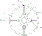
FIG. 2 is a top view of the clamping apparatus for manufacturing and processing a turning part according to the present invention;
fig. 3 is a schematic structural view of the base of the present invention.
In the figure: 1. a turning part production and processing workbench; 2. a fixed block; 3. a protective base; 4. fixing the sliding block; 5. an electric telescopic rod; 6. a first semi-arc limiting clamping plate; 7. a second semi-arc limiting clamping plate; 8. a third semi-arc limiting clamping plate; 9. a central electric telescopic rod; 10. placing a base; 11. fixing the edge block; 12. a fourth semi-arc limiting clamping plate; 13. a linear motor; 14. connecting blocks; 15. installing a chute; 16. mounting a bottom plate; 17. a set screw; 18. a protective center pad.
Detailed Description
The technical solutions in the embodiments of the present invention will be described clearly and completely with reference to the accompanying drawings in the embodiments of the present invention, and it is obvious that the described embodiments are only some embodiments of the present invention, not all embodiments.
Referring to fig. 1-3, the present invention provides an embodiment: the utility model provides a turning production and processing uses centre gripping equipment, including turning production and processing workstation 1, the internally mounted of turning production and processing workstation 1 has protection base 3, the intermediate position department of protection base 3 top installs central electric telescopic handle 9, the top of central electric telescopic handle 9 is installed and is placed base 10, be convenient for place the use, the inside of protection base 3 is provided with installation spout 15, the internally mounted of installation spout 15 has linear motor 13, fixed sliding block 4 is installed to linear motor 13's top, electric telescopic handle 5 is installed to fixed sliding block 4's top, the spacing grip block 6 of first half arc is installed to one side of electric telescopic handle 5 top, be convenient for fix turning.
Further, the fixed limit piece 11 is installed to the externally mounted of turning piece production and processing workstation 1, and the internally mounted of fixed limit piece 11 has fixed block 2, connects reliable and stable.
Further, electric telescopic handle 5 is provided with four, and four electric telescopic handle 5 homogeneous phase are relative to be set up, and the fixed sliding block 4 is convenient for adjust the operating height with electric telescopic handle 5 and the equal fixed connection of linear electric motor 13.
Further, the second semi-arc limiting clamping plate 7 is installed at the front end above the protective base 3, the fourth semi-arc limiting clamping plate 12 is installed at the rear end of the second semi-arc limiting clamping plate 7 in a relative mode, the third semi-arc limiting clamping plate 8 is installed on the first semi-arc limiting clamping plate 6 in a relative mode, and turning pieces with different diameters can be conveniently fixed.
Furthermore, connecting blocks 14 are arranged inside one sides of the first half-arc limiting clamping plate 6, the second half-arc limiting clamping plate 7, the third half-arc limiting clamping plate 8 and the fourth half-arc limiting clamping plate 12, and the connection is stable.
Further, mounting plate 16 is installed to central electric telescopic handle 9's below, and mounting plate 16 and protection base 3 pass through set screw 17 to be connected, and the internally mounted who places base 10 has protection center to fill up 18, and protection center fills up 18 and places base 10 and pastes the connection, and the protectiveness is strong.
The working principle is as follows: when in use, the turning piece production and processing workbench 1 is fixed in use through the fixing block 2, the protective base 3 has good protection performance, the central electric telescopic rod 9 is started again, the mounting bottom plate 16 and the fixing screws 17 ensure the mounting stability of the central electric telescopic rod 9, the central electric telescopic rod 9 drives the placing base 10 to move upwards to facilitate the adjustment of the height of the turning piece to be clamped, after the height is determined, the turning piece is placed on the protective central pad 18 inside, the protective central pad 18 has strong protection performance, the four electric telescopic rods 5 are started again, the electric telescopic rods 5 respectively drive the first semi-arc limiting clamping plate 6, the second semi-arc limiting clamping plate 7, the third semi-arc limiting clamping plate 8 and the fourth semi-arc limiting clamping plate 12 to move upwards to reach the clamping height of the turning piece, the connecting block 14 has good connection stability, and then the linear motor 13 inside the mounting chute 15 is started, linear motor 13 work drives fixed slider 4 motion to make the spacing grip block of first half arc 6, the spacing grip block of second half arc 7, the spacing grip block of third half arc 8 and the spacing grip block of fourth half arc 12 move the outside that is close to the turning respectively to the inboard, carry out spacing centre gripping to the outside of turning, stability is high, and conveniently carries out the centre gripping to the turning of big minor diameter difference.
It is obvious to a person skilled in the art that the invention is not restricted to details of the above-described exemplary embodiments, but that it can be implemented in other specific forms without departing from the spirit or essential characteristics of the invention. The present embodiments are therefore to be considered in all respects as illustrative and not restrictive, the scope of the invention being indicated by the appended claims rather than by the foregoing description, and all changes which come within the meaning and range of equivalency of the claims are therefore intended to be embraced therein. Any reference sign in a claim should not be construed as limiting the claim concerned.
Claims (6)
1. The utility model provides a clamping equipment is used in turning production and processing, includes turning production machining workstation (1), its characterized in that: the utility model discloses a turning production and processing workstation, including turning production and processing workstation (1), the internally mounted of turning production and processing workstation (1) has protection base (3), the intermediate position department of protection base (3) top installs central electric telescopic handle (9), the top of central electric telescopic handle (9) is installed and is placed base (10), the inside of protection base (3) is provided with installation spout (15), the internally mounted of installation spout (15) has linear motor (13), fixed slider (4) are installed to the top of linear motor (13), electric telescopic handle (5) are installed to the top of fixed slider (4), the spacing grip block of first half arc (6) is installed to one side of electric telescopic handle (5) top.
2. The clamping device for the production and processing of turned parts according to claim 1, characterized in that: the external mounting of turning piece production and processing workstation (1) has fixed limit piece (11), the internally mounted of fixed limit piece (11) has fixed block (2).
3. The clamping device for the production and processing of turned parts according to claim 1, characterized in that: electric telescopic handle (5) are provided with four, and four electric telescopic handle (5) homogeneous phase are relative to each other to be set up, fixed slider (4) and electric telescopic handle (5) and the equal fixed connection of linear motor (13).
4. The clamping device for the production and processing of turned parts according to claim 1, characterized in that: the front end of protection base (3) top is installed the spacing grip block of second semi-arc (7), the rear end of the spacing grip block of second semi-arc (7) is relative to be installed the spacing grip block of fourth semi-arc (12), the spacing grip block of first semi-arc (6) is relative to be installed the spacing grip block of third semi-arc (8).
5. The clamping device for the production and processing of turned parts according to claim 4, characterized in that: the connecting blocks (14) are arranged inside one side of the first half-arc-shaped limiting clamping plate (6), the second half-arc-shaped limiting clamping plate (7), the third half-arc-shaped limiting clamping plate (8) and the fourth half-arc-shaped limiting clamping plate (12).
6. The clamping device for the production and processing of turned parts according to claim 1, characterized in that: mounting plate (16) are installed to the below of center electric telescopic handle (9), mounting plate (16) and protection base (3) are connected through set screw (17), the internally mounted who places base (10) has protection center pad (18), protection center pad (18) and place base (10) and paste the connection.
Priority Applications (1)
| Application Number | Priority Date | Filing Date | Title |
|---|---|---|---|
| CN202023295713.5U CN214023533U (en) | 2020-12-30 | 2020-12-30 | Clamping equipment for production and processing of turning parts |
Applications Claiming Priority (1)
| Application Number | Priority Date | Filing Date | Title |
|---|---|---|---|
| CN202023295713.5U CN214023533U (en) | 2020-12-30 | 2020-12-30 | Clamping equipment for production and processing of turning parts |
Publications (1)
| Publication Number | Publication Date |
|---|---|
| CN214023533U true CN214023533U (en) | 2021-08-24 |
Family
ID=77344690
Family Applications (1)
| Application Number | Title | Priority Date | Filing Date |
|---|---|---|---|
| CN202023295713.5U Active CN214023533U (en) | 2020-12-30 | 2020-12-30 | Clamping equipment for production and processing of turning parts |
Country Status (1)
| Country | Link |
|---|---|
| CN (1) | CN214023533U (en) |
-
2020
- 2020-12-30 CN CN202023295713.5U patent/CN214023533U/en active Active
Similar Documents
| Publication | Publication Date | Title |
|---|---|---|
| CN209754598U (en) | clamping device for machine tool machining | |
| CN111618670A (en) | Adjustable twist drill grinding device | |
| CN213105647U (en) | Boring and milling machining center for machining high-pressure pump body | |
| CN209811765U (en) | Lathe quick clamping device | |
| CN216503388U (en) | Turning and milling combined type machine tool | |
| CN212885235U (en) | Drilling machine capable of achieving multidirectional punching | |
| CN213003150U (en) | Electric spark machining clamp | |
| CN214023533U (en) | Clamping equipment for production and processing of turning parts | |
| CN103707136A (en) | WEDM-based (wire-cut electric discharge machining based) twist drill rear face forming device | |
| CN213647151U (en) | Clamp for machining wind power gearbox shell | |
| CN215617925U (en) | Workstation convenient to pincers worker uses | |
| CN213917917U (en) | Novel tool clamp | |
| CN211991038U (en) | Drilling machine for machining hardware equipment | |
| CN210006712U (en) | Positioning device of photovoltaic silicon wafer inserting machine | |
| CN215035727U (en) | Lathe with quick tool changing function | |
| CN214922195U (en) | Drilling and reaming all-in-one machine capable of accurately positioning workpiece | |
| CN219562236U (en) | High-precision machining center tool | |
| CN212371692U (en) | Composite workpiece clamp for cutting machine tool | |
| CN212761123U (en) | Brake disc turning device | |
| CN219598379U (en) | Friction stir welding device with adjustable angle | |
| CN220575312U (en) | Frock clamp and lathe | |
| CN212734710U (en) | Rotor manufacturing device for motor | |
| CN220718022U (en) | Linear cutting auxiliary clamping fixture | |
| CN211991264U (en) | Cutting machine tool | |
| CN217253050U (en) | Positioning device for workpiece on workbench of radial drilling machine |
Legal Events
| Date | Code | Title | Description |
|---|---|---|---|
| GR01 | Patent grant | ||
| GR01 | Patent grant |