Tee bend slot pipe fitting gas tightness check out test set
Technical Field
The utility model relates to an air tightness detects technical field, especially relates to a tee bend slot pipe fitting gas tightness check out test set.
Background
The tee pipe fitting is provided with three ports, namely an inlet and two outlets; or two inlets and one outlet, and the chemical pipe fitting has T shape, Y shape, equal diameter pipe orifice and different diameter pipe orifice and is used for the convergence of three identical or different pipelines; the main function of the tee is to change the direction of the fluid.
When current T type tee bend slot pipe fitting carried out the gas tightness to it and detected, some seal up tee bend slot pipe fitting through the manual work, and monitoring efficiency is low and extravagant manpower resources, and some monitor through gas tightness check out test set, but can only seal up the monitoring to tee bend slot pipe fitting of specific model and size, and application scope is narrow.
SUMMERY OF THE UTILITY MODEL
The utility model aims at solving the defects in the prior art, and provides a three-way groove pipe fitting air tightness detection device which can blow air to a three-way groove pipe fitting through an air blowing mechanism, is convenient for subsequent detection, and can display a detection structure on a display screen, so that the detection device is intuitive and clear; the three-way groove pipe fittings of different types and sizes can be sealed through the dismounting mechanism, and the application range is wide.
In order to achieve the above purpose, the utility model adopts the following technical scheme:
the utility model provides a tee bend slot pipe fitting gas tightness check out test set, includes the base, fixedly connected with L template on the base, two fixedly connected with place the piece on the base, two equal fixedly connected with pneumatic cylinder on placing the piece, fixedly connected with electric telescopic handle on the L template, electric telescopic handle's the output and the equal fixedly connected with installation piece of the output of two pneumatic cylinders, it is three all install the sealing plug on the installation piece, fixedly connected with air compressor on the L template, be equipped with the mechanism of blowing between the sealing plug of air compressor and upper end, it is three all be equipped with the disassembly body between installation piece and its the sealing plug that corresponds, install the display screen on the L template, the right-hand member install pressure monitor on the sealing plug.
Preferably, the air blowing mechanism comprises an air pipe fixedly connected with an air compressor, the air pipe penetrates through the L-shaped plate and is fixedly connected with the L-shaped plate, the other end of the air pipe is fixedly connected with the mounting block at the uppermost end, a first ventilation channel is arranged in the mounting block, the air pipe is communicated with the first ventilation channel, a second ventilation channel is arranged in the sealing plug, the first ventilation channel is communicated with the second ventilation channel, a one-way valve is arranged in the second ventilation channel, and the one-way valve is fixedly connected with the sealing plug.
Preferably, the disassembling mechanism comprises a rotating rod which is arranged in the mounting block and is rotationally connected with the mounting block, one end of the rotating rod penetrates through the mounting block, the rotating rod is fixedly connected with a handle, the other end of the rotating rod is fixedly connected with a first bevel gear, the first bevel gear is rotationally connected with the mounting block, the first bevel gear is meshed with two second bevel gears, the two second bevel gears are both rotationally connected with the mounting block, the back ends of the two second bevel gears are both fixedly connected with hollow rotating rods, the two hollow rotating rods are both rotationally connected with the mounting block, threaded rods which are in threaded connection with the hollow rotating rods are both arranged in the two hollow rotating rods in a penetrating manner, stoppers are both fixedly connected with the two threaded rods, the two stoppers are respectively and movably connected with the corresponding hollow rotating rods, and clamping rods are both fixedly connected with the two threaded rods, the clamping rods are connected with the mounting block in a sliding mode, two limiting grooves are formed in the sealing plug, the clamping rods are embedded into the limiting grooves corresponding to the clamping rods respectively, a layer of sealing ring is arranged on the outer wall of the sealing plug, and the sealing ring is abutted to the mounting block.
Preferably, the air tube is a plastic flexible hose.
Preferably, the outer wall of the handle is provided with a layer of rubber protective sleeve.
Preferably, the inner wall of the hollow rotating rod and the outer wall of the threaded rod are respectively provided with an internal thread and an external thread which are matched with each other.
Preferably, the clamping bars are provided in an L-shape.
Compared with the prior art, the utility model, its beneficial effect does:
1. the pneumatic cylinder is started, the output end of the pneumatic cylinder drives the mounting block and the sealing plug to move relatively, the two ends of the three-way groove pipe fitting are sealed, the electric telescopic rod is started again, the output end of the electric telescopic rod drives the mounting block and the sealing plug on the upper end to move downwards, and the operation is simple until the upper end of the three-way groove pipe fitting is sealed.
2. Starting the air compressor, the air compressor passes through trachea, first air passage, second air passage and to tee bend slot pipe fitting transported gas, can monitor the atmospheric pressure in the tee bend slot pipe fitting through pressure monitor to can show the numerical value of monitoring on the display screen, directly observe, the monitoring of being convenient for.
3. Hold the handle and rotate, drive the rotary rod, first bevel gear, second bevel gear, the cavity dwang is rotated, make the stopper at both ends, the threaded rod, the supporting rod moves back of the body relatively, break away from the spacing groove and can take off the sealing plug and change until the supporting rod, after having changed, reverse twist grip, make the supporting rod move in opposite directions until embedding spacing inslot fix the sealing plug can, can seal up the tee bend slot pipe fitting of different models and bore size through changing different sealing plugs, and then carry out the gas tightness and detect, application scope is wide.
In conclusion, the air blowing mechanism can blow air to the three-way groove pipe fitting, so that subsequent detection is facilitated, and the detection structure can be displayed on the display screen, so that the detection is visual and clear; the three-way groove pipe fittings of different types and sizes can be sealed through the dismounting mechanism, and the application range is wide.
Drawings
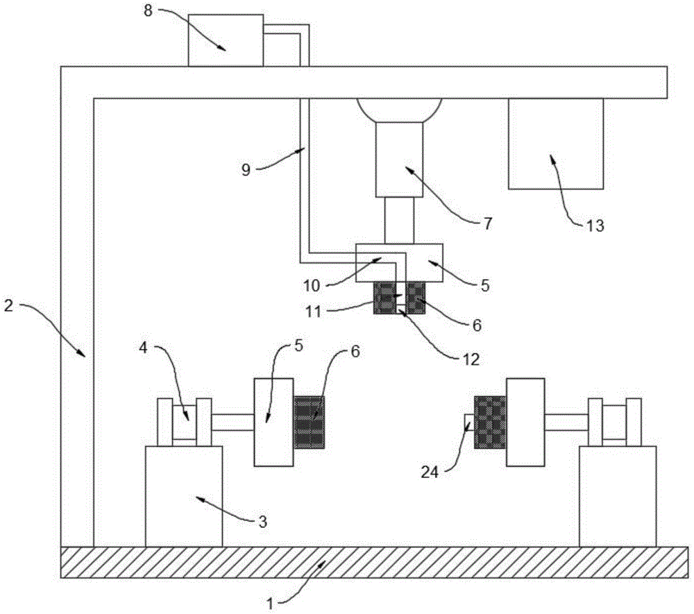
Fig. 1 is a cross-sectional view of a three-way groove pipe fitting air tightness detection device provided by the present invention;
FIG. 2 is a sectional view of a detaching mechanism of the three-way groove pipe fitting airtightness detection apparatus provided by the present invention;
fig. 3 is the utility model provides a three-way slot pipe fitting gas tightness check out test set's disassembly body side view.
In the figure: the device comprises a base 1, a 2L-shaped plate, a 3 placement block, a 4 hydraulic cylinder, a 5 installation block, a 6 sealing plug, a 7 electric telescopic rod, an 8 air compressor, a 9 air pipe, a 10 first ventilation channel, a 11 second ventilation channel, a 12 one-way valve, a 13 display screen, a 14 rotating rod, a 15 handle, a 16 first bevel gear, a 17 second bevel gear, a 18 hollow rotating rod, a 19 limiting block, a 20 threaded rod, a 21 clamping rod, a 22 limiting groove, a 23 sealing ring and a 24 pressure monitor.
Detailed Description
The technical solutions in the embodiments of the present invention will be described clearly and completely with reference to the accompanying drawings in the embodiments of the present invention, and it is obvious that the described embodiments are only some embodiments of the present invention, not all embodiments.
Referring to fig. 1-3, a tee bend slot pipe fitting gas tightness check out test set, including base 1, fixedly connected with L template 2 on the base 1, two fixedly connected with place piece 3 on the base 1, two are placed equal fixedly connected with pneumatic cylinder 4 on the piece 3, fixedly connected with electric telescopic handle 7 on the L template 2, the output of electric telescopic handle 7 and the equal fixedly connected with installation piece 5 of the output of two pneumatic cylinders 4, all install sealing plug 6 on three installation piece 5, seal tee bend slot pipe fitting through sealing plug 6.
An air compressor 8 is fixedly connected on the L-shaped plate 2, an air blowing mechanism is arranged between the air compressor 8 and a sealing plug 6 at the upper end, the air blowing mechanism comprises an air pipe 9 fixedly connected with the air compressor 8, the air pipe 9 is a plastic telescopic hose, the stretching or compression can be realized, the air pipe 9 penetrates through the L-shaped plate 2 and is fixedly connected with the L-shaped plate, the other end of the air pipe 9 is fixedly connected with the mounting block 5 at the uppermost end, a first ventilation channel 10 is arranged in the mounting block 5, the air pipe 9 is communicated with the first ventilation channel 10, a second ventilation channel 11 is arranged in the sealing plug 6, the first ventilation channel 10 is communicated with the second ventilation channel 11, a one-way valve 12 is arranged in the second ventilation channel 11, the one-way valve 12 is fixedly connected with the sealing plug 6, air enters the three-way groove pipe fitting through the one-way valve 12, and air can be prevented from flowing into the second vent passage 11 and the first vent passage 10 through the check valve 12.
The three mounting blocks 5 and the corresponding sealing plugs 6 are provided with dismounting mechanisms, each dismounting mechanism comprises a rotary rod 14 which is arranged in the mounting block 5 and is rotatably connected with the mounting block, one end of each rotary rod 14 penetrates through the mounting block 5, each rotary rod 14 is fixedly connected with a handle 15, the outer wall of each handle 15 is provided with a layer of rubber protective sleeve to provide comfort for people, the other end of each rotary rod 14 is fixedly connected with a first bevel gear 16, each first bevel gear 16 is rotatably connected with the mounting block 5, each first bevel gear 16 is meshed with two second bevel gears 17, each two second bevel gears 17 are rotatably connected with the mounting block 5, the opposite ends of each two second bevel gears 17 are fixedly connected with hollow rotary rods 18, each two hollow rotary rods 18 are rotatably connected with the mounting block 5, each two hollow rotary rod 18 is internally provided with a threaded rod 20 in threaded connection with the corresponding hollow rotary rod 18, and the inner wall of each hollow rotary rod 18 and the outer wall of the threaded rod 20 are respectively provided with matched internal threads and external threads, equal fixedly connected with stopper 19 on two threaded rods 20, two stopper 19 respectively rather than the cavity dwang 18 swing joint who corresponds, cavity dwang 18 is rotatory to drive threaded rod 20 and stopper 19 removal, cavity dwang 18 and stopper 19 are relative between not only rotatory but also remove, the equal fixedly connected with supporting rod 21 of two threaded rods 20, supporting rod 21 sets up to the L type, two supporting rod 21 all with installation piece 5 sliding connection, be equipped with two spacing grooves 22 on the sealing plug 6, two supporting rod 21 imbed respectively and set up rather than the spacing groove 22 who corresponds, the outer wall of sealing plug 6 is equipped with one deck sealing washer 23, it is sealed with second air passage 11 to ensure first air passage 10 of upper end, sealing washer 23 offsets with installation piece 5, install display screen 13 on the L template 2, install pressure monitor 24 on the right-hand member's the 6, pressure monitor 24 will record on the data transfer display screen 13.
In the utility model, when the worker needs to detect the air tightness of the three-way groove pipe fitting, as long as the hydraulic cylinder 4 is started, the output end of the hydraulic cylinder 4 drives the mounting block 5 and the sealing plug 6 at the lower end to move relatively, the two ends of the three-way groove pipe fitting are sealed, the electric telescopic rod 7 is started again, the output end of the electric telescopic rod 7 drives the mounting block 5 and the sealing plug 6 at the upper end to move downwards until the upper end of the three-way groove pipe fitting is sealed, and the operation is simple; after sealing is completed, the air compressor 8 is started, the air compressor 8 conveys air to the three-way groove pipe fitting through the air pipe 9, the first ventilation channel 10 and the second ventilation channel 11, the air pressure in the three-way groove pipe fitting can be monitored through the pressure monitor 24, and a monitored numerical value can be displayed on the display screen 13, so that the air compressor is intuitive and convenient to monitor; rotate through holding handle 15, drive rotary rod 14, first bevel gear 16, second bevel gear 17, cavity dwang 18 rotates, make the stopper 19 at both ends, threaded rod 20, supporting rod 21 moves back to back relatively, can take off sealing plug 6 and change until supporting rod 21 breaks away from spacing groove 22, after having changed, reverse twist grip 15, make supporting rod 21 move in opposite directions until imbedding spacing groove 22 in fix sealing plug 6 can, can seal the tee bend slot pipe fitting of different models and bore size through changing different sealing plugs 6, and then carry out the gas tightness and detect, wide application scope.
The above, only be the concrete implementation of the preferred embodiment of the present invention, but the protection scope of the present invention is not limited thereto, and any person skilled in the art is in the technical scope of the present invention, according to the technical solution of the present invention and the utility model, the concept of which is equivalent to replace or change, should be covered within the protection scope of the present invention.