CN213977458U - A cooling device for recycled concrete production - Google Patents
A cooling device for recycled concrete production Download PDFInfo
- Publication number
- CN213977458U CN213977458U CN202023102328.4U CN202023102328U CN213977458U CN 213977458 U CN213977458 U CN 213977458U CN 202023102328 U CN202023102328 U CN 202023102328U CN 213977458 U CN213977458 U CN 213977458U
- Authority
- CN
- China
- Prior art keywords
- pipe
- chamber
- outlet pipe
- cooling
- water outlet
- Prior art date
- Legal status (The legal status is an assumption and is not a legal conclusion. Google has not performed a legal analysis and makes no representation as to the accuracy of the status listed.)
- Expired - Fee Related
Links
Images

Classifications
-
- Y—GENERAL TAGGING OF NEW TECHNOLOGICAL DEVELOPMENTS; GENERAL TAGGING OF CROSS-SECTIONAL TECHNOLOGIES SPANNING OVER SEVERAL SECTIONS OF THE IPC; TECHNICAL SUBJECTS COVERED BY FORMER USPC CROSS-REFERENCE ART COLLECTIONS [XRACs] AND DIGESTS
- Y02—TECHNOLOGIES OR APPLICATIONS FOR MITIGATION OR ADAPTATION AGAINST CLIMATE CHANGE
- Y02W—CLIMATE CHANGE MITIGATION TECHNOLOGIES RELATED TO WASTEWATER TREATMENT OR WASTE MANAGEMENT
- Y02W30/00—Technologies for solid waste management
- Y02W30/50—Reuse, recycling or recovery technologies
- Y02W30/91—Use of waste materials as fillers for mortars or concrete
Landscapes
- Preparation Of Clay, And Manufacture Of Mixtures Containing Clay Or Cement (AREA)
Abstract
The utility model relates to a recycled concrete production technical field, more specifically say, it relates to a cooling device for recycled concrete production, and its technical scheme main points are: including cooling chamber, condenser, room inlet tube, room outlet pipe, ware inlet tube and ware outlet pipe, be provided with screw thread cooling steel pipe in the cooling chamber, room inlet tube and room outlet pipe are connected respectively in the both ends of screw thread cooling steel pipe, and room inlet tube and room outlet pipe all run through the outside of cooling chamber to cooling chamber, and ware inlet tube and ware outlet pipe all connect in the condenser, and the ware outlet pipe is connected with room inlet tube detachably, and the ware inlet tube is connected with room outlet pipe detachably, the utility model discloses a cooling device for recycled concrete production has the effect of being convenient for remove.
Description
Technical Field
The utility model belongs to the technical field of recycled concrete production technique and specifically relates to a cooling device is used in recycled concrete production.
Background
The regenerated concrete is prepared by crushing, cleaning and grading waste concrete blocks, mixing the crushed, cleaned and graded waste concrete blocks with a grading agent according to a certain proportion, partially or completely replacing natural aggregates (mainly coarse aggregates) such as sand stones and the like, and adding cement, water and the like. The aggregate prepared by the waste concrete is called as recycled concrete aggregate (recycled aggregate for short), the recycled aggregate prepared by simple crushing and screening processes has more edges and corners, rough surface, hardened cement mortar in the components and a large amount of microcracks caused by damage and accumulation in the concrete block in the crushing process, so that the recycled aggregate has large pores, large water absorption rate, small stacking density, large porosity and high crushing index, and the recycled aggregate needs to be reinforced before being used for a reinforced concrete structure, wherein a heating and grinding method is one of ideal processes for preparing high-quality recycled concrete aggregate.
The heating and grinding method is to heat the primarily crushed concrete blocks at 300-400 ℃ to dehydrate and embrittle the set cement, and to impact and grind the set cement under the condition of ensuring that the aggregate is not crushed, so as to effectively take out the set cement residue in the recycled aggregate. The recycled concrete aggregate needs to be cooled after grinding treatment, the conventional cooling method is divided into natural cooling and water spray cooling, the natural cooling speed is too low, the production efficiency is low, but the strength of the aggregate cannot be influenced, the water spray cooling speed is high, the efficiency is high, but the cooling mode that cooling water is directly sprayed onto the high-temperature aggregate is too severe, the strength and the performance of the recycled aggregate can be influenced, and water resources can be wasted.
Present chinese patent that grant bulletin number is CN208032434U provides a cooling device for recycled concrete production, including the cooling chamber, the inside of cooling chamber is equipped with the spiral cooling steel pipe, the top fixedly connected with inlet tube of spiral cooling steel pipe, and the bottom fixedly connected with outlet pipe of spiral cooling steel pipe, the one end of inlet tube stretch out the cooling chamber outside and with the top intercommunication of condenser, be equipped with the water pump on the inlet tube, the output shaft and the speed reducer transmission of motor bottom are connected, the output shaft of speed reducer bottom is connected with the transmission shaft through the shaft coupling transmission, fixed mounting has the stirring board on the transmission shaft, top one side of cooling chamber is equipped with the feeder hopper, the bottom center of cooling chamber is equipped with the discharge gate, the device can carry out the efficient cooling to the recycled concrete aggregate with gentle mode.
In view of the above-mentioned related art, the inventor believes that, when the device needs to be moved, since the cooling chamber and the condenser are connected to each other by the water inlet pipe and the water outlet pipe, the condensation chamber and the condenser need to be moved at the same time, and there is a disadvantage that it is inconvenient to move.
SUMMERY OF THE UTILITY MODEL
In order to facilitate moving, the application provides a cooling device for recycled concrete production.
The application provides a cooling device for recycled concrete production adopts following technical scheme:
the utility model provides a cooling device is used in recycled concrete production, includes cooling chamber, condenser, room inlet tube, room outlet pipe, ware inlet tube and ware outlet pipe, be provided with screw thread cooling steel pipe in the cooling chamber, the room inlet tube with the room outlet pipe connect respectively in the both ends of screw thread cooling steel pipe, the room inlet tube with the room outlet pipe all runs through the cooling chamber extremely the outside of cooling chamber, the ware inlet tube with the ware outlet pipe all connect in the condenser, the ware outlet pipe with room inlet tube detachably connects, the ware inlet tube with room outlet pipe detachably connects.
Through adopting above-mentioned technical scheme, when this cooling device for recycled concrete production needs to be removed, through dismantling ware outlet pipe and room inlet tube, dismantle room outlet pipe and ware inlet tube, just can separate condenser and cooling chamber to avoid the condition that needs remove condenser and cooling chamber simultaneously, and then be convenient for this cooling device for recycled concrete production's removal.
Preferably, the ware outlet pipe with the ware inlet tube all is connected with first connecting pipe, the room inlet tube with the room outlet pipe all is connected with the second connecting pipe, first connecting pipe with through ring flange interconnect between the second connecting pipe.
Through adopting above-mentioned technical scheme, through separating the ring flange, just can separate first connecting pipe and second connecting pipe to make between ware outlet pipe and the room inlet tube, detachably be connected between ware inlet tube and the room outlet pipe.
Preferably, first connecting pipe is kept away from the tip of ring flange with the second connecting pipe is kept away from the one end of ring flange is all overlapped and is equipped with first connecting block, the ware inlet tube with the ware outlet pipe is kept away from the one end of condenser and the room inlet tube with the outer end of room outlet pipe is all overlapped and is equipped with the second connecting block, first connecting block is the ring form, the external screw thread has been seted up to the circumference outer wall of first connecting block, the second connecting block is the dome form, the internal thread has been seted up to the circumference inner wall of second connecting block, first connecting block with through external screw thread and internal thread threaded connection between the second connecting block.
Through adopting above-mentioned technical scheme, through the setting of first connecting block and second connecting block for first connecting pipe detachably connects in ware outlet pipe and ware inlet tube respectively, and makes second connecting pipe detachably connect in room inlet tube and room outlet pipe, when the condition that needs maintenance or change appears in first connecting pipe and second connecting pipe, first connecting pipe of convenient to detach or second connecting pipe are in order to maintain or change.
Preferably, an insertion tube is connected to one end of the first connecting tube facing the second connecting tube, and the outer diameter of the insertion tube is equal to the inner diameter of the second connecting tube.
Through adopting above-mentioned technical scheme, after first connecting pipe and second connecting pipe are connected, the intubate is inserted in the second connecting pipe, and the outer wall of intubate and the inner wall laminating of second connecting pipe to increase the sealing area between first connecting pipe and the second connecting pipe, thereby improve the leakproofness between first connecting pipe and the second connecting pipe.
Preferably, the cooling chamber outer wall is provided with the counterpoint seat, the counterpoint seat deviates from the counterpoint hole has been seted up to the one side of cooling chamber, the ware outlet pipe is provided with the counterpoint post, the length of counterpoint post is greater than the length of intubate, the cooperation of counterpoint post the counterpoint hole sets up, works as the counterpoint post inserts when counterpoint downthehole, the axis of first connecting pipe with the axis collineation of second connecting pipe.
Through adopting above-mentioned technical scheme, through inserting the counterpoint post downthehole, be convenient for align first connecting pipe and second connecting pipe to be convenient for first connecting pipe and second connecting pipe are connected, thereby be convenient for be connected between ware outlet pipe and the room inlet tube, be connected between ware inlet tube and the room outlet pipe.
Preferably, the opening of the alignment hole is a bell mouth.
Through adopting above-mentioned technical scheme, the seting up of horn mouth is easily to counterpoint the post and is inserted in the counterpoint downthehole.
Preferably, chamfers are arranged between the inner wall of the water outlet pipe and the inner wall of the first connecting pipe, between the inner wall of the water inlet pipe and the inner wall of the first connecting pipe, between the inner wall of the chamber water inlet pipe and the inner wall of the second connecting pipe, and between the inner wall of the chamber water outlet pipe and the inner wall of the second connecting pipe.
By adopting the technical scheme, the water flow in the pipe is smoother due to the arrangement of the chamfer.
Preferably, the bottom of condenser is provided with the base, the base is provided with the removal wheel.
Through adopting above-mentioned technical scheme, when needs move the condenser, just can easily move the condenser through removing the base.
In summary, the present application includes at least one of the following beneficial technical effects:
1. when the cooling device for producing the recycled concrete needs to be moved, the condenser and the cooling chamber can be separated by detaching the water outlet pipe and the chamber water inlet pipe and detaching the chamber water outlet pipe and the chamber water inlet pipe, so that the condition that the condenser and the cooling chamber need to be moved simultaneously is avoided, and the movement of the cooling device for producing the recycled concrete is further facilitated;
2. the alignment column is inserted into the alignment hole, so that the first connecting pipe and the second connecting pipe are aligned conveniently, the first connecting pipe and the second connecting pipe are connected conveniently, and the device water outlet pipe and the chamber water inlet pipe and the device water inlet pipe and the chamber water outlet pipe are connected conveniently;
3. when the condenser needs to be moved, the condenser can be easily moved by moving the base.
Drawings
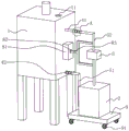
FIG. 1 is an overall schematic view of a cooling apparatus for recycled concrete production in an embodiment of the present application;
FIG. 2 is an enlarged view of a portion of FIG. 1 at A;
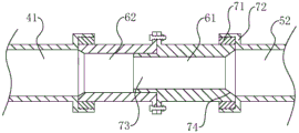
fig. 3 is a structural cross-sectional view of the structure of fig. 2.
Description of reference numerals: 1. a cooling chamber; 11. a feed inlet; 2. a condenser; 3. a water pump; 41. a room water inlet pipe; 42. a chamber water outlet pipe; 51. a water inlet pipe of the device; 52. a water outlet pipe of the device; 61. a first connecting pipe; 62. a second connecting pipe; 63. a flange plate; 71. a first connection block; 72. a second connecting block; 73. inserting a tube; 74. chamfering; 81. a positioning seat; 82. aligning holes; 83. aligning columns; 9. a base; 91. the wheel is moved.
Detailed Description
The present application is described in further detail below with reference to figures 1-3.
The embodiment of the application discloses cooling device for recycled concrete production. Referring to fig. 1, the cooling apparatus for recycled concrete production includes a cooling chamber 1, a condenser 2, a chamber inlet pipe 41, a chamber outlet pipe 42, a machine inlet pipe 51, and a machine outlet pipe 52.
Referring to fig. 1, the cooling chamber 1 has a hollow box shape, and the cooling chamber 1 may be a rectangular box, a circular box, or the like, and in the present embodiment, the cooling chamber 1 has a rectangular box shape. The cavity in the cooling chamber 1 is rectangular cavity form, the top of the cooling chamber 1 is provided with a feed inlet 11, the feed inlet 11 is a round opening, and the recycled concrete aggregate enters the cooling chamber 1 through the feed inlet 11 to be cooled. Be provided with screw thread cooling steel pipe (not shown in the figure) in the cooling chamber 1, the recycled concrete aggregate is through cooling down with spiral cooling steel pipe contact after getting into cooling chamber 1, is spiral helicine spiral cooling steel pipe and can increase its and recycled concrete aggregate's area of contact to improve the cooling effect.
Referring to fig. 1, the chamber inlet pipe 41 and the chamber outlet pipe 42 are both circular pipes, and the diameters of the chamber inlet pipe 41 and the chamber outlet pipe 42 are the same. The chamber water inlet pipe 41 and the chamber water outlet pipe 42 are respectively and fixedly connected to two ends of the threaded cooling steel pipe, so that the chamber water inlet pipe 41 and the chamber water outlet pipe 42 are respectively communicated with the spiral cooling steel pipe, and one ends, far away from the spiral cooling steel pipe, of the chamber water inlet pipe 41 and the chamber water outlet pipe 42 horizontally penetrate through the side wall of the cooling chamber 1 to the outer side of the cooling chamber 1.
Referring to fig. 1, device inlet pipe 51 and device outlet pipe 52 are also circular pipes, the pipe diameter of device inlet pipe 51 is equal to that of device outlet pipe 52, and the pipe diameters of device inlet pipe 51, device outlet pipe 52, chamber inlet pipe 41 and chamber outlet pipe 42 are the same. The device water inlet pipe 51 and the device water outlet pipe 52 are both fixedly connected to the condenser 2, the device water outlet pipe 52 is detachably connected with the chamber water inlet pipe 41, and the device water inlet pipe 51 is detachably connected with the chamber water outlet pipe 42. Wherein, ware outlet pipe 52 is connected with water pump 3, and condenser 2 passes through water pump 3 and goes out condensate pump 3, and the condensate water that pumps passes through ware outlet pipe 52 and room inlet tube 41 in proper order and enters into the spiral cooling steel pipe in cooling chamber 1, and the condensate water is after absorbing the heat in cooling chamber 1, again in proper order through room outlet pipe 42 and the ware inlet tube 51 backward flow condenser 2 to reuse the condensate water. Meanwhile, when the cooling device for recycled concrete production needs to be moved, the condenser 2 and the cooling chamber 1 can be separated by detaching the condenser outlet pipe 52 and the chamber inlet pipe 41 and detaching the chamber outlet pipe 42 and the condenser inlet pipe 51, so that the condition that the condenser 2 and the cooling chamber 1 need to be moved simultaneously is avoided, and the movement of the cooling device for recycled concrete production is facilitated.
Referring to fig. 1 and 2, the device water outlet pipe 52 and the device water inlet pipe 51 are both connected with a first connecting pipe 61, the chamber water inlet pipe 41 and the chamber water outlet pipe 42 are both fixedly connected with a second connecting pipe 62, the first connecting pipe 61 and the second connecting pipe 62 are both circular pipes, and the first connecting pipe 61, the second connecting pipe 62, the device water outlet pipe 52, the device water inlet pipe 51, the outer diameters between the chamber water inlet pipe 41 and the chamber water outlet pipe 42 are consistent, the first connecting pipe 61 and the second connecting pipe 62 are connected with each other through a flange 63, at this time, the first connecting pipe 61 and the second connecting pipe 62 can be separated by separating the flange 63, so that the device water outlet pipe 52 and the chamber water inlet pipe 41, and the device water inlet pipe 51 and the chamber water outlet pipe 42 are detachably connected.
Referring to fig. 1 and 3, the end of the first connection pipe 61 away from the flange 63 and the end of the second connection pipe 62 away from the flange 63 are both sleeved with a first connection block 71, and the ends of the device water inlet pipe 51 and the device water outlet pipe 52 away from the condenser 2 and the outer ends of the chamber water inlet pipe 41 and the chamber water outlet pipe 42 are both sleeved with a second connection block 72. Specifically, the first connecting block 71 is annular, the inner diameter of the first connecting block 71 is equal to the outer diameter of the first connecting pipe 61 and the outer diameter of the second connecting pipe 62, when the first connecting block 71 is sleeved on the first connecting pipe 61 and the second connecting pipe 62, the end face of one end of the first connecting block 71 is flush with the end face of the first connecting pipe 61 or the end face of the second connecting pipe 62, and an external thread is formed on the outer wall of the circumference of the first connecting block 71.
Referring to fig. 1 and 3, the second connection block 72 is in a circular cap shape, the inner diameter of the second connection block 72 is equal to the outer diameters of the device water outlet pipe 52, the device water inlet pipe 51, the chamber water inlet pipe 41 and the chamber water outlet pipe 42, respectively, when the second connection block 72 is sleeved on the device water outlet pipe 52, the device water inlet pipe 51, the chamber water outlet pipe 42 or the chamber water inlet pipe 41, respectively, the inner end surface of the second connection block 72 is flush with the end surface of the pipe, and the inner circumferential wall of the second connection block 72 is provided with internal threads.
Referring to fig. 1 and 3, the first connection block 71 and the second connection block 72 are threadedly connected by external and internal threads, such that the first connection pipe 61 is detachably connected to the device outlet pipe 52 and the device inlet pipe 51, respectively, and the second connection pipe 62 is detachably connected to the chamber inlet pipe 41 and the chamber outlet pipe 42, thereby facilitating the detachment of the first connection pipe 61 or the second connection pipe 62 for maintenance or replacement when a condition requiring maintenance or replacement occurs in the first connection pipe 61 and the second connection pipe 62.
Referring to fig. 3, an insertion tube 73 is integrally connected to an end of the first connection tube 61 facing the second connection tube 62, and the insertion tube 73 is also a circular tube. Specifically, the outer diameter of the insertion tube 73 is equal to the inner diameter of the second connection tube 62, the length of the insertion tube 73 is smaller than that of the second connection tube 62, after the first connection tube 61 and the second connection tube 62 are connected, the insertion tube 73 is inserted into the second connection tube 62, and the outer wall of the insertion tube 73 is attached to the inner wall of the second connection tube 62, so that the sealing area between the first connection tube 61 and the second connection tube 62 is increased, and the sealing performance between the first connection tube 61 and the second connection tube 62 is improved.
Referring to fig. 1 and 3, chamfers 74 are disposed between the inner wall of the device water outlet pipe 52 and the inner wall of the first connecting pipe 61, between the inner wall of the device water inlet pipe 51 and the inner wall of the first connecting pipe 61, between the inner wall of the chamber water inlet pipe 41 and the inner wall of the second connecting pipe 62, and between the inner wall of the chamber water outlet pipe 42 and the inner wall of the second connecting pipe 62, and water flow in the pipes is smoother due to the provision of the chamfers 74.
Referring to fig. 1 and 3, the outer wall of the cooling chamber 1 is provided with a positioning seat 81, the cooling chamber 1 is rectangular, the positioning seat 81, the chamber water inlet pipe 41 and the chamber water outlet pipe 42 are located on the same side wall of the cooling chamber 1, a positioning hole 82 is formed in one surface of the positioning seat 81 departing from the cooling chamber 1, and the positioning hole 82 is a rectangular hole. Correspondingly, the ware outlet pipe 52 is fixed with the counterpoint post 83, and the counterpoint post 83 is rectangular column, and the counterpoint post 83 cooperation counterpoint hole 82 sets up, and the width of counterpoint post 83 corresponds the aperture of counterpoint hole 82 promptly, and when the counterpoint post 83 inserted in the counterpoint hole 82, the axis of first connecting pipe 61 and the axis collineation of second connecting pipe 62, the outer wall of counterpoint post 83 and the laminating of the inner wall of counterpoint hole 82 when the counterpoint post 83 inserted in the counterpoint hole 82. The opening of the alignment hole 82 is a bell mouth, and the alignment post 83 is easy to insert into the alignment hole 82. And the length of the aligning post 83 is greater than that of the insertion tube 73, it is convenient to align the first and second connection pipes 61 and 62 by inserting the aligning post 83 into the aligning hole 82 so that the first and second connection pipes 61 and 62 are connected, thereby facilitating the connection between the device outlet pipe 52 and the chamber inlet pipe 41 and between the device inlet pipe 51 and the chamber outlet pipe 42.
Referring to fig. 1, a base 9 is provided at the bottom of the condenser 2, and the base 9 is in the shape of a rectangular seat. The bottom of the base 9 is provided with a moving wheel 91, so that when the condenser 2 needs to be moved, the condenser 2 can be easily moved by moving the base 9. Further, the moving wheels 91 are universal wheels, so that the flexibility of movement of the base 9 is improved, and further the movement of the condenser 2 is facilitated.
The implementation principle of a cooling device for recycled concrete production of this application embodiment is: when the cooling device for recycled concrete production needs to be moved, the flange plate 63 between the first connecting pipe 61 and the second connecting pipe 62 is separated, so that the condenser outlet pipe 52 and the chamber inlet pipe 41 can be detached, the chamber outlet pipe 42 and the condenser inlet pipe 51 can be detached, the condenser 2 and the cooling chamber 1 can be separated, the condition that the condenser 2 and the cooling chamber 1 need to be moved simultaneously is avoided, and the movement of the cooling device for recycled concrete production is facilitated.
The above embodiments are preferred embodiments of the present application, and the protection scope of the present application is not limited by the above embodiments, so: all equivalent changes made according to the structure, shape and principle of the present application shall be covered by the protection scope of the present application.
Claims (8)
Priority Applications (1)
| Application Number | Priority Date | Filing Date | Title |
|---|---|---|---|
| CN202023102328.4U CN213977458U (en) | 2020-12-19 | 2020-12-19 | A cooling device for recycled concrete production |
Applications Claiming Priority (1)
| Application Number | Priority Date | Filing Date | Title |
|---|---|---|---|
| CN202023102328.4U CN213977458U (en) | 2020-12-19 | 2020-12-19 | A cooling device for recycled concrete production |
Publications (1)
| Publication Number | Publication Date |
|---|---|
| CN213977458U true CN213977458U (en) | 2021-08-17 |
Family
ID=77247369
Family Applications (1)
| Application Number | Title | Priority Date | Filing Date |
|---|---|---|---|
| CN202023102328.4U Expired - Fee Related CN213977458U (en) | 2020-12-19 | 2020-12-19 | A cooling device for recycled concrete production |
Country Status (1)
| Country | Link |
|---|---|
| CN (1) | CN213977458U (en) |
Cited By (1)
| Publication number | Priority date | Publication date | Assignee | Title |
|---|---|---|---|---|
| CN113751113A (en) * | 2021-09-03 | 2021-12-07 | 东莞市建业混凝土有限公司 | Light recycled concrete waste recovery device |
-
2020
- 2020-12-19 CN CN202023102328.4U patent/CN213977458U/en not_active Expired - Fee Related
Cited By (1)
| Publication number | Priority date | Publication date | Assignee | Title |
|---|---|---|---|---|
| CN113751113A (en) * | 2021-09-03 | 2021-12-07 | 东莞市建业混凝土有限公司 | Light recycled concrete waste recovery device |
Similar Documents
| Publication | Publication Date | Title |
|---|---|---|
| CN213977458U (en) | A cooling device for recycled concrete production | |
| CN107856202A (en) | A kind of concrete foamed brick cutter device | |
| CN212524269U (en) | Sealed dust collector of cement encaustic tile waste material crushing process | |
| CN210875102U (en) | Stirring device with filtering structure for processing composite material heat-insulating plate | |
| CN218058660U (en) | A sewage discharge device for a chiller | |
| CN215505768U (en) | Cooling wastewater filtering and circulating device | |
| CN213727713U (en) | Grit splitter of concrete production usefulness | |
| CN207012723U (en) | Waste gas recovery system of polymerizer | |
| CN210544150U (en) | Dust collector is used in haydite proppant production | |
| CN219279984U (en) | Ring type cooling device for preparing pellets | |
| CN216953658U (en) | Cooling device for recycled concrete production | |
| CN220047213U (en) | Novel slag remover | |
| CN223496382U (en) | A furnace slag granulation mechanism | |
| CN214552189U (en) | A dust removal device for producing concrete | |
| CN106830470A (en) | A kind of sewage-treatment plant of strong applicability | |
| CN217415247U (en) | A kind of waste ink recycling and processing device for printing | |
| CN221953529U (en) | Standard brick mould lining board with mould cavity cleaning function | |
| CN206613224U (en) | A kind of acetylene production slurry subsider | |
| CN203833718U (en) | High efficiency energy-saving oxygen increasing device | |
| CN223862789U (en) | Casting sand treatment cooling device | |
| CN218796079U (en) | High-performance concrete raw material crusher | |
| CN220331939U (en) | Vacuum sizing box | |
| CN217748578U (en) | Negative pressure type dust removal device for sand making system | |
| CN205154637U (en) | Water-saving device for vacuum pump | |
| CN219769124U (en) | A convenient disassembly and assembly support adding device for printing models |
Legal Events
| Date | Code | Title | Description |
|---|---|---|---|
| GR01 | Patent grant | ||
| GR01 | Patent grant | ||
| CF01 | Termination of patent right due to non-payment of annual fee | ||
| CF01 | Termination of patent right due to non-payment of annual fee |
Granted publication date: 20210817 |