CN213970093U - Machine part machining device capable of automatically positioning based on computer control - Google Patents
Machine part machining device capable of automatically positioning based on computer control Download PDFInfo
- Publication number
- CN213970093U CN213970093U CN202023284856.6U CN202023284856U CN213970093U CN 213970093 U CN213970093 U CN 213970093U CN 202023284856 U CN202023284856 U CN 202023284856U CN 213970093 U CN213970093 U CN 213970093U
- Authority
- CN
- China
- Prior art keywords
- fixed mounting
- block
- movable block
- limiting rod
- rod
- Prior art date
- Legal status (The legal status is an assumption and is not a legal conclusion. Google has not performed a legal analysis and makes no representation as to the accuracy of the status listed.)
- Active
Links
Images


Landscapes
- Machine Tool Units (AREA)
Abstract
The utility model discloses a but machine parts processingequipment of automatic positioning based on computer control, including fixed mounting panel, bradyseism subassembly, processing piece and first regulation pole, fixed mounting panel's lower extreme is provided with the bradyseism subassembly, the bradyseism subassembly includes fixed mounting seat, first gag lever post, first spring, second gag lever post and second spring, and fixed mounting seat's middle part is provided with first gag lever post, fixed mounting panel's upper surface is provided with the fixed bolster, fixed mounting panel's upper surface is provided with the fixed mounting piece, the middle part of roof is provided with the fixed mounting box, the upper end outside of first regulation pole is provided with the adjustment disk, the lower extreme of first regulation pole is provided with first movable block. This but machine part processingequipment of automatic positioning based on computer control can fix a position it, has avoided long-time the use can lead to the problem that the part damaged, and has improved the device's practical effect.
Description
Technical Field
The utility model relates to a mechanical parts processing correlation technique field specifically is a but mechanical parts processingequipment of automatic positioning based on computer control.
Background
The machining is a process of changing the overall dimension or performance of a workpiece by mechanical equipment, and can be divided into cutting machining, pressure machining and the like according to differences in machining modes, and accurate transmission is required in the machining process, so that a machining device for mechanical parts, which is based on computer control and can automatically position, is particularly important.
The general mechanical part processing device based on computer control is inconvenient to position, can cause part damage after long-time use, and has poor practical effect, so the mechanical part processing device based on computer control and capable of automatically positioning is provided, so that the problems provided in the prior art are solved.
SUMMERY OF THE UTILITY MODEL
An object of the utility model is to provide a but machine part processingequipment based on computer control automatic positioning to solve the general machine part processingequipment based on computer control who proposes in the above-mentioned background art, be not convenient for fix a position, long-time the use can lead to the part to damage, and the not good problem of practical function.
In order to achieve the above object, the utility model provides a following technical scheme: a mechanical part machining device capable of automatically positioning based on computer control comprises a fixed mounting plate, a cushioning component, a machining block and a first adjusting rod, wherein the lower end of the fixed mounting plate is provided with the cushioning component, four corners of the lower end of the cushioning component are provided with fixed support legs, the upper surface of the fixed mounting plate is provided with a fixed support frame, the upper end of the fixed support frame is provided with a top plate, the upper surface of the fixed mounting plate is provided with the fixed mounting block, the machining block is arranged inside the fixed mounting block, the middle part of the top plate is provided with a fixed mounting box, the inside of the fixed mounting box is provided with the first adjusting rod, the outer part of the upper end of the first adjusting rod is provided with an adjusting disc, the right end of the adjusting disc is provided with a second adjusting rod, the rear end of the second adjusting rod is provided with a motor, the lower end of the first adjusting rod is provided with a first movable block, and the lower extreme of first movable block is provided with the drilling head.
Preferably, the bradyseism subassembly includes fixed mounting seat, first gag lever post, first spring, second gag lever post, second spring, second movable block and connecting rod, and fixed mounting seat's middle part is provided with first gag lever post, and the outside of first gag lever post is provided with first spring, and fixed mounting seat's inside is provided with the second gag lever post, and the outer end of second gag lever post is provided with the second spring, and the outside of second gag lever post is provided with the second movable block, and the upper end of second movable block is provided with the connecting rod.
Preferably, the first limiting rod is connected with the fixed mounting seat in a clamping manner, and the first limiting rod forms a sliding structure on the fixed mounting seat through a first spring.
Preferably, the connecting rod and the second movable block form a rotating structure, the second movable block and the second limiting rod are connected in a nested mode, and the second movable block is arranged in a bilateral symmetry mode relative to the central line of the fixed mounting seat.
Preferably, the processing block and the fixed mounting block are connected in a clamping manner, and the processing block forms a sliding structure on the fixed mounting block.
Preferably, the first adjusting rod is connected with the adjusting disc in a threaded mode, and the adjusting disc is connected with the second adjusting rod in a meshed mode.
Compared with the prior art, the beneficial effects of the utility model are that: the machining device for the mechanical part capable of automatically positioning based on computer control can position the machining device, so that the problem that parts are damaged due to long-time use is avoided, and the practical effect of the machining device is improved;
1. the processing block and the fixed mounting block are connected in a clamping manner, so that stable transmission can be facilitated, the processing block is matched to form a sliding structure on the fixed mounting block, the processing block can be limited, processing is facilitated, and the accurate transmission performance of the device is effectively improved;
2. the first limiting rod is arranged to form a clamping type sliding structure on the fixed mounting seat through the first spring, when the fixed mounting plate is subjected to downward vibration force, the damping property is provided for the device, parts are prevented from being damaged and cannot be used, the second movable block arranged at the lower end of the connecting rod is matched to form a nested type sliding structure on the second limiting rod, the fixed mounting plate can be stably mounted on the damping assembly, shaking and inclination are avoided, and the stability and the service life of the device are effectively improved;
3. adjust the pole through adjustment disk and second and adopt the engaged mode to be connected, can drive the synchronous rotation of adjustment disk when opening the motor and rotate the second and adjust the pole, cooperate first regulation pole and adjustment disk to adopt threaded mode to be connected to make first regulation pole can reciprocate, can cooperate the drilling head that first movable block lower extreme set up this moment to carry out the processing operation, the effectual adjustability that improves the device.
Drawings
Fig. 1 is a schematic view of the front cross-sectional structure of the present invention;
FIG. 2 is a schematic side view of the cross-sectional structure of the present invention;
FIG. 3 is a schematic top view of the cross-sectional structure of the present invention;
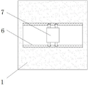
FIG. 4 is a schematic view of the connecting structure of the fixed mounting block and the processing block of the present invention;
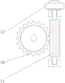
fig. 5 is a schematic view of the cross-sectional structure of the adjusting plate and the second adjusting rod of the present invention.
In the figure: 1. fixing the mounting plate; 2. a cushioning component; 201. fixing the mounting seat; 202. a first limit rod; 203. a first spring; 204. a second limiting rod; 205. a second spring; 206. a second movable block; 207. a connecting rod; 3. fixing the supporting legs; 4. fixing a support frame; 5. a top plate; 6. fixing the mounting block; 7. processing the blocks; 8. fixing the mounting box; 9. a first adjusting lever; 10. an adjusting disk; 11. a second adjusting lever; 12. a motor; 13. a first movable block; 14. and (4) drilling a hole.
Detailed Description
The technical solutions in the embodiments of the present invention will be described clearly and completely with reference to the accompanying drawings in the embodiments of the present invention, and it is obvious that the described embodiments are only some embodiments of the present invention, not all embodiments. Based on the embodiments in the present invention, all other embodiments obtained by a person skilled in the art without creative work belong to the protection scope of the present invention.
Referring to fig. 1-5, the present invention provides a technical solution: a computer control based mechanical part machining device capable of automatically positioning comprises a fixed mounting plate 1, a cushioning component 2, a fixed mounting base 201, a first limiting rod 202, a first spring 203, a second limiting rod 204, a second spring 205, a second movable block 206, a connecting rod 207, a fixed supporting leg 3, a fixed supporting frame 4, a top plate 5, a fixed mounting block 6, a machining block 7, a fixed mounting box 8, a first adjusting rod 9, an adjusting disc 10, a second adjusting rod 11, a motor 12, a first movable block 13 and a drilling head 14, wherein the lower end of the fixed mounting plate 1 is provided with the cushioning component 2, four corners of the lower end of the cushioning component 2 are provided with the fixed supporting leg 3, the cushioning component 2 comprises a fixed mounting base 201, a first limiting rod 202, a first spring 203, a second limiting rod 204, a second spring 205, a second movable block 206 and a connecting rod 207, the middle part of the fixed mounting base is provided with the first limiting rod 202, a first spring 203 is arranged outside the first limiting rod 202, a second limiting rod 204 is arranged inside the fixed mounting seat 201, a second spring 205 is arranged at the outer end of the second limiting rod 204, a second movable block 206 is arranged outside the second limiting rod 204, a connecting rod 207 is arranged at the upper end of the second movable block 206, a fixed support frame 4 is arranged on the upper surface of the fixed mounting plate 1, a top plate 5 is arranged at the upper end of the fixed support frame 4, a fixed mounting block 6 is arranged on the upper surface of the fixed mounting plate 1, a processing block 7 is arranged inside the fixed mounting block 6, a fixed mounting box 8 is arranged in the middle of the top plate 5, a first adjusting rod 9 is arranged inside the fixed mounting box 8, an adjusting disc 10 is arranged outside the upper end of the first adjusting rod 9, a second adjusting rod 11 is arranged at the right end of the adjusting disc 10, and a motor 12 is arranged at the rear end of the second adjusting rod 11, the lower end of the first adjusting rod 9 is provided with a first movable block 13, and the lower end of the first movable block 13 is provided with a drilling head 14.
As shown in fig. 1, 2 and 3, the first limiting rod 202 is connected with the fixed mounting seat 201 in a clamping manner, and the first limiting rod 202 forms a sliding structure on the fixed mounting seat 201 through the first spring 203, so that when the fixed mounting plate 1 is subjected to downward vibration force, the damping performance is provided for the device, damage to parts is avoided, and the device cannot be used, the connecting rod 207 and the second movable block 206 form a rotating structure, the second movable block 206 is connected with the second limiting rod 204 in a nesting manner, and the second movable block 206 is arranged in bilateral symmetry with respect to the central line of the fixed mounting seat 201, so that the fixed mounting plate 1 can be stably mounted on the damping assembly 2, and shaking inclination is avoided.
As shown in fig. 1, 4 and 5, the processing block 7 is connected with the fixed mounting block 6 by means of a clamping, and the processing block 7 forms a sliding structure on the fixed mounting block 6, so that the processing block 7 can be accurately positioned and conveyed, and processing is facilitated, the first adjusting rod 9 is connected with the adjusting disk 10 by means of threads, the adjusting disk 10 is connected with the second adjusting rod 11 by means of meshing, the adjusting disk 10 can be driven to synchronously rotate when the motor 12 is turned on to rotate the second adjusting rod 11, so that the first adjusting rod 9 can move up and down, and at this time, the processing operation can be performed by matching with the drilling head 14 arranged at the lower end of the first movable block 13.
The working principle is as follows: when the machining device for the mechanical part capable of automatically positioning based on computer control is used, firstly, as shown in fig. 1, 4 and 5, the machining block 7 is placed on the fixed mounting block 6, a clamping type sliding structure is formed on the fixed mounting block 6 through the machining block 7, the machining block can be limited when passing through a clamping groove, shaking is avoided, at the moment, a motor 12 arranged at the upper end of the fixed mounting box 8 is opened, the adjusting disc 10 and the second adjusting lever 11 are connected in a meshing mode, the adjusting disc 10 is driven to synchronously rotate when the second adjusting lever 11 can be rotated, the first adjusting lever 9 is matched with the adjusting disc 10 and connected in a threaded mode, so that the first adjusting lever 9 can move up and down, and at the moment, a drilling head 14 arranged at the lower end of the first movable block 13 can be matched for machining operation;
finally, as shown in fig. 1, fig. 2 and fig. 3, when the device is subjected to downward vibration, the first limiting rod 202 is arranged to form a snap-on sliding structure on the fixed mounting seat 201 through the first spring 203, when the fixed mounting plate 1 is subjected to downward vibration force, the device is provided with shock absorption, parts are prevented from being damaged and cannot be used, the second movable block 206 arranged at the lower end of the matching connecting rod 207 forms a nested sliding structure on the second limiting rod 204, the fixed mounting plate 1 can be stably arranged on the shock absorption assembly 2, shaking and inclination are avoided, the fixed support legs 3 arranged in an inclined mode are arranged at four corners of the lower end of the shock absorption assembly 2, the stability of the device can be enhanced, and the whole process of using the mechanical part machining device capable of automatically positioning based on computer control is realized.
Although embodiments of the present invention have been shown and described, it will be appreciated by those skilled in the art that changes, modifications, substitutions and alterations can be made in these embodiments without departing from the principles and spirit of the invention, the scope of which is defined in the appended claims and their equivalents.
Claims (6)
1. The utility model provides a but mechanical parts processingequipment of automatic positioning based on computer control, includes fixed mounting panel (1), bradyseism subassembly (2), processing piece (7) and first regulation pole (9), its characterized in that: the lower end of the fixed mounting plate (1) is provided with a shock absorption component (2), four corners of the lower end of the shock absorption component (2) are provided with fixed support legs (3), the upper surface of the fixed mounting plate (1) is provided with a fixed support frame (4), the upper end of the fixed support frame (4) is provided with a top plate (5), the upper surface of the fixed mounting plate (1) is provided with a fixed mounting block (6), a processing block (7) is arranged inside the fixed mounting block (6), the middle part of the top plate (5) is provided with a fixed mounting box (8), a first adjusting rod (9) is arranged inside the fixed mounting box (8), the outer part of the upper end of the first adjusting rod (9) is provided with an adjusting disc (10), the right end of the adjusting disc (10) is provided with a second adjusting rod (11), and the rear end of the second adjusting rod (11) is provided with a motor (12), the lower end of the first adjusting rod (9) is provided with a first movable block (13), and the lower end of the first movable block (13) is provided with a drilling head (14).
2. The computer-controlled, automatically positionable machine part processing apparatus of claim 1, wherein: the shock absorption assembly (2) comprises a fixed mounting seat (201), a first limiting rod (202), a first spring (203), a second limiting rod (204), a second spring (205), a second movable block (206) and a connecting rod (207), the first limiting rod (202) is arranged in the middle of the fixed mounting seat (201), the first spring (203) is arranged outside the first limiting rod (202), the second limiting rod (204) is arranged inside the fixed mounting seat (201), the second spring (205) is arranged at the outer end of the second limiting rod (204), the second movable block (206) is arranged outside the second limiting rod (204), and the connecting rod (207) is arranged at the upper end of the second movable block (206).
3. The computer-controlled, automatically positionable machine part processing apparatus of claim 2, wherein: the first limiting rod (202) is connected with the fixed mounting seat (201) in a clamping mode, and the first limiting rod (202) forms a sliding structure on the fixed mounting seat (201) through a first spring (203).
4. The computer-controlled, automatically positionable machine part processing apparatus of claim 2, wherein: the connecting rod (207) and the second movable block (206) form a rotating structure, the second movable block (206) and the second limiting rod (204) are connected in a nested mode, and the second movable block (206) is arranged in bilateral symmetry with respect to the center line of the fixed mounting seat (201).
5. The computer-controlled, automatically positionable machine part processing apparatus of claim 1, wherein: the processing block (7) is connected with the fixed mounting block (6) in a clamping mode, and the processing block (7) forms a sliding structure on the fixed mounting block (6).
6. The computer-controlled, automatically positionable machine part processing apparatus of claim 1, wherein: the first adjusting rod (9) is connected with the adjusting disc (10) in a threaded mode, and the adjusting disc (10) is connected with the second adjusting rod (11) in a meshed mode.
Priority Applications (1)
| Application Number | Priority Date | Filing Date | Title |
|---|---|---|---|
| CN202023284856.6U CN213970093U (en) | 2020-12-31 | 2020-12-31 | Machine part machining device capable of automatically positioning based on computer control |
Applications Claiming Priority (1)
| Application Number | Priority Date | Filing Date | Title |
|---|---|---|---|
| CN202023284856.6U CN213970093U (en) | 2020-12-31 | 2020-12-31 | Machine part machining device capable of automatically positioning based on computer control |
Publications (1)
| Publication Number | Publication Date |
|---|---|
| CN213970093U true CN213970093U (en) | 2021-08-17 |
Family
ID=77249189
Family Applications (1)
| Application Number | Title | Priority Date | Filing Date |
|---|---|---|---|
| CN202023284856.6U Active CN213970093U (en) | 2020-12-31 | 2020-12-31 | Machine part machining device capable of automatically positioning based on computer control |
Country Status (1)
| Country | Link |
|---|---|
| CN (1) | CN213970093U (en) |
-
2020
- 2020-12-31 CN CN202023284856.6U patent/CN213970093U/en active Active
Similar Documents
| Publication | Publication Date | Title |
|---|---|---|
| CN103447798B (en) | A kind of device press-fiting engine cylinder cover seat ring | |
| CN110842741A (en) | Polishing equipment is used in timber production | |
| CN213970093U (en) | Machine part machining device capable of automatically positioning based on computer control | |
| CN213969078U (en) | Radial drill convenient to processing | |
| CN115401484B (en) | Avoid detachable lathe duplex position clamping device that loosens | |
| CN216398088U (en) | Vertical double-end drilling machine tool | |
| CN111745431B (en) | Work piece anchor clamps that take precautions against earthquakes | |
| CN109605066B (en) | Automatic positioning device for machining | |
| CN111230193A (en) | Carbon fiber composite board fluting edging device | |
| CN214396313U (en) | Automobile shock absorber ware with adjust suspension function | |
| CN210281204U (en) | Welding device for sound power panel | |
| CN218194801U (en) | Diversified machining anchor clamps | |
| CN217800458U (en) | Lead screw support applied to lead screw transmission | |
| CN217143069U (en) | Gantry single-drive platform driven by high-precision linear motor | |
| CN220144674U (en) | Riveting equipment with shockproof mechanism | |
| CN215846956U (en) | Gantry machining center clamp pressure adjusting device | |
| CN212217824U (en) | Clamping-effect-good positioning device for flywheel machining | |
| CN220805756U (en) | Tapping machine positioner for workpiece machining | |
| CN111203723A (en) | Machining device for mechanical parts | |
| CN212733901U (en) | Automatic change system jar with muscle machine that expands | |
| CN214981492U (en) | Foam mould machine tool with good shockproof capability | |
| CN210254250U (en) | Lathe with shockproof effect | |
| CN219336797U (en) | Surface cutting device for anti-sticking plate blank | |
| CN220019663U (en) | Can improve detection efficiency's chip test jig | |
| CN216229016U (en) | Gearbox backshell frock |
Legal Events
| Date | Code | Title | Description |
|---|---|---|---|
| GR01 | Patent grant | ||
| GR01 | Patent grant |