CN213969537U - Fabric cutting device convenient to clean for spinning - Google Patents
Fabric cutting device convenient to clean for spinning Download PDFInfo
- Publication number
- CN213969537U CN213969537U CN202022294360.0U CN202022294360U CN213969537U CN 213969537 U CN213969537 U CN 213969537U CN 202022294360 U CN202022294360 U CN 202022294360U CN 213969537 U CN213969537 U CN 213969537U
- Authority
- CN
- China
- Prior art keywords
- laser
- push rod
- electric push
- cutting
- fixedly connected
- Prior art date
- Legal status (The legal status is an assumption and is not a legal conclusion. Google has not performed a legal analysis and makes no representation as to the accuracy of the status listed.)
- Active
Links
Images

Abstract
The utility model discloses a surface fabric cutting device is used in weaving convenient to clearance belongs to weaving equipment technical field, including cutting the platform, cut bench side fixed connection fixed column, fixed capital end fixed connection electric putter a, electric putter an top fixed connection horizontal pole, the laser instrument is installed to the horizontal pole bottom. Put the surface fabric earlier on the conveyer belt, adjust the height of laser instrument earlier through electric putter an, after adjusting, the motor drives axis of rotation a and rotates, axis of rotation a drives the conveyer belt and rotates, the conveyer belt drives axis of rotation b and rotates, the motor control conveyer belt passes the surface fabric under to the laser instrument, laser instrument control laser cuts the head and sends laser and cut the surface fabric, the surface fabric that the cutting is good passes through the conveyer belt and passes to the slide on, then get into inside the collecting box, after the surface fabric is cut, electric putter b drives the dead lever and slides from side to side on the slide bar through the slider, the dead lever drives the dust catcher and removes and adsorbs the impurity after cutting.
Description
Technical Field
The utility model relates to a weaving equipment technical field especially relates to a surface fabric cutting device is used in weaving convenient to clearance.
Background
The fabric is used for making the material of the clothes, as one of three elements of the clothes, the fabric can not only explain the style and the characteristics of the clothes, but also directly control the expression effects of the color and the shape of the clothes, the fabric needs to carry out corresponding cutting operation in the processing and production process, and the cutting operation needs to be finished through corresponding cutting devices, but the existing fabric cutting device is relatively lacked, the operation performance is relatively single, certain defects exist during cutting, the traditional fabric cutting device basically cuts through a blade, thus achieving the purpose of cutting, but the fabric cut by the blade easily generates more burrs, the processing quality of the fabric at the later stage is reduced, simultaneously, a large amount of lint is easily generated during cutting, impurities cannot be quickly cleaned, the cutting quality of the device is influenced, the overall flexibility is poor, and the fabric cannot be quickly adjusted according to the actual operation, the practicability of the device is reduced, and the limitation is increased.
Patent No. CN201811220971.1 discloses a fabric cutting device for textile workshops, which comprises a platform, wherein a square through hole is arranged on the platform, sleeves are fixed at two ends of the platform, a collecting box fixed with the sleeves is arranged below the platform, vertical rods are inserted into the upper ends of the sleeves, locking bolts for fastening the vertical rods are arranged on the sleeves, a bearing shaft is fixed between the two vertical rods through fixing bolts, backing plates fixed with the vertical rods are arranged on two sides of the lower end of the bearing shaft, a winding drum is sleeved on the bearing shaft, cloth is wound on the winding drum, a baffle plate and a vertical plate which are oppositely arranged are respectively fixed at the upper end of the platform, the square through hole is arranged between the baffle plate and the vertical plate, a groove is arranged at the back of the baffle plate, a plurality of connecting rods penetrate through the vertical plate, a stop blocks are fixed at the back of the connecting rods, and tension springs sleeved on the connecting rods are fixed between the vertical plate and the stop blocks, the front surface of the connecting rod is fixedly provided with the holding strip, and the upper end of the holding strip is provided with the dovetail groove.
The fabric cutting device of the technology has the following defects: 1. the device is not cleaned after cutting; 2. the condition of burnt limit, deckle edge appears easily, influences the surface fabric quality, for this reason, we provide a surface fabric cutting device for weaving convenient to clearance.
SUMMERY OF THE UTILITY MODEL
The utility model provides a textile fabric cutting device convenient to clean, when cutting fabrics, firstly, the fabrics are put on a conveyor belt, then buttons for controlling an electric push rod a, a laser and a motor on a control switch are opened, firstly, the height of the laser is adjusted through the electric push rod a, the buttons for controlling the electric push rod a on the electric control switch are closed after adjustment, the motor drives a rotating shaft a to rotate, the rotating shaft a drives the conveyor belt to rotate, the conveyor belt drives a rotating shaft b to rotate, the motor controls the conveyor belt to transmit the fabrics to the position under the laser, the laser controls a laser cutting head to emit laser to cut the fabrics, the cut fabrics are transmitted to a slide way through the conveyor belt and then enter into a collecting box, the advantages that the electric push rod a can adjust the cutting height according to the different thicknesses of the fabrics, and the practicability of the device is improved, the laser instrument passes through the laser cutting head and can reach the cutting accuracy to the surface fabric, it is fast, the characteristics that the operation is simple and direct, possess course of working and precision individuation, burnt limit can not appear when cutting simultaneously, unedged condition, close the button of control motor and laser instrument on the control switch after that, after the surface fabric is cut, open the button of electric putter b and dust catcher on the control switch, electric putter b drives the dead lever through the slider and slides from side to side on the slide bar, the dead lever drives the dust catcher and removes and adsorb the impurity after cutting, such benefit is that the dust catcher can collect the impurity after cutting more in the face of, avoid influencing the quality of cutting.
The utility model provides a specific technical scheme as follows:
the utility model provides a textile fabric cutting device convenient to clean, which comprises a cutting table, wherein a fixed column is fixedly connected above the cutting table, the top end of the fixed column is fixedly connected with an electric push rod a, the top end of the electric push rod a is fixedly connected with a cross rod, the bottom of the cross rod is provided with a laser, the bottom of the laser is provided with a laser cutting head, one side of the electric push rod a is fixedly connected with an electric push rod b, one end of the electric push rod b is fixedly connected with a fixed rod, the bottom of the fixed rod can be disassembled and connected with a dust collection box, one side of the dust collection box is fixedly connected with a dust collection pipe, one end of the dust collection pipe is provided with a dust collector, a motor is arranged above the cutting table, one side of the motor is provided with a rotating shaft a, one side of the rotating shaft, a control switch is installed above the cutting table, and the bottom of the cutting table is fixedly connected with a supporting column.
Optionally, a slide bar is arranged inside the cross bar, the outer side wall of the slide bar is connected with a slide block in a sliding manner, and the bottom of the slide block is fixedly connected with a fixed rod.
Optionally, the conveyor belt is connected to the collection box by a chute.
Optionally, the power output end of the motor is connected with the power input end of the rotating shaft a.
Optionally, the control switch is connected with an external power supply through a wire, and an electric power output end of the control switch is connected with electric power input ends of the laser, the electric push rod a, the electric push rod b, the dust collector and the motor.
The utility model has the advantages as follows:
the embodiment of the utility model provides a surface fabric cutting device is used in weaving convenient to clearance:
1. the utility model discloses a cutting platform, electric putter a, the slide bar, the laser instrument, the laser cutting head, including a motor, an axis of rotation a, conveyer belt and axis of rotation b, when cutting the surface fabric, put the surface fabric on the conveyer belt earlier, then open the button that controls electric putter a, laser instrument and motor on the control switch, adjust the height of laser instrument through electric putter a earlier, close the button that controls electric putter a on the electric control switch after adjusting, the motor drives axis of rotation a and rotates, axis of rotation a drives the conveyer belt and rotates, the conveyer belt drives axis of rotation b and rotates, motor control conveyer belt passes the surface fabric under the laser instrument, laser instrument control laser cutting head sends laser and cuts the surface fabric, the surface fabric that cuts passes through the conveyer belt and reaches on the slide, then get into the inside collecting box, such advantage is that electric putter a can adjust the condition of cutting height according to the surface fabric thickness difference, the practicality of the device is improved, the laser can cut the head through the laser and reach cutting accuracy, fast to the surface fabric, the simple and direct characteristics of operation, possess course of working and precision individuation, can not appear the circumstances of burnt limit, deckle edge when cutting simultaneously.
2. The utility model discloses an electric putter a, slide bar, slider and dust catcher, after the face material is cut, open the button of electric putter b and dust catcher on the control switch, electric putter b drives the dead lever horizontal slip on the slide bar through the slider, and the dead lever drives the dust catcher and removes and adsorb the impurity after cutting, and such benefit is that the dust catcher can be collected more in the face of the impurity after cutting, avoids influencing the quality of cutting.
Drawings
In order to more clearly illustrate the technical solutions in the embodiments of the present invention, the drawings needed to be used in the description of the embodiments will be briefly described below, and it is obvious that the drawings in the following description are only some embodiments of the present invention, and it is obvious for those skilled in the art to obtain other drawings without creative efforts.
Fig. 1 is a schematic view of an overall structure of a textile fabric cutting device convenient to clean according to an embodiment of the present invention;
fig. 2 is a schematic structural view of the inside of the sliding rod of the fabric cutting device for textile convenient to clean.
In the figure: 1. a cutting table; 2. a support pillar; 3. fixing a column; 4. an electric push rod a; 5. a cross bar; 6. a slide bar; 7. a laser; 8. laser cutting head; 9. an electric push rod b; 10. fixing the rod; 11. a dust collection box; 12. a dust collection pipe; 13. a vacuum cleaner; 14. a motor; 15. a rotating shaft a; 16. a conveyor belt; 17. a rotating shaft b; 18. a fixed seat; 19. a collection box; 20. a control switch; 21. a slide block.
Detailed Description
In order to make the objects, technical solutions and advantages of the present invention clearer, the present invention will be described in further detail with reference to the accompanying drawings, and it is obvious that the described embodiments are only some embodiments of the present invention, not all embodiments. Based on the embodiments in the present invention, all other embodiments obtained by a person skilled in the art without creative efforts belong to the protection scope of the present invention.
The fabric cutting device for textile convenient to clean according to the embodiment of the present invention will be described in detail with reference to fig. 1 to 2.
Referring to fig. 1 to 2, a textile fabric cutting device convenient to clean provided by an embodiment of the present invention includes a cutting table 1, a fixed column 3 is fixedly connected above the cutting table 1, an electric push rod a4 is fixedly connected at the top end of the fixed column 3, a cross rod 5 is fixedly connected at the top end of the electric push rod a4, a laser 7 is installed at the bottom of the cross rod 5, a laser cutting head 8 is installed at the bottom of the laser 7, an electric push rod b9 is fixedly connected at one side of the electric push rod a4, a fixed rod 10 is fixedly connected at one end of the electric push rod b9, a dust receiving box 11 is detachably connected at the bottom of the fixed rod 10, a dust collecting pipe 12 is fixedly connected at one side of the dust receiving box 11, a dust collector 13 is installed at one end of the dust collecting pipe 12, a motor 14 is installed above the cutting table 1, a rotating shaft a15 is installed at one side of the motor 14, a conveyor belt 16 is installed at one side of the rotating shaft a15, axis of rotation b17 is installed to conveyer belt 16 one side, axis of rotation b17 lateral wall through connection fixing base 18, cut 1 top and install control switch 20, cut 1 bottom fixed connection support column 2 of platform.
Illustratively, the height of the laser 7 is adjusted by the electric push rod a4, the motor 14 drives the rotation shaft a15 to rotate, the rotation shaft a15 drives the conveyor belt 16 to rotate, the conveyor belt 16 drives the rotation shaft b17 to rotate, the motor 14 controls the conveyor belt 16 to convey fabric to the position under the laser 7, the laser 7 controls the laser cutting head 8 to emit laser to cut the fabric, the cut fabric is conveyed to the slide way through the conveyor belt 16 and then enters the collecting box 19, after the fabric is cut, the electric push rod b9 drives the fixing rod 10 to slide left and right on the sliding rod 6 through the sliding block 21, and the fixing rod 10 drives the dust collector 13 to move left and right to adsorb the cut impurities.
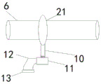
Referring to fig. 1, a sliding rod 6 is installed inside the cross rod 5, the outer side wall of the sliding rod 6 is connected with a sliding block 21 in a sliding manner, and the bottom of the sliding block 21 is fixedly connected with a fixing rod 10.
Illustratively, the electric push rod b9 is convenient to drive the dust collector 13 to move left and right.
Referring to fig. 1, the conveyor belt 16 is connected to a collection bin 17 by a chute.
The cut fabric is collected conveniently.
Referring to fig. 1, the power output end of the motor 14 is connected to the power input end of the rotating shaft a 15.
Illustratively, the motor 14 rotates the rotational shaft a 15.
Referring to fig. 1, the control switch 20 is connected with an external power supply through a wire, and the power output end of the control switch 20 is connected with the power input ends of the laser 7, the electric push rod a4, the electric push rod b9, the dust collector 13 and the motor 14.
Illustratively, the external power supply supplies power to the control switch 20, the laser 7, the electric push rod a4, the electric push rod b9, the vacuum cleaner 13, and the motor 14.
When the fabric cutting device is used, when fabrics are cut, the fabrics are firstly placed on the conveyor belt 16, then buttons for controlling the electric push rod a4 and the laser 7 and the motor 14 on the control switch 20 are turned on, the height of the laser 7 is firstly adjusted through the electric push rod a4, the buttons for controlling the electric push rod a4 on the electric control switch 20 are turned off after adjustment is well done, the motor 14 drives the rotating shaft a15 to rotate, the rotating shaft a15 drives the conveyor belt 16 to rotate, the conveyor belt 16 drives the rotating shaft b17 to rotate, the motor 14 controls the conveyor belt 16 to convey the fabrics to the position under the laser 7, the laser 7 controls the laser cutting head 8 to emit laser to cut the fabrics, the cut fabrics are conveyed to the slide way through the conveyor belt 16 and then enter the collecting box 19, the advantages that the electric push rod a4 can adjust the cutting height according to the different thicknesses of the fabrics, the practicability of the device is improved, and the laser 7 can accurately cut the fabrics through the laser cutting head 8, High speed, simple operation, individualized processing process and precision, no burnt edge and burr during cutting, the buttons on the control switch 20 that control the motor 14 and laser 7 are then turned off, and when the fabric is cut, the button of the electric push rod b9 and the dust collector 13 on the control switch 20 is turned on, the electric push rod b9 drives the fixed rod 10 to slide left and right on the slide rod 6 through the slide block 21, the fixed rod 10 drives the dust collector 13 to move left and right, the dust collector 13 sucks the sucked impurities into the dust collection box 11 through the dust collection pipe 12, the vacuum cleaner 13 has the advantages that the vacuum cleaner 13 can collect cut impurities more completely, the cutting quality is prevented from being affected, and the vacuum cleaner 13 is not limited to be limited to the type DT700 of the electric push rod a4, the type DT300 of the electric push rod b9, the type MD-X1000L of the laser 7, the type DEM-VC10 of the vacuum cleaner 13, the type Y160M1-2 of the motor 14 and the type KG317T of the control switch 20.
The utility model relates to a textile fabric cutting device convenient to clean, which comprises a cutting table 1; 2. a support pillar; 3. fixing a column; 4. an electric push rod a; 5. a cross bar; 6. a slide bar; 7. a laser; 8. laser cutting head; 9. an electric push rod b; 10. fixing the rod; 11. a dust collection box; 12. a dust collection pipe; 13. a vacuum cleaner; 14. a motor; 15. a rotating shaft a; 16. a conveyor belt; 17. a rotating shaft b; 18. a fixed seat; 19. a collection box; 20. a control switch; 21. the slider and the components are all standard parts or components known to those skilled in the art, and the structure and principle of the slider and the components are known to those skilled in the art through technical manuals or through routine experiments.
It is apparent that those skilled in the art can make various changes and modifications to the embodiments of the present invention without departing from the spirit and scope of the embodiments of the present invention. Thus, if such modifications and variations of the embodiments of the present invention fall within the scope of the claims and their equivalents, the present invention is also intended to include such modifications and variations.
Claims (5)
1. A textile fabric cutting device convenient to clean, comprising a cutting table (1), characterized in that the cutting table (1) is fixedly connected with a fixed post (3) above, the top end of the fixed post (3) is fixedly connected with an electric push rod a (4), the top end of the electric push rod a (4) is fixedly connected with a transverse bar (5), a laser is installed at the bottom of the transverse bar (5), a laser cutting head (8) is installed at the bottom of the laser (7), an electric push rod a (4) is fixedly connected with an electric push rod b (9) on one side, the electric push rod b (9) is fixedly connected with a fixed post (10), the fixed post (10) can detachably receive the dust collecting box (11) on one side of which the dust collecting box is fixedly connected with a dust collecting motor (12) 12 is installed at one side of the dust collecting box (11), a rotating shaft a (15) is installed on one side of the motor (14), a conveyor belt (16) is installed on one side of the rotating shaft a (15), a rotating shaft b (17) is installed on one side of the conveyor belt (16), the outer side wall of the rotating shaft b (17) penetrates through the fixed base (18), a control switch (20) is installed above the cutting table (1), and the bottom of the cutting table (1) is fixedly connected with the support post (2).
2. The textile fabric cutting device convenient to clean as claimed in claim 1, characterized in that a slide bar (6) is installed inside the crossbar (5), the outer side wall of the slide bar (6) is slidably connected with a slider (21), and the bottom of the slider (21) is fixedly connected with a fixed link (10).
3. A textile fabric cutting device convenient to clean according to claim 1, characterized in that the conveyor belt (16) and the collecting box (17) are connected through a slide.
4. A textile fabric cutting device convenient to clean as claimed in claim 1, characterized in that the power output of the motor (14) is connected with the power input of the rotating shaft a (15).
5. A textile fabric cutting device convenient to clean according to claim 1, characterized in that the control switch (20) is connected to an external power supply through a lead, and the power output end of the control switch (20) is connected to the power input end of the laser (7), the electric push rod a (4), the electric push rod b (9), the dust collector (13) and the motor (14).
Priority Applications (1)
| Application Number | Priority Date | Filing Date | Title |
|---|---|---|---|
| CN202022294360.0U CN213969537U (en) | 2020-10-15 | 2020-10-15 | Fabric cutting device convenient to clean for spinning |
Applications Claiming Priority (1)
| Application Number | Priority Date | Filing Date | Title |
|---|---|---|---|
| CN202022294360.0U CN213969537U (en) | 2020-10-15 | 2020-10-15 | Fabric cutting device convenient to clean for spinning |
Publications (1)
| Publication Number | Publication Date |
|---|---|
| CN213969537U true CN213969537U (en) | 2021-08-17 |
Family
ID=77256772
Family Applications (1)
| Application Number | Title | Priority Date | Filing Date |
|---|---|---|---|
| CN202022294360.0U Active CN213969537U (en) | 2020-10-15 | 2020-10-15 | Fabric cutting device convenient to clean for spinning |
Country Status (1)
| Country | Link |
|---|---|
| CN (1) | CN213969537U (en) |
-
2020
- 2020-10-15 CN CN202022294360.0U patent/CN213969537U/en active Active
Similar Documents
| Publication | Publication Date | Title |
|---|---|---|
| CN115744425A (en) | Automatic draw non-woven fabrics bead cutter of preventing tangent plane fold | |
| CN111118874B (en) | Edge cutting equipment for non-woven fabric production with high working efficiency | |
| CN210657337U (en) | Novel quick-witted two-sided dust removal of weaving device | |
| CN213969537U (en) | Fabric cutting device convenient to clean for spinning | |
| CN210856508U (en) | Loom with collect waste wire function | |
| CN211804186U (en) | Copper bar cutting device | |
| CN216551296U (en) | Trimming mechanism for loom | |
| CN214300937U (en) | Fluff removing device for textile fabric surface | |
| CN209741543U (en) | Cloth cuts off disc cutter machine | |
| CN213681471U (en) | Fixed-distance cutting device for production of fiber spunlace non-woven fabric | |
| CN211142613U (en) | Multidirectional cutting device of non-woven fabrics | |
| CN209522362U (en) | Fly cutter is crosscutting and the perpendicular all-in-one machine cut of hot knife | |
| CN113102298A (en) | Composite fiber material on-line detection and identification instrument for textile processing | |
| CN215885707U (en) | High-performance fiber material winding device | |
| CN220756673U (en) | A triplet machine for wig | |
| CN216688785U (en) | Textile material cutting device for spinning | |
| CN212560797U (en) | Automatic change textile fabric processing blank holder device | |
| CN218203490U (en) | Shearing device is used in wool production with function is collected to useless hair | |
| CN217026468U (en) | Non-woven fabric production cutting machine | |
| CN219342671U (en) | Waste recycling structure of sheet cutting machine | |
| CN214938678U (en) | Textile cutting device | |
| CN217438468U (en) | Napping machine for napping cloth processing | |
| CN209024759U (en) | One kind is two-sided to cut open seam machine | |
| CN219806114U (en) | Automatic fabric separating and winding device of compounding machine | |
| CN213357889U (en) | Carbon fiber cloth cutting device |
Legal Events
| Date | Code | Title | Description |
|---|---|---|---|
| GR01 | Patent grant | ||
| GR01 | Patent grant |