CN213947314U - Injection molding mouth of a river shearing equipment - Google Patents
Injection molding mouth of a river shearing equipment Download PDFInfo
- Publication number
- CN213947314U CN213947314U CN202022852325.6U CN202022852325U CN213947314U CN 213947314 U CN213947314 U CN 213947314U CN 202022852325 U CN202022852325 U CN 202022852325U CN 213947314 U CN213947314 U CN 213947314U
- Authority
- CN
- China
- Prior art keywords
- cutter
- injection molding
- shearing
- fixed
- assembly
- Prior art date
- Legal status (The legal status is an assumption and is not a legal conclusion. Google has not performed a legal analysis and makes no representation as to the accuracy of the status listed.)
- Active
Links
Images


Landscapes
- Moulds For Moulding Plastics Or The Like (AREA)
Abstract
The utility model relates to an injection molding mouth of a river shearing equipment, include frame, clamping tool, shear unit and compress tightly the subassembly. The clamping jig is fixed on the bottom plate of the frame. The shearing unit is supported by a top plate of the frame and is opposite to the clamping jig. The shearing unit comprises a linear motion element, a mounting substrate and a cutter assembly. The linear motion element is fixed on the top plate to drive the mounting substrate and the cutter assembly to perform displacement motion along the up-down direction. The compressing assembly consists of a top pressing column and an elastic piece. The jacking column is vertically arranged right above the clamping jig and is inserted and fixed on the mounting substrate. The elastic part for directly pressing the injection molding part is fixed on the lower end surface of the top pressing column, and the height position of the bottom surface of the elastic part is not higher than the lowest point of the cutter assembly. The elastic part generates adaptive elastic deformation due to compression to compress the injection molding part, and the injection molding part is prevented from generating position change in subsequent water gap shearing operation.
Description
Technical Field
The utility model belongs to the technical field of the technique of moulding plastics and specifically relates to an injection molding mouth of a river shearing equipment.
Background
In the production process of the existing injection molding product, injection molding can be completed in one step in the same injection mold for injection molding parts capable of being produced in batches, the injection molding products completed in injection molding need to be separated, and because a water gap is reserved for each injection molding part on the injection molding product, the water gap of each injection molding part on the injection molding product needs to be cut off and each injection molding part needs to be separated.
At present, the shearing operation of the injection molding nozzle is usually realized by means of injection molding nozzle shearing equipment. In the prior art, injection molding mouth of a river shearing equipment mainly includes frame, clamping tool and shearing unit. The clamping jig is placed on the bottom plate of the rack. The shearing unit is fixed on the top plate of the frame and is opposite to the clamping jig. The shearing unit comprises a cutter and a cylinder. After the injection molding piece is placed in place on the clamping jig, the cutter moves downwards under the action of the driving force of the cylinder to complete the water gap shearing operation. However, when the injection molding part is subjected to the shearing force, the position of the injection molding part is easily changed relative to the clamping jig, which further affects the shearing accuracy of the nozzle, and even causes the injection molding part to be cut, and thus, a skilled person is urgently needed to solve the above problems.
SUMMERY OF THE UTILITY MODEL
Therefore, in view of the above-mentioned problems and drawbacks, the present invention provides a method for manufacturing a nozzle shearing device for injection molding, which comprises collecting relevant data, evaluating and considering data in multiple ways, and continuously performing experiments and modifications by technical personnel engaged in research and development for many years.
In order to solve the technical problem, the utility model relates to an injection molding mouth of a river shearing equipment, including frame, clamping tool and shearing unit. The frame includes bottom plate, roof and support column. The top plate is horizontally arranged right above the bottom plate. The supporting column is abutted between the bottom plate and the top plate. The clamping jig is fixed on the bottom plate. The shearing unit is supported by the top plate and is opposite to the clamping jig. The shearing unit comprises a linear motion element, a mounting substrate and a cutter assembly. The mounting substrate is arranged right below the top plate and used for mounting and fixing the cutter assembly. The linear motion element is fixed on the top plate to drive the mounting substrate and the cutter assembly to perform displacement motion along the up-down direction. In addition, the shearing unit also comprises a pressing component. The compressing assembly consists of a top pressing column and an elastic piece. The jacking column is vertically arranged right above the clamping jig and is inserted and fixed on the mounting substrate. The elastic part for directly pressing the injection molding part is fixed on the lower end surface of the top pressing column, and the height position of the bottom surface of the elastic part is not higher than the lowest point of the cutter assembly.
As the utility model discloses technical scheme's further improvement, the quantity that compresses tightly the subassembly sets up to 2, symmetrically distributes in the left and right side of cutter unit spare.
As the technical scheme of the utility model is further improved, the shearing unit still includes the direction subassembly. The guide assembly comprises a guide sleeve and a guide rod. The guide sleeve is arranged on the top plate. The guide rod is inserted into the guide sleeve in a freely sliding manner, and the lower end part of the guide rod is fixed on the mounting substrate.
As a further improvement of the technical solution of the present invention, the number of the guiding components is set to 2, and the guiding components are symmetrically arranged on the left and right sides of the cutter component.
As the technical scheme of the utility model is further improved, the preferred cylinder, pneumatic cylinder or linear electric motor of linear motion component.
As the utility model discloses technical scheme's further improvement, cutter unit spare includes blade holder, first cutter, second cutter and fastening screw. The first cutter and the second cutter are oppositely arranged, and the first cutter and the second cutter are detachably fixed with the cutter holder by means of fastening screws.
As the utility model discloses technical scheme's further improvement has seted up first mounting groove, second mounting groove on the blade holder to be used for first cutter of adaptation installation, second cutter respectively. The first mounting groove and the second mounting groove are formed by oppositely inwards recessing the left side wall and the right side wall of the tool apron respectively.
Compare in the injection molding mouth of a river shearing equipment of traditional project organization the utility model discloses an among the technical scheme, its shearing unit additionally has increased and has compressed tightly the subassembly. After the injection molding is placed in place at the clamping tool, the pressing assembly and the cutter assembly synchronously move downwards under the action of the driving force, the elastic part of the pressing assembly is firstly contacted with the injection molding and continuously moves downwards until the cutter assembly is contacted with the injection molding, and in the process, the elastic part is subjected to adaptive elastic deformation due to compression to realize the compression of the injection molding, so that the injection molding is prevented from being subjected to position change in subsequent water gap shearing operation, the phenomenon that the injection molding is cut by the body is avoided, and the final forming quality of the injection molding is ensured.
Drawings
In order to more clearly illustrate the embodiments of the present invention or the technical solutions in the prior art, the drawings used in the description of the embodiments or the prior art will be briefly described below, it is obvious that the drawings in the following description are only some embodiments of the present invention, and for those skilled in the art, other drawings can be obtained according to these drawings without creative efforts.
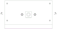
Fig. 1 is a schematic perspective view of an injection molding nozzle shearing apparatus of the present invention.
Fig. 2 is a front view of fig. 1.
Fig. 3 is a top view of fig. 1.
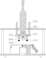
Fig. 4 is a sectional view a-a of fig. 3.
Fig. 5 is the perspective view of the clamping jig in the injection molding nozzle shearing equipment of the present invention.
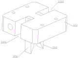
Fig. 6 is a schematic perspective view of a cutter assembly in the shearing apparatus for gate of injection molding of the present invention.
1-a frame; 11-a base plate; 12-a top plate; 13-a support column; 2-clamping a jig; 3-a shearing unit; 31-a cylinder; 32-a mounting substrate; 33-a cutter assembly; 331-a tool apron; 3311-a first mounting groove; 3312-a second mounting groove; 332-a first cutter; 333-a second cutter; 34-a hold down assembly; 341-top pressing column; 342-an elastic member; 35-a guide assembly; 351-a guide sleeve; 352-guide bar.
Detailed Description
In the description of the present invention, it is to be understood that the terms "left", "right", "upper", "lower", "front", "rear", and the like indicate orientations or positional relationships based on those shown in the drawings, and are only for convenience of description and simplification of description, but do not indicate or imply that the device or element referred to must have a specific orientation, be constructed and operated in a specific orientation, and thus, should not be construed as limiting the present invention.
The following will explain the contents of the present invention in detail with reference to the specific embodiments, and fig. 1 shows a schematic perspective view of an injection molding nozzle shearing apparatus of the present invention, which is mainly composed of a frame 1, a clamping fixture 2, a shearing unit 3, and so on. The rack 1 includes a bottom plate 11, a top plate 12, and a support column 13. The top plate 12 is horizontally arranged right above the bottom plate 11. The number of the supporting columns 13 is 4, and the supporting columns are abutted and connected between the bottom plate 11 and the top plate 12. The clamping jig 2 is fixed on the bottom plate 11 and used for loading injection molding parts. The cutter unit 3 is supported by the top plate 12 and is positioned opposite to the chuck 2. The shearing unit 3 includes a cylinder 31, a mounting base plate 32, a cutter assembly 33, and a pressing assembly 34. A mounting base plate 32 is disposed directly below the top plate 12 for mounting a stationary cutter assembly 33. The cylinder body of the air cylinder 31 is fixed to the top plate 12, and the piston rod thereof drives the mounting base plate 32 together with the cutter unit 33 to perform a displacement motion in the up-down direction. The pressing assembly 34 is composed of a pressing column 341 and an elastic member 342. The pressing post 341 is vertically disposed right above the clamping fixture 2, and is inserted and fixed on the mounting substrate 32. The elastic member 342, which directly presses the injection-molded member, is fixed to the lower end surface of the knock-out post 341, and the bottom surface thereof has a height position not higher than the lowest point of the cutter unit 33 (as shown in fig. 2 to 5). Through adopting above-mentioned technical scheme to set up, prevented effectively that the injection molding from taking place the position change in carrying out mouth of a river shearing operation in-process, and then stopped the injection molding body and cut the emergence of hindering the phenomenon, ensured the final shaping quality of injection molding.
The working principle of the injection molding part water gap shearing equipment is as follows: after the injection molding part is loaded in place on the clamping jig 2, the pressing component 34 and the cutter component 33 synchronously move downwards under the action of driving force, the elastic part 342 of the pressing component 34 is firstly contacted with the injection molding part and continues to move downwards until the cutter component 33 is contacted with the injection molding part, in the process, the elastic part 342 is subjected to adaptive elastic deformation due to compression to compress the injection molding part, and meanwhile, the cutter component 33 finishes the cutting operation of a water gap of the injection molding part.
The following two points need to be explained here: 1) the air cylinder 31 can be selected to drive the shearing unit 3, and other linear power elements such as a hydraulic cylinder, a linear motor and the like can be selected according to actual conditions; 2) the elastic member 342 may be a cylindrical spring or an elastic rubber cylinder according to actual conditions.
As a further optimization of the structure of the injection molding nozzle shearing device, the number of the pressing assemblies 34 is preferably set to 2 and symmetrically distributed on the left and right sides of the cutter assembly 33 (as shown in fig. 2). Before the water gap cutting operation is formally executed, the two pressing assemblies 34 are symmetrically abutted against the upper surface of the injection molding part, so that the reliability and the stability of the elastic pressing of the injection molding part are improved.
In order to improve the directionality of the displacement of the cutter assembly 33 in the up-down direction and further ensure accurate cutting of the gate of the injection molded part, the cutting unit 3 is additionally provided with a guide assembly 35 according to actual needs. The guide assembly 35 includes a guide sleeve 351 and a guide rod 352. The guide sleeve 351 is mounted on the top plate 12. The guide rod 352 is slidably inserted into the guide sleeve 351, and its lower end is fixed to the mounting substrate 32 (see fig. 2, 3, and 4).
When the number of the guide assemblies 35 is set to 1 set, the guide assemblies themselves are very susceptible to the action of "lateral force", which causes rapid wear between the guide sleeve 351 and the guide rod 352, thereby severely reducing the service life. In view of this, as a further optimization of the above technical solution, the number of the guide assemblies 35 is preferably set to 2, symmetrically arranged on the left and right sides of the cutter assembly 33 (as shown in fig. 2).
As shown in fig. 6, the cutter assembly 33 includes a cutter holder 331, a first cutter 332, a second cutter 333, and a fastening screw. The first cutter 332 and the second cutter 333 are disposed opposite to each other, and are detachably fixed to the holder 331 by means of a fastening screw. And the tool holder 331 is formed with a first mounting groove 3311 and a second mounting groove 3312 for mounting the first cutter 332 and the second cutter 333 respectively. The first and second mounting grooves 3311, 3312 are formed by opposing inner recesses formed in the left and right sidewalls of the tool holder 331. Through adopting the above technical scheme to set up, after the first cutter 332, the second cutter 333 reached the standard of scrapping through the blade wearing and tearing of its operation of a period of time, do benefit to the staff and carry out and trade new operation.
The previous description of the disclosed embodiments is provided to enable any person skilled in the art to make or use the present invention. Various modifications to these embodiments will be readily apparent to those skilled in the art, and the generic principles defined herein may be applied to other embodiments without departing from the spirit or scope of the invention. Thus, the present invention is not intended to be limited to the embodiments shown herein but is to be accorded the widest scope consistent with the principles and novel features disclosed herein.
Claims (7)
1. A shearing device for a water gap of an injection molding part comprises a rack, a clamping jig and a shearing unit; the rack comprises a bottom plate, a top plate and a support column; the top plate is horizontally arranged right above the bottom plate; the supporting column is abutted between the bottom plate and the top plate; the clamping jig is fixed on the bottom plate; the shearing unit is supported by the top plate and is opposite to the clamping jig; the shearing unit comprises a linear motion element, a mounting substrate and a cutter assembly; the mounting base plate is arranged right below the top plate and used for mounting and fixing the cutter assembly; the linear motion element is fixed on the top plate so as to drive the mounting substrate and the cutter assembly to perform displacement motion along the vertical direction, and the shearing unit is characterized by further comprising a pressing assembly; the pressing assembly consists of a top pressing column and an elastic piece; the jacking column is vertically arranged right above the clamping jig and is inserted and fixed on the mounting substrate; the elastic part for directly pressing the injection molding part is fixed on the lower end surface of the top pressing column, and the height position of the bottom surface of the elastic part is not higher than the lowest point of the cutter component.
2. The injection molding nozzle shearing device of claim 1, wherein the number of the compression assemblies is 2, and the compression assemblies are symmetrically distributed on the left side and the right side of the cutter assembly.
3. The injection molding nozzle shearing apparatus of any one of claims 1-2, wherein said shearing unit further comprises a guide assembly; the guide assembly comprises a guide sleeve and a guide rod; the guide sleeve is arranged on the top plate; the guide rod is inserted into the guide sleeve in a freely sliding manner, and the lower end part of the guide rod is fixed on the mounting substrate.
4. The injection molding nozzle shearing device of claim 3, wherein the number of the guide assemblies is 2, and the guide assemblies are symmetrically arranged on the left side and the right side of the cutter assembly.
5. The injection molding nozzle shearing apparatus of any one of claims 1-2, wherein said linear motion element is a cylinder, a hydraulic cylinder, or a linear motor.
6. The injection molding nozzle shearing apparatus of any one of claims 1-2, wherein the cutter assembly comprises a cutter holder, a first cutter, a second cutter and a fastening screw; the first cutter and the second cutter are oppositely arranged, and the first cutter and the second cutter are detachably fixed with the cutter holder by means of the fastening screw.
7. The injection molding nozzle shearing equipment of claim 6, wherein a first mounting groove and a second mounting groove are formed in the cutter holder and are respectively used for mounting the first cutter and the second cutter in a matching manner; the first mounting groove and the second mounting groove are formed by oppositely and inwards recessing the left side wall and the right side wall of the tool apron respectively.
Priority Applications (1)
| Application Number | Priority Date | Filing Date | Title |
|---|---|---|---|
| CN202022852325.6U CN213947314U (en) | 2020-12-02 | 2020-12-02 | Injection molding mouth of a river shearing equipment |
Applications Claiming Priority (1)
| Application Number | Priority Date | Filing Date | Title |
|---|---|---|---|
| CN202022852325.6U CN213947314U (en) | 2020-12-02 | 2020-12-02 | Injection molding mouth of a river shearing equipment |
Publications (1)
| Publication Number | Publication Date |
|---|---|
| CN213947314U true CN213947314U (en) | 2021-08-13 |
Family
ID=77214924
Family Applications (1)
| Application Number | Title | Priority Date | Filing Date |
|---|---|---|---|
| CN202022852325.6U Active CN213947314U (en) | 2020-12-02 | 2020-12-02 | Injection molding mouth of a river shearing equipment |
Country Status (1)
| Country | Link |
|---|---|
| CN (1) | CN213947314U (en) |
Cited By (1)
| Publication number | Priority date | Publication date | Assignee | Title |
|---|---|---|---|---|
| CN114506028A (en) * | 2021-11-26 | 2022-05-17 | 东莞市达辉精密塑胶科技有限公司 | Full-automatic mouth of a river tool of cutting of injection molding |
-
2020
- 2020-12-02 CN CN202022852325.6U patent/CN213947314U/en active Active
Cited By (1)
| Publication number | Priority date | Publication date | Assignee | Title |
|---|---|---|---|---|
| CN114506028A (en) * | 2021-11-26 | 2022-05-17 | 东莞市达辉精密塑胶科技有限公司 | Full-automatic mouth of a river tool of cutting of injection molding |
Similar Documents
| Publication | Publication Date | Title |
|---|---|---|
| CN211542521U (en) | Die punch device of electronic product | |
| CN213947314U (en) | Injection molding mouth of a river shearing equipment | |
| CN219597862U (en) | Automobile stamping part die | |
| CN217453322U (en) | Automobile mold forming device with edge polishing mechanism | |
| CN113333589B (en) | Automobile fender flanging die and machining method | |
| CN215237252U (en) | Back thimble anti-extrusion deformation die for producing notebook computer shell | |
| CN212822074U (en) | Double-notch cutting device for stamping U-shaped guide groove piece | |
| CN213671449U (en) | Combined stretching die | |
| CN213033435U (en) | Bumper secondary stamping die that buckles | |
| CN114228047A (en) | Injection mold of tubulose cosmetics packaging product | |
| CN212703885U (en) | Pressure forming machine | |
| CN115229045A (en) | Pole piece manufacturing system of SQ filter | |
| CN221415147U (en) | Trimming equipment for mold processing | |
| CN218505276U (en) | Four-point riveting equipment for plastic shell and sleeve | |
| CN217346668U (en) | Automobile plastic product bending die | |
| CN110586768A (en) | Convenient ejecting compression molding mould | |
| CN220005606U (en) | Multi-direction punching and forming integrated die for plate | |
| CN215791114U (en) | Machining die for high-strength compression-resistant draw-bar box | |
| CN213381678U (en) | Door glass run channel cutting device | |
| CN217223111U (en) | Hole flanging die | |
| CN214490880U (en) | Many function combination formula unloading mould | |
| CN221047119U (en) | Pressing forming die | |
| CN216655982U (en) | Side impact driving block and forced reset shared structure | |
| CN221271849U (en) | Bumper upper headlight cleaning cover plate die sinking device | |
| CN213134695U (en) | Auto-parts is apparatus for producing for cut-out press |
Legal Events
| Date | Code | Title | Description |
|---|---|---|---|
| GR01 | Patent grant | ||
| GR01 | Patent grant |