CN213947216U - Automobile air conditioner compressor shell forming equipment - Google Patents
Automobile air conditioner compressor shell forming equipment Download PDFInfo
- Publication number
- CN213947216U CN213947216U CN202022312534.1U CN202022312534U CN213947216U CN 213947216 U CN213947216 U CN 213947216U CN 202022312534 U CN202022312534 U CN 202022312534U CN 213947216 U CN213947216 U CN 213947216U
- Authority
- CN
- China
- Prior art keywords
- mold
- fixedly connected
- injection
- cooling
- air conditioner
- Prior art date
- Legal status (The legal status is an assumption and is not a legal conclusion. Google has not performed a legal analysis and makes no representation as to the accuracy of the status listed.)
- Active
Links
Images


Landscapes
- Moulds For Moulding Plastics Or The Like (AREA)
Abstract
The utility model discloses a vehicle air conditioner compressor casing former relates to vehicle air conditioner compressor technical field, specifically is a vehicle air conditioner compressor casing former, including bottom plate and roof, the top fixed mounting of bottom plate has the pillar, the pillar is inverts the U-shaped, the outside movable mounting on pillar top has the pivot, the conveyer belt has been cup jointed in the outside activity of pivot. This vehicle air conditioner compressor casing former, through setting up the conveyer belt, the same interval position is provided with mold core and heat insulating board on the conveyer belt, set up the baffle in the top of bottom plate simultaneously, utilize telescopic link and injection mold and cooling mold's cooperation, the process of moulding plastics of completion casing that can be convenient, utilize the cooperation of servo motor and conveyer belt simultaneously, take off the casing follow mold core of plastic at the left end of conveyer belt through the manual work, the completion is collected, can effectually prevent that mould self from demoulding the casing and pounding and fall and cause the damage.
Description
Technical Field
The utility model relates to a vehicle air conditioner compressor technical field specifically is a vehicle air conditioner compressor casing former.
Background
The automobile air conditioner compressor is the heart of automobile air conditioner refrigerating system, plays the effect of compression and transport refrigerant steam, and the compressor divide into unchangeable discharge capacity and variable discharge capacity two kinds, according to theory of operation's difference, and air conditioner compressor can divide into the compressor of fixed displacement and variable discharge capacity, and according to the difference of working method, the compressor generally can divide into reciprocating type and rotation type, and common reciprocating compressor has bent axle connecting rod formula and axial piston, and common rotary compressor has rotatory blade formula and vortex formula.
The automobile air-conditioning compressor is mechanical equipment for cooling air by compressing hot air, and in the manufacturing process of an outer shell of the automobile air-conditioning compressor, an injection molding mode is usually utilized.
SUMMERY OF THE UTILITY MODEL
Not enough to prior art, the utility model provides a vehicle air conditioner compressor casing former has solved the problem that proposes in the above-mentioned background art.
In order to achieve the above purpose, the utility model discloses a following technical scheme realizes: a shell forming device of an automobile air conditioner compressor comprises a bottom plate and a top plate, wherein a supporting column is fixedly arranged above the bottom plate and is in an inverted U shape, a rotating shaft is movably arranged at the outer part of the top end of the supporting column, a conveying belt is sleeved outside the rotating shaft, a servo motor is fixedly connected in front of the left side of the conveying belt, two baffle plates are fixedly arranged above the bottom plate, the inner side of each baffle plate is fixedly connected with two telescopic rods which are parallel to each other left and right, an injection mold is fixedly arranged on the inner side of each telescopic rod on the right side, a cooling mold is fixedly connected on the inner side of each telescopic rod on the left side, a cooling liquid pipe is fixedly connected on the outer side of each cooling mold, a cooling liquid circulating pump is fixedly arranged at the bottom end of each cooling liquid pipe, two hydraulic columns are fixedly connected below the top plate, and an injection molding box is fixedly arranged below the two hydraulic columns, the bottom fixedly connected with fixed plate of case four corners moulds plastics, the inside fixed mounting of fixed plate has the spring, the inside fixedly connected with diving board of spring, the below fixedly connected with pipe of moulding plastics of case, the outside fixed mounting of conveyer belt has the heat insulating board, the outside fixedly connected with mold core of heat insulating board.
Optionally, the top of injection mold is equipped with the inside notes liquid hole of straight-through, injection mold's inside is cavity, the inside cavity that is of cooling mold, it is located the injection pipe under to annotate the liquid hole.
Optionally, the distance between the mold cores on the conveyor belt is the same, the size of the mold core is smaller than the hollow size of the injection mold and the cooling mold, and the injection mold and the cooling mold are respectively located outside two continuous mold cores.
Optionally, the thickness reduces gradually around the diving board from top to bottom, two around the diving board top interval value is less than two injection mold's thickness value around.
Optionally, the bottom of four telescopic links is connected with the same hydraulic pump, the case of moulding plastics is located directly over conveyer belt top right-hand member mold core.
The utility model provides a vehicle air conditioner compressor casing former possesses following beneficial effect:
1. this vehicle air conditioner compressor casing former, through setting up the conveyer belt, the same interval position is provided with mold core and heat insulating board on the conveyer belt, set up the baffle in the top of bottom plate simultaneously, utilize telescopic link and injection mold and cooling mold's cooperation, the process of moulding plastics of completion casing that can be convenient, utilize the cooperation of servo motor and conveyer belt simultaneously, can accomplish in proper order through the conveyer belt and mould plastics, cooling, fashioned process, realize the process of continuous quick production, take off the casing follow mold core of plastic at the left end of conveyer belt through the manual work, accomplish and collect, can effectually prevent that mould self from taking off the membrane casing and pounding and fall and cause the damage.
2. This vehicle air conditioner compressor casing former, set up the fixed plate through the four corners at the incasement end of moulding plastics, at the inboard coupling spring of fixed plate, utilize the diving board to install the inboard at the spring, utilize the cooperation of roof and hydraulic pressure post simultaneously, can be at the in-process that the case descends that moulds plastics through hydraulic pressure post control, diving board and injection mold contact from top to bottom, effect through the spring makes two injection mold of diving board decline be in the state of step-up, effectively prevent the mould wearing and tearing, it is not tight to seal, it is not good to cause the lodging effect.
Drawings
FIG. 1 is a schematic structural view of the present invention;
FIG. 2 is a schematic view of the northwest view of the present invention;
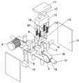
fig. 3 is a schematic exploded view of the present invention.
In the figure: 1. a base plate; 2. a pillar; 3. a rotating shaft; 4. a servo motor; 5. a baffle plate; 6. a telescopic rod; 7. injection molding a mold; 8. cooling the mold; 9. a coolant tube; 10. a coolant circulation pump; 11. a top plate; 12. a hydraulic column; 13. injection molding a box; 14. a spring; 15. a spring plate; 16. a conveyor belt; 17. a mold core; 18. a heat insulation plate; 19. injection molding a tube; 20. and (7) fixing the plate.
Detailed Description
The technical solutions in the embodiments of the present invention will be described clearly and completely with reference to the accompanying drawings in the embodiments of the present invention, and it is obvious that the described embodiments are only some embodiments of the present invention, not all embodiments.
Referring to fig. 1 to 3, the present invention provides a technical solution: a shell forming device of an automobile air conditioner compressor comprises a bottom plate 1 and a top plate 11, wherein a supporting column 2 is fixedly arranged above the bottom plate 1, the supporting column 2 is in an inverted U shape, a rotating shaft 3 is movably arranged outside the top end of the supporting column 2, a conveying belt 16 is movably sleeved outside the rotating shaft 3, a servo motor 4 is fixedly connected in front of the left side of the conveying belt 16, two baffles 5 are fixedly arranged above the bottom plate 1, the inner side of each baffle 5 is fixedly connected with two telescopic rods 6 which are parallel to each other left and right, an injection mold 7 is fixedly arranged on the inner side of the right telescopic rod 6, a cooling mold 8 is fixedly connected on the inner side of the left telescopic rod 6, a cooling liquid pipe 9 is fixedly connected outside the cooling mold 8, a cooling liquid circulating pump 10 is fixedly arranged at the bottom end of the cooling liquid pipe 9, the cooling liquid circulating pump 10 is matched with the cooling liquid pipe 9 to conveniently complete cooling of the cooling mold 8, and cooling in the shell cooling mold 8 is accelerated, so that the formed shell can be conveniently taken out by subsequent manual hand, automatic demoulding is prevented, the shell which is just formed is scratched and is easy to crack, and meanwhile, the cooling is accelerated to play a certain shaping role, two hydraulic columns 12 are fixedly connected below a top plate 11, an injection molding box 13 is fixedly arranged below the two hydraulic columns 12, fixing plates 20 are fixedly connected to the bottoms of four corners of the injection molding box 13, springs 14 are fixedly arranged inside the fixing plates 20, elastic plates 15 are fixedly connected inside the springs 14, the elastic plates 15 play a role in fixing and clamping, the elastic plates 15 enable two injection molds 7 to be tightly attached under the reaction force of the springs 14 and the fixing plates 20 so as to prevent leakage caused by incomplete sealing of the injection molds 7 and influence the forming quality of the shell, injection molding pipes 19 are fixedly connected below the injection molding box 13, heat insulation plates 18 are fixedly arranged outside a conveyor belt 16, and mold cores 17 are fixedly connected outside the heat insulation plates 18, the mold core 17 is mainly matched with the injection mold 7 and the cooling mold 8 to complete the molding process, the effect of facilitating continuous molding is different from that of the traditional left and right mold closing, the heat insulation plate 18 capable of effectively improving the working efficiency plays a role of heat insulation to prevent molten materials from influencing the normal work of the conveyor belt, a liquid injection hole which is communicated with the inside is arranged above the injection mold 7, the inside of the injection mold 7 is hollow, the inside of the cooling mold 8 is hollow, the liquid injection hole is positioned right below the injection pipe 19, the liquid injection hole which is arranged at the upper end of the injection mold 7 is matched with the injection pipe 19 to complete the injection molding work, when the injection mold 7 is closed, the injection pipe 19 is inserted downwards into the liquid injection hole to inject the molten materials in the injection box 13 into the inside of the injection mold 7, the molding work of the shell of the automobile air conditioner compressor is completed through the matching of the injection mold 7 and the mold core 17, the cooling mold 8 plays a role of cooling work after the molding is completed, the distance between the mold cores 17 on the conveyor belt 16 is the same, the size of the mold cores 17 is smaller than the hollow size of the injection mold 7 and the cooling mold 8, the injection mold 7 and the cooling mold 8 are respectively positioned outside the two continuous mold cores 17, the plasticity of the molten liquid is completed through the cooperation of the mold cores 17 and the injection mold 7, then the plasticized shell is cooled through the cooling mold 8 through the cooperation of the servo motor 4 and the conveyor belt 16 so as to be conveniently taken out manually in the next step, the continuous subsection operation of the conveyor belt is favorable for improving the working efficiency, meanwhile, the automatic demolding of the device is prevented, the shell is prevented from being damaged, the front thickness and the back thickness of the elastic plate 15 from top to bottom are gradually reduced, the distance between the top ends of the front elastic plate 15 and the back elastic plate 15 is smaller than the front thickness and the back thickness of the two injection molds 7, the elastic plate 15 mainly plays a role of cooperating with the spring 14, the elastic plate 15 can compress the injection mold 7 to prevent the injection mold 7 from being sealed and untight when the injection box 13 is inserted into the injection hole, cause the incompleteness of moulding, produce the shell of poor quality, same hydraulic pump is connected to the bottom of four telescopic links 6, it is located 16 top right-hand member mold cores 17 directly over to mould plastics case 13, telescopic link 6 is favorable to controlling two injection mold 7 and two cooling mold 8 synchronous motion through same hydraulic pump control system, so that mould or cooling with 17 cooperation completions of mold core, be favorable to improving work efficiency, it is consuming time to reduce processing, effectively prevent that the shell from causing the damage when taking off simultaneously.
To sum up, when the automobile air-conditioning compressor shell forming equipment is used, molten materials are placed inside an injection molding box 13, firstly, an injection mold 7 and a cooling mold 8 are moved inwards to be in a closed state by controlling a telescopic rod 6, then, a cooling liquid circulating pump 10 is started to enable cooling liquid in a cooling liquid pipe 9 to start circulating, the cooling mold 8 is cooled, an injection molding pipe 19 is enabled to be overlapped with an injection molding opening above the injection mold 7 by controlling a hydraulic column 12 to drive the injection molding box 13 to descend, meanwhile, an elastic plate 15 enables the two injection molds 7 to be tightly attached under the reactive force of a spring 14 and a fixed plate 20, then, the injection molding box 13 is controlled to discharge materials, the materials are sent into the injection mold 7 through an injection molding pipe 19, after the molten materials are fixedly formed in the injection mold 7, the telescopic rod 6 is controlled to enable the injection mold 7 and the cooling mold 8 to be separated, and a conveyor belt 16 is driven to move leftwards by a servo motor 4, the mold core 17 is positioned between the two cooling molds 8, the cooling of the outer shell of the mold core 17 is completed by the cooling molds 8, the cooling molds 8 are separated by the telescopic rod 6, and after the conveying belt 16 is driven by the servo motor 4 to move leftwards for a fixed distance, the molded shell is manually taken out from the outer part of the mold core 17.
The above, only be the concrete implementation of the preferred embodiment of the present invention, but the protection scope of the present invention is not limited thereto, and any person skilled in the art is in the technical scope of the present invention, according to the technical solution of the present invention and the utility model, the concept of which is equivalent to replace or change, should be covered within the protection scope of the present invention.
Claims (5)
1. The utility model provides a vehicle air conditioner compressor shell former, includes bottom plate (1) and roof (11), its characterized in that: the upper part of the bottom plate (1) is fixedly provided with a strut (2), the strut (2) is in an inverted U shape, the outer movable mounting at the top end of the strut (2) is provided with a rotating shaft (3), the outer movable mounting of the rotating shaft (3) is sleeved with a conveyor belt (16), the front of the left side of the conveyor belt (16) is fixedly connected with a servo motor (4), the upper part of the bottom plate (1) is fixedly provided with two baffles (5), the inner side of each baffle (5) is fixedly connected with two telescopic rods (6) which are parallel left and right, the inner side of the right side of each telescopic rod (6) is fixedly provided with an injection mold (7), the inner side of each left side of each telescopic rod (6) is fixedly connected with a cooling mold (8), the outer part of each cooling mold (8) is fixedly connected with a cooling liquid pipe (9), and the bottom of each cooling liquid pipe (9) is fixedly provided with a cooling liquid circulating pump (10), two hydraulic pressure posts (12) of below fixedly connected with of roof (11), two the below fixed mounting of hydraulic pressure post (12) has the case (13) of moulding plastics, the bottom fixedly connected with fixed plate (20) in case (13) four corners of moulding plastics, the inside fixed mounting of fixed plate (20) has spring (14), the inside fixedly connected with diving board (15) of spring (14), the below fixedly connected with of case (13) of moulding plastics moulds plastics pipe (19), the outside fixed mounting of conveyer belt (16) has heat insulating board (18), the outside fixedly connected with mold core (17) of heat insulating board (18).
2. The automotive air conditioning compressor shell molding apparatus as claimed in claim 1, wherein: the injection molding machine is characterized in that a liquid injection hole which is communicated with the inside is formed in the upper portion of the injection mold (7), the inside of the injection mold (7) is hollow, the inside of the cooling mold (8) is hollow, and the liquid injection hole is located under the injection molding pipe (19).
3. The automotive air conditioning compressor shell molding apparatus as claimed in claim 1, wherein: the distance between the mold cores (17) on the conveyor belt (16) is the same, the size of each mold core (17) is smaller than the hollow size of the injection mold (7) and the hollow size of the cooling mold (8), and the injection mold (7) and the cooling mold (8) are respectively positioned outside two continuous mold cores (17).
4. The automotive air conditioning compressor shell molding apparatus as claimed in claim 1, wherein: the thickness reduces gradually around shell plate (15) from top to bottom, two around shell plate (15) top interval value is less than the thickness value around two injection mold (7).
5. The automotive air conditioning compressor shell molding apparatus as claimed in claim 1, wherein: the bottom ends of the four telescopic rods (6) are connected with the same hydraulic pump, and the injection molding box (13) is located right above the right end mold core (17) above the conveyor belt (16).
Priority Applications (1)
| Application Number | Priority Date | Filing Date | Title |
|---|---|---|---|
| CN202022312534.1U CN213947216U (en) | 2020-10-16 | 2020-10-16 | Automobile air conditioner compressor shell forming equipment |
Applications Claiming Priority (1)
| Application Number | Priority Date | Filing Date | Title |
|---|---|---|---|
| CN202022312534.1U CN213947216U (en) | 2020-10-16 | 2020-10-16 | Automobile air conditioner compressor shell forming equipment |
Publications (1)
| Publication Number | Publication Date |
|---|---|
| CN213947216U true CN213947216U (en) | 2021-08-13 |
Family
ID=77204887
Family Applications (1)
| Application Number | Title | Priority Date | Filing Date |
|---|---|---|---|
| CN202022312534.1U Active CN213947216U (en) | 2020-10-16 | 2020-10-16 | Automobile air conditioner compressor shell forming equipment |
Country Status (1)
| Country | Link |
|---|---|
| CN (1) | CN213947216U (en) |
Cited By (1)
| Publication number | Priority date | Publication date | Assignee | Title |
|---|---|---|---|---|
| CN114378992A (en) * | 2022-01-12 | 2022-04-22 | 纤镀复材科技(厦门)有限公司 | Equipment for producing carbon fiber rim of bicycle |
-
2020
- 2020-10-16 CN CN202022312534.1U patent/CN213947216U/en active Active
Cited By (1)
| Publication number | Priority date | Publication date | Assignee | Title |
|---|---|---|---|---|
| CN114378992A (en) * | 2022-01-12 | 2022-04-22 | 纤镀复材科技(厦门)有限公司 | Equipment for producing carbon fiber rim of bicycle |
Similar Documents
| Publication | Publication Date | Title |
|---|---|---|
| CN213947216U (en) | Automobile air conditioner compressor shell forming equipment | |
| CN207724716U (en) | A kind of trimming device of injection mold | |
| CN113695531A (en) | Efficient rotary molding machine and using method thereof | |
| CN111844651A (en) | High-efficiency energy-saving plastic part injection molding mold | |
| CN117001955A (en) | Injection mold with high precision machining injection molding efficiency | |
| CN211542145U (en) | Efficient full-automatic cylinder casing drawing of patterns mould | |
| CN216226904U (en) | Precision casting automation line that work efficiency is high | |
| CN214645304U (en) | Prevent injection molding deformation formula injection mold | |
| CN212793010U (en) | Injection molding die for mechanical engineering castings | |
| CN113601783A (en) | Method and process for producing lower cover plate based on mold | |
| CN211640850U (en) | Discharging device for injection molding | |
| CN216607149U (en) | High-efficient rotatory molding machine | |
| CN221028100U (en) | Quartz crucible production drawing of patterns mould | |
| CN217098498U (en) | Pole piece mould convenient to drawing of patterns | |
| CN219543952U (en) | Cooling mechanism for injection mold | |
| CN218611641U (en) | Pouring mold for valve casting | |
| CN216300042U (en) | Demoulding structure of injection moulding mould | |
| CN210061864U (en) | Directional demoulding device for demoulding of injection moulding products | |
| CN116021733B (en) | Quick die replacement device for automobile interior accessory production | |
| CN216941551U (en) | Disposable feeding bottle forming die | |
| CN217395615U (en) | Quick demoulding and ejecting device for automotive interior parts | |
| CN219325442U (en) | Thorough plastic injection mold of drawing of patterns | |
| CN220216646U (en) | Automatic tear wax matrix frock open | |
| CN117001950B (en) | Compressor shell processingequipment | |
| CN215320233U (en) | A casing device of moulding plastics for rifle sight is made |
Legal Events
| Date | Code | Title | Description |
|---|---|---|---|
| GR01 | Patent grant | ||
| GR01 | Patent grant |