CN213942557U - Carbon dioxide trapping and recovering device - Google Patents
Carbon dioxide trapping and recovering device Download PDFInfo
- Publication number
- CN213942557U CN213942557U CN202022030209.6U CN202022030209U CN213942557U CN 213942557 U CN213942557 U CN 213942557U CN 202022030209 U CN202022030209 U CN 202022030209U CN 213942557 U CN213942557 U CN 213942557U
- Authority
- CN
- China
- Prior art keywords
- sliding frame
- carbon dioxide
- spraying
- filtering
- jar
- Prior art date
- Legal status (The legal status is an assumption and is not a legal conclusion. Google has not performed a legal analysis and makes no representation as to the accuracy of the status listed.)
- Active
Links
Images

Abstract
The invention discloses a carbon dioxide capture and recovery device which comprises a spraying structure and a filtering structure, wherein the spraying structure comprises a spraying tank, an air inlet pipe and a spraying plate, the bottom of the outer circumference of the spraying tank is horizontally communicated with the air inlet pipe, the spraying plate is arranged at the top end of the spraying tank, a water outlet is formed in the bottom end of the spraying tank, the upper part of the outer circumference of the spraying tank is horizontally communicated with a guide pipe, the filtering structure comprises a filtering box and a sliding frame, one side end face of the filtering box is communicated with the end part of the guide pipe, the other side end face of the filtering box is communicated with a guide pipe, two sliding grooves are formed in the top face of the filtering box in a vertical penetrating mode, and the sliding frame is vertically and slidably arranged in the sliding grooves. The invention can filter and remove impurities from the waste gas before recovering the carbon dioxide in the industrial waste gas, thereby preventing the dust from blocking the membrane pores and improving the shunting efficiency.
Description
Technical Field
The invention relates to the technical field related to carbon dioxide recovery, in particular to a carbon dioxide capturing and recovering device.
Background
The high-purity CO2 is an important industrial gas, the separated and trapped CO2 can be injected into oil and natural gas fields to improve the oil gas recovery ratio, and can also be widely used for synthesizing organic compounds, manufacturing carbonated beverages and the like to realize resource utilization, the membrane separation method is a main method for separating and recycling the existing main stream, but the existing coal-fired power plant flue gas has high content of solid particle impurities and liquid impurities, so that membrane separation components are easily polluted and even damaged, and the membrane separation efficiency is influenced.
Therefore, a carbon dioxide collecting and recycling device is needed, which can filter and remove impurities from waste gas before recycling carbon dioxide in industrial waste gas, so that the membrane pores are prevented from being blocked by dust, and the shunting efficiency is improved.
Disclosure of Invention
The invention aims to provide a carbon dioxide capture and recovery device, and aims to solve the problems that the existing coal-fired power plant flue gas has high content of solid particle impurities and liquid impurities, and membrane separation components are easily polluted and even damaged, so that the membrane separation efficiency is influenced.
The invention is realized by the following steps: the utility model provides a carbon dioxide entrapment recovery unit, including spraying structure and filtration, spray the structure including spraying the jar, the intake pipe with spout the board, it has the intake pipe to spray jar outer circumference bottom level through connection, and spray the top of jar and install and spout the board, the bottom that sprays the jar link up has seted up the delivery port, and spray jar outer circumference upper portion level through connection has the pipe, filtration includes rose box and sliding frame, a side end face of rose box and the tip through connection of pipe, and the opposite side terminal surface through connection of rose box has the honeycomb duct, two spouts have been seted up to the vertical top surface that runs through on the rose box top surface, and vertical slidable mounting has the sliding frame in the spout.
Furthermore, filter cloth is bonded inside the sliding frame on one side, close to the sliding frame, of the filter box, and filter cotton is bonded inside the sliding frame on one side, far away from the sliding frame, of the filter box.
And then the inside filter cloth that bonds of the smooth frame that is close to one side of smooth frame in the filter box, and the inside filter pulp that bonds of the smooth frame that keeps away from one side of smooth frame in the filter box carries out the multiple operation and filters the edulcoration to promote the convenience of using and filterable validity.
Furthermore, a connecting pipe is vertically arranged on the spraying plate at the top end of the spraying tank in a penetrating mode, and a control valve is arranged on the connecting pipe.
And then install through the top that sprays the jar and spout the board, spout the vertical through-going installation on the board and install the connecting pipe, and install control flap on the connecting pipe to connect outside water pipe and open the valve and wash the smoke and dust in the jar that sprays.
Furthermore, the bottom surface of the spraying tank is uniformly and vertically welded with supporting legs.
And then even vertical welding has the landing leg on the bottom surface through spraying the jar for support connection sprays the jar.
Further, the pillar is vertically welded to the bottom of rose box.
And then the vertical welding in bottom through the rose box has the pillar for the support is connected the rose box.
Compared with the prior art, the invention has the beneficial effects that: the invention
When carrying out the smoke and dust and retrieving, through in the intake pipe with the leading-in spraying jar of smoke and dust air, then utilize the top of spraying the jar to install and spout the board, spout vertical link up on the board and install the connecting pipe, and install control flap on the connecting pipe, thereby connect outside water pipe and open the valve and wash the smoke and dust in the jar that sprays, then the flue gas is guided to the filter box in the pipe, thereby utilize the inside bonding of the sliding frame that is close to one side of sliding frame in the filter box to have the filter cloth, and the inside bonding of sliding frame that keeps away from one side of sliding frame in the filter box has the filter pulp, carry out the multiple operation and filter the edulcoration, thereby promote the convenience of using and filterable validity, the flue gas flows out from the honeycomb duct after filtering, and then can filter the edulcoration to waste gas before the recovery of carbon dioxide in the industrial waste gas, thereby avoid the dust to block up the membrane hole, improve the efficiency of reposition of redundant personnel.
Drawings
In order to more clearly illustrate the technical solutions of the embodiments of the present invention, the drawings that are required to be used in the embodiments will be briefly described below, it should be understood that the following drawings only illustrate some embodiments of the present invention and therefore should not be considered as limiting the scope, and for those skilled in the art, other related drawings can be obtained according to the drawings without inventive efforts.
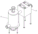
FIG. 1 is a schematic view of the overall structure of the present invention;
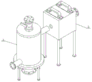
FIG. 2 is a schematic view of an exploded structure of the present invention;
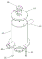
FIG. 3 is a schematic structural diagram of a spray structure in an embodiment of the invention;
fig. 4 is a schematic structural view of a filter structure in an embodiment of the present invention.
In the figure: 1. a spraying structure; 11. a spray tank; 12. an air inlet pipe; 13. spraying a plate; 14. a connecting pipe; 15. a water outlet; 16. a support leg; 17. a conduit; 2. a filter structure; 21. a filter box; 22. a chute; 23. a sliding frame; 24. a filter cloth; 25. filtering cotton; 26. a pillar; 27. and a flow guide pipe.
Detailed Description
In order to make the objects, technical solutions and advantages of the embodiments of the present invention more apparent, the technical solutions of the embodiments of the present invention will be described clearly and completely with reference to the accompanying drawings of the embodiments of the present invention, and it is obvious that the described embodiments are some, but not all embodiments of the present invention. All other embodiments, which can be obtained by a person skilled in the art without any inventive step based on the embodiments of the present invention, are within the scope of the present invention. Thus, the following detailed description of the embodiments of the present invention, presented in the figures, is not intended to limit the scope of the invention, as claimed, but is merely representative of selected embodiments of the invention. All other embodiments, which can be obtained by a person skilled in the art without any inventive step based on the embodiments of the present invention, are within the scope of the present invention.
Referring to fig. 1-4, a carbon dioxide collecting and recycling device comprises a spraying structure 1 and a filtering structure 2, wherein the spraying structure 1 comprises a spraying tank 11, an air inlet pipe 12 and a spraying plate 13, the bottom of the outer circumference of the spraying tank 11 is horizontally connected with the air inlet pipe 12 in a through manner, the top end of the spraying tank 11 is provided with the spraying plate 13, the bottom end of the spraying tank 11 is provided with a water outlet in a through manner, the upper part of the outer circumference of the spraying tank 11 is horizontally connected with a conduit 17 in a through manner, the filtering structure 2 comprises a filtering box 21 and a sliding frame 23, one side end surface of the filtering box 21 is connected with the end part of the conduit 17 in a through manner, the other side end surface of the filtering box 21 is connected with a flow guide pipe 27 in a through manner, the top surface of the filtering box 21 is vertically provided with two sliding grooves 22 in a through manner, the sliding frame 23 is vertically slidably mounted in the sliding manner, when the carbon dioxide collecting and recycling device is used for collecting and recycling smoke dust, smoke air is introduced into the air inlet pipe 12 in the spraying tank 11, then install on the top of utilizing spraying jar 11 and spout board 13, spout the vertical through-mounting on board 13 and install connecting pipe 14, and install control valve on the connecting pipe 14, thereby connect outside water pipe and open the valve and wash the smoke and dust in spraying jar 11, then the flue gas is guided to the rose box 21 from pipe 17, thereby utilize the inside filter cloth 24 that bonds of the smooth frame 23 that is close to one side of smooth frame 23 in the rose box 21, and the smooth frame 23 inside bonding of one side of keeping away from smooth frame 23 in the rose box 21 has filter pulp 25, carry out the multiple operation and filter the edulcoration, thereby promote the convenience of using and filterable validity, the flue gas flows out from honeycomb duct 27 after filtering, and then can filter the edulcoration to waste gas before the recovery of carbon dioxide in the industrial waste gas, thereby avoid the dust to block up the membrane pore, improve the efficiency of reposition of redundant personnel.
Referring to fig. 4, a filter cloth 24 is bonded inside the sliding frame 23 on the side of the filter box 21 close to the sliding frame 23, a filter cotton 25 is bonded inside the sliding frame 23 on the side of the filter box 21 far from the sliding frame 23, the filter cloth 24 is bonded inside the sliding frame 23 on the side of the filter box 21 close to the sliding frame 23, and the filter cotton 25 is bonded inside the sliding frame 23 on the side of the filter box 21 far from the sliding frame 23, so that multiple-process filtration and impurity removal are performed, and convenience in use and effectiveness of filtration are improved.
Referring to fig. 3, a connecting pipe 14 is vertically installed on a spraying plate 13 at the top end of the spraying tank 11 in a penetrating manner, a control valve is installed on the connecting pipe 14, the spraying plate 13 is installed at the top end of the spraying tank 11, the connecting pipe 14 is vertically installed on the spraying plate 13 in a penetrating manner, and the control valve is installed on the connecting pipe 14, so that an external water pipe is connected to open the valve to flush the smoke in the spraying tank 11.
Referring to fig. 3, the bottom surface of the spray tank 11 is uniformly and vertically welded with the support legs 16, and the support legs 16 are uniformly and vertically welded on the bottom surface of the spray tank 11 for supporting and connecting the spray tank 11.
Referring to fig. 3, a pillar 26 is vertically welded to the bottom end of the filter box 21, and the pillar 26 is vertically welded to the bottom end of the filter box 21 for supporting and connecting the filter box 21.
The working principle is as follows: when the device is used, smoke air is guided into the air inlet pipe 12 in the spraying tank 11, then the spraying plate 13 is installed at the top end of the spraying tank 11, the connecting pipe 14 is vertically installed on the spraying plate 13 in a penetrating manner, the control valve is installed on the connecting pipe 14, so that the smoke in the spraying tank 11 is washed by opening the valve through the external water pipe, then the smoke is guided into the filter box 21 from the guide pipe 17, the filter cloth 24 is adhered inside the sliding frame 23 on one side of the filter box 21 close to the sliding frame 23, the filter cotton 25 is adhered inside the sliding frame 23 on one side of the filter box 21 far away from the sliding frame 23, multi-process filtering and impurity removing are carried out, the use convenience and the filtering effectiveness are improved, the filtered smoke flows out from the guide pipe 27, the waste gas can be filtered and impurity removed before the carbon dioxide in the industrial waste gas is recovered, and the film holes are prevented from being blocked by the dust, the efficiency of reposition of redundant personnel is improved.
The device obtained by the design can basically meet the requirements of filtering and removing impurities from the waste gas before recovering the carbon dioxide in the industrial waste gas, thereby preventing dust from blocking membrane pores and improving the shunting efficiency.
The above description is only a preferred embodiment of the present invention and is not intended to limit the present invention, and various modifications and changes may be made by those skilled in the art. Any modification, equivalent replacement, or improvement made within the spirit and principle of the present invention should be included in the protection scope of the present invention.
Claims (5)
1. A carbon dioxide entrapment recovery unit, includes sprays structure (1) and filtration (2), its characterized in that: spray structure (1) including spraying jar (11), intake pipe (12) and spout board (13), it has intake pipe (12) to spray outer circumference bottom level through connection of jar (11), and sprays the top of jar (11) and install spout board (13), the bottom that sprays jar (11) link up has seted up the delivery port, and sprays jar (11) outer circumference upper portion level through connection and have pipe (17), filtration (2) are including rose box (21) and sliding frame (23), a lateral surface of rose box (21) and the tip through connection of pipe (17), and the opposite side terminal surface through connection of rose box (21) has honeycomb duct (27), two spout (22) have been seted up to the vertical top surface that runs through on rose box (21) top surface, and vertical slidable mounting has sliding frame (23) in spout (22).
2. The carbon dioxide capturing and recycling device according to claim 1, characterized in that the inside of the sliding frame (23) on the side of the filtering box (21) close to the sliding frame (23) is bonded with a filtering cloth (24), and the inside of the sliding frame (23) on the side of the filtering box (21) far from the sliding frame (23) is bonded with a filtering cotton (25).
3. The carbon dioxide capturing and recycling device according to claim 1, characterized in that a connecting pipe (14) is vertically installed on the spray plate (13) at the top end of the spray tank (11) in a penetrating manner, and a control valve is installed on the connecting pipe (14).
4. The carbon dioxide capturing and recycling device according to claim 1, characterized in that the bottom surface of the spray tank (11) is welded with legs (16) vertically and uniformly.
5. The carbon dioxide capturing and recycling device as recited in claim 1, characterized in that a pillar (26) is welded vertically to the bottom end of the filter box (21).
Priority Applications (1)
| Application Number | Priority Date | Filing Date | Title |
|---|---|---|---|
| CN202022030209.6U CN213942557U (en) | 2020-09-16 | 2020-09-16 | Carbon dioxide trapping and recovering device |
Applications Claiming Priority (1)
| Application Number | Priority Date | Filing Date | Title |
|---|---|---|---|
| CN202022030209.6U CN213942557U (en) | 2020-09-16 | 2020-09-16 | Carbon dioxide trapping and recovering device |
Publications (1)
| Publication Number | Publication Date |
|---|---|
| CN213942557U true CN213942557U (en) | 2021-08-13 |
Family
ID=77201498
Family Applications (1)
| Application Number | Title | Priority Date | Filing Date |
|---|---|---|---|
| CN202022030209.6U Active CN213942557U (en) | 2020-09-16 | 2020-09-16 | Carbon dioxide trapping and recovering device |
Country Status (1)
| Country | Link |
|---|---|
| CN (1) | CN213942557U (en) |
Cited By (2)
| Publication number | Priority date | Publication date | Assignee | Title |
|---|---|---|---|---|
| CN115155292A (en) * | 2022-07-29 | 2022-10-11 | 北京石大油源科技开发有限公司 | Efficient capturing method and device for high-concentration carbon dioxide |
| CN115178056A (en) * | 2022-07-29 | 2022-10-14 | 北京石大油源科技开发有限公司 | Efficient capturing method and device for medium and high-concentration carbon dioxide |
-
2020
- 2020-09-16 CN CN202022030209.6U patent/CN213942557U/en active Active
Cited By (2)
| Publication number | Priority date | Publication date | Assignee | Title |
|---|---|---|---|---|
| CN115155292A (en) * | 2022-07-29 | 2022-10-11 | 北京石大油源科技开发有限公司 | Efficient capturing method and device for high-concentration carbon dioxide |
| CN115178056A (en) * | 2022-07-29 | 2022-10-14 | 北京石大油源科技开发有限公司 | Efficient capturing method and device for medium and high-concentration carbon dioxide |
Similar Documents
| Publication | Publication Date | Title |
|---|---|---|
| CN213942557U (en) | Carbon dioxide trapping and recovering device | |
| CN201286997Y (en) | Bag type filter device | |
| CN103949100A (en) | Ceramic filter apparatus for separating magnesium hydrate solution, and process thereof | |
| CN105031994A (en) | Novel rain filter | |
| CN212701174U (en) | Dust collector for mining | |
| CN203329454U (en) | Ceramic filter device for separating magnesium hydroxide solution | |
| CN202070257U (en) | Air filtering absorber and water tank adopting same | |
| CN206841039U (en) | A kind of slabstone engraving machine base with dedusting function | |
| CN200977523Y (en) | Multi-stage oil mist purifying collector | |
| CN105217922A (en) | A kind of mud quick dewatering drying device | |
| CN205549772U (en) | Totally closed high filter press cloth candle filter | |
| CN201175610Y (en) | Inter-filter type filter | |
| CN209596720U (en) | A kind of sewage filter device | |
| CN215138268U (en) | High-efficient safe gas-liquid separation jar | |
| CN215469896U (en) | Oil mist dust collecting device for machine tool | |
| CN215539427U (en) | Air purification device for waste plastic cracking recovery plant | |
| CN213823833U (en) | Novel hydraulic punching solid-liquid-gas separator | |
| CN216518123U (en) | Blowout preventer for underground coal mine drainage and drilling construction | |
| CN218459025U (en) | Environment-friendly flue gas dust collecting equipment | |
| CN211098324U (en) | Dewatering and demisting composite device | |
| CN216171090U (en) | Environment-friendly efficient asphalt waste gas purification system | |
| CN214360588U (en) | Multifunctional vacuum liquid collector | |
| CN218924186U (en) | Dedusting and filtering device of Raymond mill | |
| CN211963294U (en) | Drilling fluid filter equipment | |
| CN210448519U (en) | Environmental protection gas wash tower |
Legal Events
| Date | Code | Title | Description |
|---|---|---|---|
| GR01 | Patent grant | ||
| GR01 | Patent grant |