CN213938698U - Power amplifier easy to dissipate heat - Google Patents
Power amplifier easy to dissipate heat Download PDFInfo
- Publication number
- CN213938698U CN213938698U CN202023173987.7U CN202023173987U CN213938698U CN 213938698 U CN213938698 U CN 213938698U CN 202023173987 U CN202023173987 U CN 202023173987U CN 213938698 U CN213938698 U CN 213938698U
- Authority
- CN
- China
- Prior art keywords
- control circuit
- main body
- heat dissipation
- device main
- power amplifier
- Prior art date
- Legal status (The legal status is an assumption and is not a legal conclusion. Google has not performed a legal analysis and makes no representation as to the accuracy of the status listed.)
- Active
Links
Images


Landscapes
- Cooling Or The Like Of Electrical Apparatus (AREA)
Abstract
The utility model relates to a power amplifier technical field specifically is an easy heat dissipation power amplifier, the device comprises a device main body, install control circuit, inductor, radiator fan, first magnetism in the device main body in proper order and inhale groove, second magnetism and inhale groove, spout, control button and display screen, fixed mounting has the fin on control circuit's the surface, install device sliding closure, venthole, inlet port and fixed column in the spout in proper order. The utility model has the advantages that: the problem that power is increased due to long-time operation of the fan, so that hidden danger exists is solved through the matched arrangement of the control circuit, the inductor, the cooling fan and the cooling fins; inhale the cooperation setting in groove, spout, device sliding closure and fixed column through first magnetism, second magnetism, increased the detachability of device, solved because the device is mostly an organic whole, it is very inconvenient to clear up the dismantlement to the device, influences the problem of efficiency.
Description
Technical Field
The utility model relates to a power amplifier technical field, especially an easy heat dissipation power amplifier.
Background
A power amplifier refers to an amplifier that can generate maximum power output to drive a certain load under a given distortion ratio. The power amplifier plays a role of 'organization and coordination' in the whole sound system, and governs to some extent whether the whole system can provide good sound quality output.
The existing power amplifier easy to dissipate heat has the following disadvantages:
1. most of existing power amplifiers easy to dissipate heat adopt fans for heat dissipation, and long-time operation of the fans can also cause power increase, so that hidden danger exists;
2. current easy heat dissipation power amplifier, the device is mostly an organic whole, and it is very inconvenient to clear up the dismantlement to the device, influences efficiency.
SUMMERY OF THE UTILITY MODEL
The utility model aims to overcome the defects of the prior art, improve the heat dissipation function of the device, and prevent the problem of hidden danger because the power is increased due to the heat dissipation of most fans adopted and the long-time operation of the fans; the structure of the device is changed, and the problems that the device is inconvenient to clean and disassemble and the efficiency is influenced because the device is mostly integrated are prevented.
The purpose of the utility model is realized through the following technical scheme: an easy-heat-dissipation power amplifier comprises a device main body, wherein a control circuit is fixedly installed inside the device main body, an inductor is fixedly installed inside the device main body, a heat-dissipation fan is fixedly installed inside the device main body, a first magnetic absorption groove is formed in the upper surface of the device main body, a second magnetic absorption groove is formed in one side of the device main body, a sliding groove is formed in one side of the device main body, a control button is fixedly installed on the outer surface of the device main body, and a display screen is formed in the outer surface of the device main body;
the air inlet device is characterized in that a radiating fin is fixedly mounted on the outer surface of the control circuit, a device sliding cover is movably mounted inside the sliding groove, an air outlet hole is formed in one side of the device sliding cover, an air inlet hole is formed in the other side of the device sliding cover, and a fixing column is fixedly mounted inside the device sliding cover.
Optionally, the control circuit is electrically connected with the control button, and the control circuit is electrically connected with the display screen, so that the device is convenient to operate.
Optionally, the control circuit is provided with a receiver adapted to the sensor and connected to the sensor, and is electrically connected to the cooling fan, so that the cooling fan is conveniently controlled.
Optionally, the inductor is a temperature sensor, the number of inductors is two, and evenly distributed in control circuit's both sides, conveniently to the real-time supervision and the transmission of temperature in the device.
Optionally, the number of the heat dissipation fans is two, the magnets are fixedly installed in the first magnetic attraction grooves, and the magnets matched with the magnets in the first magnetic attraction grooves are arranged inside the sliding covers of the device, so that the device is conveniently fixed.
Optionally, the inside fixed mounting in second magnetism suction groove has magnet, the inside of fixed column is provided with the magnet with the inside magnet looks adaptation in second magnetism suction groove, conveniently installs the device.
Optionally, the number of the chutes is two, and the chutes are distributed on two sides of the device main body, the number of the radiating fins is five, and the radiating fins are uniformly distributed on the outer surface of the control circuit, so that the control circuit is convenient to radiate.
Optionally, the number of the air outlet holes is set according to the size of the device sliding cover, and the number of the air inlet holes is set according to the size of the device sliding cover, so that the device is convenient to dissipate heat.
The utility model has the advantages of it is following:
1. the power amplifier with easy heat dissipation is characterized in that a control circuit is fixedly arranged in a device main body, an inductor is fixedly arranged in the device main body, a heat dissipation fan is fixedly arranged in the device main body, heat dissipation fins are fixedly arranged on the outer surface of the control circuit, an air outlet hole is formed in one side of a device sliding cover, an air inlet hole is formed in the other side of the device sliding cover, a receiver matched with the inductor is arranged in the control circuit and is connected with the inductor, the control circuit is electrically connected with the heat dissipation fan, the inductor is a temperature inductor, the number of the inductors is two and is uniformly distributed on two sides of the control circuit, the number of the heat dissipation fans is two, the number of the heat dissipation fins is five, the heat dissipation fins are uniformly distributed on the outer surface of the control circuit, when the device runs, the heat dissipation is preferentially carried out on the device through the heat dissipation fins on the control circuit, and the temperature in the device is detected through the inductor, real-time transmission to control circuit in, when the temperature rose to the certain limit in the device, the fin can't satisfy the heat dissipation of device this moment, start radiator fan through inductor control circuit, the temperature reduces to the certain limit in the device, closing radiator fan through inductor control circuit, it is better easier to make the radiating effect of device like this, and can not cause the hidden danger owing to radiator fan's long-time work, current easy heat dissipation power amplifier has been solved, the heat dissipation of the fan of most adoption, and long-time operation of fan also can lead to power increase, thereby there is the problem of hidden danger.
2. The power amplifier with the easy heat dissipation function is characterized in that a first magnetic attraction groove is formed in the upper surface of a device main body, a second magnetic attraction groove is formed in one side of the device main body, a sliding groove is formed in one side of the device main body, a device sliding cover is movably arranged in the sliding groove, a fixed column is fixedly arranged in the device sliding cover, magnets are fixedly arranged in the first magnetic attraction groove, magnets matched with the magnets in the first magnetic attraction groove are arranged in the device sliding cover, magnets are fixedly arranged in the second magnetic attraction groove, magnets matched with the magnets in the second magnetic attraction groove are arranged in the fixed column, the number of the sliding grooves is two, the sliding grooves are distributed on two sides of the device main body, when the device needs to be disassembled and cleaned, the fixed column is separated from the inside of the second magnetic attraction groove by applying force to the device sliding cover, the device sliding cover is moved along the sliding grooves, and the device sliding cover is separated from the device main body, carry out the clearance to the device, solved current easy heat dissipation power amplifier, the device is mostly an organic whole, and it is very inconvenient to clear up the dismantlement to the device, influences the problem of efficiency.
Drawings
Fig. 1 is a schematic view of a first view structure of the present invention;
fig. 2 is a schematic view of a second perspective structure of the present invention;
fig. 3 is a schematic view of a third view structure according to the present invention.
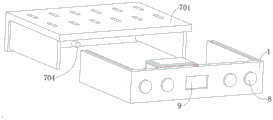
In the figure: 1-device body, 2-control circuit, 201-radiating fin, 3-inductor, 4-radiating fan, 5-first magnetic absorption groove, 6-second magnetic absorption groove, 7-sliding groove, 701-device sliding cover, 702-air outlet, 703-air inlet, 704-fixed column, 8-control button and 9-display screen.
Detailed Description
The invention will be further described with reference to the accompanying drawings, but the scope of the invention is not limited to the following description.
As shown in fig. 1 to 3, the utility model provides an easy-to-radiate power amplifier, including a device main body 1, a control circuit 2 is fixedly installed in the interior of the device main body 1, an inductor 3 is fixedly installed in the interior of the device main body 1, a radiating fan 4 is fixedly installed in the interior of the device main body 1, a first magnetic absorption groove 5 is opened on the upper surface of the device main body 1, a second magnetic absorption groove 6 is opened on one side of the device main body 1, a sliding groove 7 is opened on one side of the device main body 1, a control button 8 is fixedly installed on the outer surface of the device main body 1, and a display screen 9 is opened on the outer surface of the device main body 1;
the outer surface of the control circuit 2 is fixedly provided with a radiating fin 201, the inside of the sliding chute 7 is movably provided with a device sliding cover 701, one side of the device sliding cover 701 is provided with an air outlet hole 702, the other side of the device sliding cover 701 is provided with an air inlet hole 703, and the inside of the device sliding cover 701 is fixedly provided with a fixed column 704.
As an optimal technical solution of the utility model: the control circuit 2 is electrically connected with the control button 8, the control circuit 2 is electrically connected with the display screen 9, the control circuit 2 is internally provided with a receiver matched with the inductor 3 and connected with the inductor, the control circuit 2 is electrically connected with the heat dissipation fan 4, the inductor 3 is a temperature inductor, the number of the inductors is two and is uniformly distributed on two sides of the control circuit 2, the number of the heat dissipation fan 4 is two, the magnet is fixedly arranged in the first magnetic attraction groove 5, the magnet matched with the magnet in the first magnetic attraction groove 5 is arranged in the device sliding cover 701, the magnet is fixedly arranged in the second magnetic attraction groove 6, the magnet matched with the magnet in the second magnetic attraction groove 6 is arranged in the fixed column 704, the number of the sliding grooves 7 is two and is distributed on two sides of the device main body 1, the number of the radiating fins 201 is five, and is uniformly distributed on the outer surface of the control circuit 2, the number of air outlet holes 702 is set according to the size of the device sliding cover 701, and the number of air inlet holes 703 is set according to the size of the device sliding cover 701.
The working process of the utility model is as follows: when the device runs, the cooling fins 201 on the control circuit are used for preferentially cooling the device, the temperature in the device is detected through the inductor 3 and is transmitted into the control circuit in real time, when the temperature in the device rises to a certain range, the cooling fins 201 cannot meet the cooling requirement of the device at the moment, the inductor 3 is used for controlling the control circuit 2 to start the cooling fan 4 until the temperature in the device falls to a certain range, and the inductor 3 is used for controlling the control circuit 2 to close the cooling fan 4, so that the cooling effect of the device is better and easier, and hidden dangers caused by long-time work of the cooling fan 4 are avoided; when the device needs to be disassembled and cleaned, a force is applied to the device sliding cover 701 to enable the fixing column 704 to be separated from the inside of the second magnetic attraction groove 6, the device sliding cover 701 is moved along the sliding groove 7, the device sliding cover 701 is separated from the device main body 1, and the device is cleaned.
To sum up, when the power amplifier easy to dissipate heat is used, the control circuit 2 is fixedly installed inside the device main body 1, the sensor 3 is fixedly installed inside the device main body 1, the heat dissipation fan 4 is fixedly installed inside the device main body 1, the heat dissipation fins 201 are fixedly installed on the outer surface of the control circuit 2, the air outlet hole 702 is opened on one side of the device sliding cover 701, the air inlet hole 703 is opened on the other side of the device sliding cover 701, the receiver adaptive to the sensor 3 is arranged inside the control circuit 2 and connected with the sensor, the control circuit 2 is electrically connected with the heat dissipation fan 4, the sensor 3 is a temperature sensor, the number of the sensors is two and is evenly distributed on two sides of the control circuit 2, the number of the heat dissipation fans 4 is two, the number of the heat dissipation fins 201 is five and is evenly distributed on the outer surface of the control circuit 2, when the device is operated, the device is preferentially cooled through the cooling fins 201 on the control circuit, the temperature in the device is detected through the inductor 3 and is transmitted into the control circuit in real time, when the temperature in the device rises to a certain range, the cooling fins 201 cannot meet the cooling of the device at the moment, the inductor 3 controls the control circuit 2 to start the cooling fan 4 until the temperature in the device is reduced to the certain range, and the cooling fan 4 is closed through the inductor 3 controlling the control circuit 2, so that the cooling effect of the device is better and easier, hidden dangers caused by long-time work of the cooling fan 4 are avoided, and the problems that the existing easy-cooling power amplifier is easy to cool, most of fans are used for cooling, power is increased due to long-time operation of the fans, and hidden dangers exist are solved; a first magnetic attraction groove 5 is formed in the upper surface of a device main body 1, a second magnetic attraction groove 6 is formed in one side of the device main body 1, a sliding groove 7 is formed in one side of the device main body 1, a device sliding cover 701 is movably installed in the sliding groove 7, a fixing column 704 is fixedly installed in the device sliding cover 701, a magnet is fixedly installed in the first magnetic attraction groove 5, a magnet matched with the magnet in the first magnetic attraction groove 5 is arranged in the device sliding cover 701, a magnet is fixedly installed in the second magnetic attraction groove 6, a magnet matched with the magnet in the second magnetic attraction groove 6 is arranged in the fixing column 704, the number of the sliding grooves 7 is two, the sliding grooves 7 are distributed on two sides of the device main body 1, when the device needs to be disassembled and cleaned, the fixing column 704 is separated from the inside of the second magnetic attraction groove 6 by applying force to the device sliding cover 71, the sliding cover 701 is moved along the sliding groove 7, make device sliding closure 701 break away from on the device main part 1, carry out the clearance to the device, solved current easy heat dissipation power amplifier, the device is mostly an organic whole, and it is very inconvenient to clear up the dismantlement to the device, influences the problem of efficiency.
Although embodiments of the present invention have been shown and described, it will be appreciated by those skilled in the art that changes, modifications, substitutions and alterations can be made in these embodiments without departing from the principles and spirit of the invention, the scope of which is defined in the appended claims and their equivalents.
Claims (8)
1. An easy heat dissipation power amplifier, its characterized in that: the magnetic induction type magnetic induction device comprises a device main body (1), a control circuit (2) is fixedly installed inside the device main body (1), an inductor (3) is fixedly installed inside the device main body (1), a cooling fan (4) is fixedly installed inside the device main body (1), a first magnetic suction groove (5) is formed in the upper surface of the device main body (1), a second magnetic suction groove (6) is formed in one side of the device main body (1), a sliding groove (7) is formed in one side of the device main body (1), a control button (8) is fixedly installed on the outer surface of the device main body (1), and a display screen (9) is formed in the outer surface of the device main body (1);
the heat dissipation device is characterized in that a heat dissipation sheet (201) is fixedly installed on the outer surface of the control circuit (2), a device sliding cover (701) is movably installed inside the sliding groove (7), an air outlet hole (702) is formed in one side of the device sliding cover (701), an air inlet hole (703) is formed in the other side of the device sliding cover (701), and a fixing column (704) is fixedly installed inside the device sliding cover (701).
2. A heat dissipation facilitating power amplifier as set forth in claim 1, wherein: the control circuit (2) is electrically connected with the control button (8), and the control circuit (2) is electrically connected with the display screen (9).
3. A heat dissipation facilitating power amplifier as set forth in claim 1, wherein: the sensor is characterized in that a receiver matched with the sensor (3) is arranged in the control circuit (2) and connected with the sensor, and the control circuit (2) is electrically connected with the cooling fan (4).
4. A heat dissipation facilitating power amplifier as set forth in claim 1, wherein: the temperature sensors are arranged on the sensors (3), the number of the sensors (3) is two, and the sensors are uniformly distributed on two sides of the control circuit (2).
5. A heat dissipation facilitating power amplifier as set forth in claim 1, wherein: the number of the heat radiation fans (4) is two, magnets are fixedly installed in the first magnetic attraction grooves (5), and magnets matched with the magnets in the first magnetic attraction grooves (5) are arranged in the sliding covers (701).
6. A heat dissipation facilitating power amplifier as set forth in claim 1, wherein: the magnet is fixedly mounted inside the second magnetic attraction groove (6), and the magnet matched with the magnet inside the second magnetic attraction groove (6) is arranged inside the fixing column (704).
7. A heat dissipation facilitating power amplifier as set forth in claim 1, wherein: the quantity of spout (7) is two, and distributes in the both sides of device main part (1), the quantity of fin (201) is five, and evenly distributed in control circuit's (2) surface.
8. A heat dissipation facilitating power amplifier as set forth in claim 1, wherein: the number of the air outlet holes (702) is set according to the size of the device sliding cover (701), and the number of the air inlet holes (703) is set according to the size of the device sliding cover (701).
Priority Applications (1)
| Application Number | Priority Date | Filing Date | Title |
|---|---|---|---|
| CN202023173987.7U CN213938698U (en) | 2020-12-25 | 2020-12-25 | Power amplifier easy to dissipate heat |
Applications Claiming Priority (1)
| Application Number | Priority Date | Filing Date | Title |
|---|---|---|---|
| CN202023173987.7U CN213938698U (en) | 2020-12-25 | 2020-12-25 | Power amplifier easy to dissipate heat |
Publications (1)
| Publication Number | Publication Date |
|---|---|
| CN213938698U true CN213938698U (en) | 2021-08-10 |
Family
ID=77156067
Family Applications (1)
| Application Number | Title | Priority Date | Filing Date |
|---|---|---|---|
| CN202023173987.7U Active CN213938698U (en) | 2020-12-25 | 2020-12-25 | Power amplifier easy to dissipate heat |
Country Status (1)
| Country | Link |
|---|---|
| CN (1) | CN213938698U (en) |
Cited By (1)
| Publication number | Priority date | Publication date | Assignee | Title |
|---|---|---|---|---|
| CN114040616A (en) * | 2021-11-18 | 2022-02-11 | 北京航林创新科技有限公司 | Filter is fixed with coupling assembling that has self-locking structure |
-
2020
- 2020-12-25 CN CN202023173987.7U patent/CN213938698U/en active Active
Cited By (1)
| Publication number | Priority date | Publication date | Assignee | Title |
|---|---|---|---|---|
| CN114040616A (en) * | 2021-11-18 | 2022-02-11 | 北京航林创新科技有限公司 | Filter is fixed with coupling assembling that has self-locking structure |
Similar Documents
| Publication | Publication Date | Title |
|---|---|---|
| CN213938698U (en) | Power amplifier easy to dissipate heat | |
| CN209962840U (en) | Novel cooling structure of dry-type transformer | |
| CN218886944U (en) | Heat dissipation shell for transformer | |
| CN208738961U (en) | A kind of leg radiator structure and the legged type robot with the leg radiator structure | |
| CN207996968U (en) | A kind of Metal Production radiator | |
| CN210985402U (en) | Direct current screen convenient to heat dissipation | |
| CN210042634U (en) | Wireless charging seat adopting phase change inhibition heat transfer material and piezoelectric ceramic fan | |
| CN110488947A (en) | A kind of opening and closing cabinet cooling mechanism certainly | |
| CN209963596U (en) | Special electric control system control cabinet for stereo garage | |
| CN210956378U (en) | Transformer cooling device | |
| CN209120043U (en) | Offshore wind farm current transformer cabinet radiator | |
| CN208607577U (en) | A kind of server cabinet with rapid cooling function | |
| CN208108898U (en) | A kind of liquid-cooled uniform-temperature plate heat dissipating device | |
| JPH11318695A (en) | Household heater | |
| CN206820320U (en) | A kind of heat dissipation type regulator cubicle of electric automatization control | |
| CN219800611U (en) | Forced air cooling distribution transformer | |
| CN220606415U (en) | Heat dissipation mechanism for frequency converter | |
| CN219658512U (en) | Network transformer for reducing electromagnetic interference | |
| CN219871272U (en) | Metal impurity detector | |
| CN219322865U (en) | Heat dissipation type filter | |
| CN217936351U (en) | Microwave ablation equipment | |
| CN213278079U (en) | Power transistor heat abstractor | |
| CN219644452U (en) | Heat radiation structure of power amplifier | |
| CN217902855U (en) | Fastening heat radiation structure of high-frequency transformer | |
| CN215990583U (en) | Microwave frequency converter with heat dissipation structure |
Legal Events
| Date | Code | Title | Description |
|---|---|---|---|
| GR01 | Patent grant | ||
| GR01 | Patent grant |