A grinding device for production of metal parts
Technical Field
The utility model relates to a polishing technical field especially relates to a grinding device for production of metal parts.
Background
The metal parts refer to products which are processed into preset design by molding deformation, melting and die casting, stamping and cutting, cold heading, machining and other forming means. With the rapid development of industrial technology and the continuous optimization and adjustment of industrial structure in China, the demand of downstream industries on metal products is rapidly increased, and the metal part industry is rapidly developed in scale or technology.
The equipment of polishing extensively is used for the finish machining and the surface finish treatment of work piece, and current equipment of polishing is including fixed equipment of polishing and removal equipment of polishing, and fixed equipment of polishing is fixed in on the base, then places the work piece and polishes on the emery wheel, but is very troublesome when current fixed equipment of polishing changes different work pieces, need pull down some parts, and work efficiency is low. The workpiece is ground by manually holding the workpiece in the hand of the movable grinding equipment, the hand can be very sore and tired and is strong along with the prolonging of time, so that the grinding efficiency is reduced, meanwhile, accidents can possibly occur, and the movable grinding equipment is very unsafe.
SUMMERY OF THE UTILITY MODEL
The utility model aims at solving the defects existing in the prior art and providing a polishing device for producing metal parts.
In order to achieve the above purpose, the utility model adopts the following technical scheme: a polishing device for metal part production comprises a processing table, a processing groove is fixedly connected above the processing table, a case cover is movably connected above the processing groove, a circulating fan is fixedly connected in the middle of the case cover, a stepping motor is fixedly connected to the outer wall of the left side of the processing groove, an output end of the stepping motor is fixedly connected with a rotating shaft, one end of the rotating shaft, which is far away from the stepping motor, is movably connected with a polishing disc, a hydraulic cylinder is fixedly connected to the outer wall of the right side of the processing groove, a hydraulic rod is fixedly connected to the output end of the hydraulic cylinder, one end of the hydraulic rod, which is far away from the hydraulic cylinder, is fixedly connected with a bearing groove, a fastener is movably connected inside the top side of the bearing groove, a spring support frame fixedly connected to the inner wall of the right side of the processing groove is arranged below the hydraulic rod, and a support plate is fixedly connected inside the middle of the processing table, the waste collecting tank is movably connected to the upper portion of the supporting plate and located inside the machining table, the waste liquid collecting box is fixedly connected to the lower portion of the machining table, a circulating water pipe is fixedly connected to the outer wall of the right side of the waste liquid collecting box, a spray head is fixedly connected to one end, far away from the waste liquid collecting box, of the circulating water pipe, and a water pump fixedly connected to the upper portion of the machining table is arranged on the right side of the machining groove.
As a further description of the above technical solution:
the processing platform is characterized in that supporting legs are fixedly connected to the lower portion of the processing platform, and gaskets are fixedly connected to the lower portions of the supporting legs.
As a further description of the above technical solution:
the middle of the circulating water pipe is fixedly connected with a water pump, and a water filtering net is arranged inside the waste collecting tank.
As a further description of the above technical solution:
the box cover is movably connected with the processing tank through a hinge, and a lifting handle is fixedly connected above the box cover.
As a further description of the above technical solution:
the waste liquid collecting box is characterized in that a supporting rod fixedly connected to the inner side of the supporting leg is arranged below the waste liquid collecting box, and a handle is fixedly connected to the front side of the waste collecting tank.
As a further description of the above technical solution:
the outer side of the middle of the spring support frame is provided with a buffer spring, and the polishing disc is detachably connected with the rotating shaft through bolts.
The utility model discloses following beneficial effect has:
1. compared with the prior art, this a grinding device for metal parts production through being equipped with the shower nozzle, can effectively cool down the polishing dish when polishing metal parts, can effectively avoid the use that the high temperature influences metal parts, simultaneously through the case lid, prevents that the processing sweeps from splashing, is favorable to cleaning and washing of device simultaneously, the material resources of using manpower sparingly.
2. Compared with the prior art, this a grinding device for metal parts production is equipped with the waste liquid collecting box, is favorable to the used repeatedly of water resource, is favorable to preventing the waste of water resource, is favorable to the environmental protection.
Drawings
Fig. 1 is a cross-sectional view of a polishing device for metal part production according to the present invention;
fig. 2 is a front view of a polishing device for metal part production according to the present invention;
fig. 3 is a top view of a garbage collection tank of a polishing device for metal part production provided by the utility model.
Illustration of the drawings:
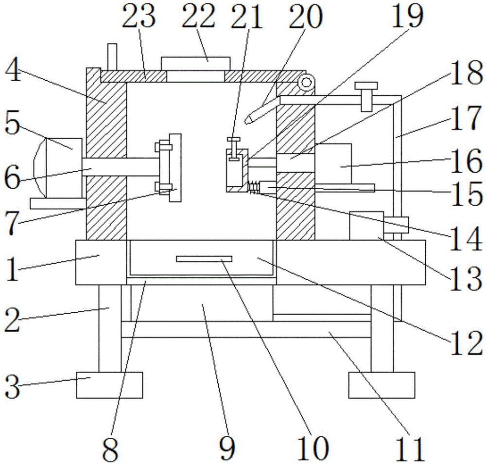
1. a processing table; 2. supporting legs; 3. a gasket; 4. processing a tank; 5. a stepping motor; 6. a rotating shaft; 7. grinding disc; 8. a support plate; 9. a waste liquid collection box; 10. a handle; 11. a support bar; 12. a waste collection tank; 13. a water pump; 14. a buffer spring; 15. a spring support frame; 16. a hydraulic cylinder; 17. a circulating water pipe; 18. a hydraulic lever; 19. a bearing groove; 20. a spray head; 21. a fastener; 22. a circulating fan; 23. a box cover; 24. a water filtering net.
Detailed Description
The technical solutions in the embodiments of the present invention will be described clearly and completely with reference to the accompanying drawings in the embodiments of the present invention, and it is obvious that the described embodiments are only some embodiments of the present invention, not all embodiments. Based on the embodiments in the present invention, all other embodiments obtained by a person skilled in the art without creative work belong to the protection scope of the present invention.
In the description of the present invention, it should be noted that the terms "center", "upper", "lower", "left", "right", "vertical", "horizontal", "inner", "outer", and the like indicate orientations or positional relationships based on the orientations or positional relationships shown in the drawings, and are only for convenience of description and simplification of description, but do not indicate or imply that the device or element referred to must have a specific orientation, be constructed and operated in a specific orientation, and thus, should not be construed as limiting the present invention; the terms "first," "second," and "third" are used for descriptive purposes only and are not to be construed as indicating or implying relative importance, and furthermore, unless otherwise explicitly stated or limited, the terms "mounted," "connected," and "connected" are to be construed broadly and may be, for example, fixedly connected, detachably connected, or integrally connected; can be mechanically or electrically connected; they may be connected directly or indirectly through intervening media, or they may be interconnected between two elements. The specific meaning of the above terms in the present invention can be understood in specific cases to those skilled in the art.
Referring to fig. 1-3, the utility model provides a pair of a grinding device for metal parts production: comprises a processing table 1, a processing tank 4 is fixedly connected above the processing table 1, a tank cover 23 is movably connected above the processing tank 4, processing scraps are prevented from splashing, cleaning and washing of the device are facilitated, manpower and material resources are saved, a circulating fan 22 is fixedly connected in the middle of the tank cover 23, a stepping motor 5 is fixedly connected to the outer wall of the left side of the processing tank 4, a rotating shaft 6 is fixedly connected to the output end of the stepping motor 5, a polishing disc 7 is movably connected to one end, away from the stepping motor 5, of the rotating shaft 6, a hydraulic cylinder 16 is fixedly connected to the outer wall of the right side of the processing tank 4, a hydraulic rod 18 is fixedly connected to the output end of the hydraulic cylinder 16, a bearing tank 19 is fixedly connected to one end, away from the hydraulic cylinder 16, a fastener 21 is movably connected to the inside of the top side of the bearing tank 19, and a spring support frame 15 fixedly connected to the inner wall of the right side of the processing tank 4 is arranged below the hydraulic rod 18, processing platform 1's the inside fixedly connected with backup pad 8 of centre department, the top swing joint of backup pad 8 has the garbage collection groove 12 that is located processing platform 1 inside, processing platform 1's below fixedly connected with waste liquid collection box 9, be favorable to the recycling of water resource, be favorable to preventing the waste of water resource, be favorable to the environmental protection, waste liquid collection box 9's right side outer wall fixedly connected with circulating pipe 17, circulating pipe 17 keeps away from waste liquid collection box 9's one end fixedly connected with shower nozzle 20, can effectively cool down polishing dish 7 when polishing the metal part, can effectively avoid the use of the too high temperature influence metal part, there is the water pump 13 of fixed connection in processing platform 1 top on the right side of processing groove 4.
Processing platform 1's below fixedly connected with supporting leg 2, supporting leg 2's below fixedly connected with gasket 3, circulating pipe 17's centre department and water pump 13 fixed connection, the inside of garbage collection groove 12 is equipped with water strainer 24, pass through hinge swing joint between case lid 23 and the processing groove 4, the top fixedly connected with handle of case lid 23, there is the bracing piece 11 of fixed connection in supporting leg 2 inboard below of waste liquid collecting box 9, the front side fixedly connected with handle 10 of garbage collection groove 12, the centre department outside of spring support frame 15 is equipped with buffer spring 14, can dismantle through the bolt and be connected between polishing dish 7 and the axis of rotation 6.
The working principle is as follows: the metal part to be processed is placed in the bearing groove 19, the rotating fastener 21 fixedly clamps the metal part to prevent the metal part from loosening and affecting the polishing quality, the box cover 23 is closed to prevent processing scraps from splashing, the cleaning and the cleaning of the device are facilitated, manpower and material resources are saved, the switch of the hydraulic cylinder 16 is turned on, the hydraulic rod 18 is made to move to drive the bearing groove 19 to move to a proper position, the switch of the stepping motor 5 is turned on, the rotating shaft 6 is made to rotate while the polishing disc 7 is made to move, the water pump 13 is turned on to make the spray nozzle 20 spray water, the temperature of the polishing disc 7 can be effectively reduced when the metal part is polished, the use of the metal part due to overhigh temperature can be effectively avoided, the switch of the circulating fan 22 is turned on, the gas in the processing groove 4 is made to circulate, the temperature of the gas in the processing groove 4 is lowered, the temperature reduction treatment is facilitated, the waste, the waste liquid gets into waste liquid collecting box 9, is favorable to the recycling of water resource, is favorable to preventing the waste of water resource, is favorable to the environmental protection.
Finally, it should be noted that: although the present invention has been described in detail with reference to the foregoing embodiments, it will be apparent to those skilled in the art that modifications and variations can be made in the embodiments or in part of the technical features of the embodiments without departing from the spirit and the scope of the invention.