CN213917127U - Vertical machining tool for sorting robot chassis - Google Patents
Vertical machining tool for sorting robot chassis Download PDFInfo
- Publication number
- CN213917127U CN213917127U CN202022114191.8U CN202022114191U CN213917127U CN 213917127 U CN213917127 U CN 213917127U CN 202022114191 U CN202022114191 U CN 202022114191U CN 213917127 U CN213917127 U CN 213917127U
- Authority
- CN
- China
- Prior art keywords
- bottom plate
- chassis
- sorting robot
- pressing
- machining tool
- Prior art date
- Legal status (The legal status is an assumption and is not a legal conclusion. Google has not performed a legal analysis and makes no representation as to the accuracy of the status listed.)
- Active
Links
Images

Abstract
The utility model relates to a vertical processing frock on sorting robot chassis, including a base, an adjustable support frame, a triangle bottom plate, two main reference columns, a compression leg, two clamp plate assemblies compress tightly the subassembly with a plurality of assistance, the base passes through the support frame with the triangle bottom plate and is connected, the length direction's of support frame top department is equipped with a plurality of T-shaped grooves, the central point of triangle bottom plate puts the department and is equipped with a circular shape boss, the top department of boss is equipped with compression leg and clamp plate assembly, the assistance compresses tightly the triangle department that the subassembly set up at the triangle bottom plate, main reference column sets up the both sides at the boss to peg graft with the top of triangle bottom plate. This vertical processing frock of letter sorting robot chassis has the position control and the processing of being convenient for, prevents to shake sword and product deformation, improves large tracts of land machining precision.
Description
Technical Field
The utility model relates to a letter sorting robot chassis processing technology field, especially a vertical processing frock on letter sorting robot chassis.
Background
At present, the letter sorting robot can carry out quick letter sorting to article, and the letter sorting robot needs use the chassis, and the arm rotates on the chassis, improves article letter sorting speed through the device of manipulator end.
The chassis of the robot needs to be processed before being installed, the chassis with a large area of conical surfaces cannot be processed by conventional machining, a cutter is easy to vibrate in the machining process, the machining precision is influenced, the installation and the use are influenced, and the product yield is reduced.
Therefore, a vertical machining tool for a sorting robot chassis is developed and used for solving the problems.
SUMMERY OF THE UTILITY MODEL
The utility model discloses the purpose is in order to overcome prior art not enough and provide a vertical processing frock on sorting robot chassis, has the position control and the processing of being convenient for, prevents to shake sword and product deformation, improves large tracts of land machining precision.
In order to achieve the above purpose, the utility model adopts the technical scheme that: a vertical processing tool for a sorting robot chassis comprises a base, an adjustable supporting frame, a triangular bottom plate, two main positioning columns, a pressing column, two pressing plate assemblies and a plurality of auxiliary pressing assemblies, the base is connected with the triangular bottom plate through a support frame, a plurality of T-shaped grooves are arranged at the top end of the support frame in the length direction, a circular boss is arranged at the center of the triangular bottom plate, the top end of the boss is provided with the pressing column and the pressing plate component, the auxiliary pressing components are arranged at the triangle of the triangle bottom plate, the main positioning columns are arranged at the two sides of the lug boss, and is inserted with the top end of the triangular bottom plate to adjust the T-shaped groove to a processing position, the main positioning column is inserted at the bottom of the chassis, the pressing column and the pressing plate assembly press the top of the chassis in a pressing mode, and the auxiliary pressing assembly presses the radial position of the chassis in an auxiliary mode.
Preferably, the pressing plate assembly comprises a main pressing plate and a supporting rod, the main pressing plate penetrates through the supporting rod, and the top end of the supporting rod is screwed with a locknut.
Preferably, the main pressure plate is provided with a U-shaped groove, and the support rod is arranged in the U-shaped groove in a penetrating mode.
Preferably, a square groove is arranged at the top end of the supporting frame in the width direction.
Preferably, the auxiliary pressing assembly comprises a square column and a cross rod, a square hole and a plurality of strip-shaped holes are formed in the square column, the square hole is perpendicular to the strip-shaped holes, and the cross rod penetrates through the square hole.
Preferably, one end of the cross rod is provided with a knob, the other end of the cross rod is provided with an arc opening, and the knob is far away from the center of the triangular bottom plate.
Preferably, through holes are formed in the periphery of the boss, and the through holes are arranged at the top end of the triangular base plate in a square shape.
Preferably, four corners of the base are respectively provided with a connecting hole.
Because of above-mentioned technical scheme's application, compared with the prior art, the utility model have the following advantage:
1. in the vertical processing tool for the sorting robot chassis, the support frame is convenient for processing articles with the length exceeding that of the main shaft, and the T-shaped groove and the square groove are arranged on the support frame, so that the chassis can be adjusted left and right;
2. the main positioning column and the main pressing plate limit six degrees of freedom of the chassis;
3. the auxiliary pressing assembly prevents the vibration cutter and the workpiece surface from deforming during processing, and the processing precision of a large-area conical surface is improved.
Drawings
Fig. 1 is a schematic structural view of a vertical machining tool of a sorting robot chassis of the present invention;
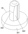
fig. 2 is a schematic structural view of the main positioning column of the present invention.
Detailed Description
The present invention will be described in further detail with reference to the accompanying drawings and specific embodiments.
In fig. 1 to 2, a vertical machining tool for a chassis of a sorting robot includes a base 10, an adjustable support frame 20, a triangular bottom plate 30, two main positioning columns 36, a pressing column 40, two pressing plate assemblies, and a plurality of auxiliary pressing assemblies. The main positioning column 36 is of a boss structure, the main positioning column 36 includes a bottom disk 361 and a cylinder 362 arranged at the center of the bottom disk 361, the top end of the cylinder 362 is of a conical structure, and a corrugated groove 363 is arranged at one side of the cylinder 362.
The base 10 is connected with the triangular bottom plate 30 through a support frame 20. The support frame 20 has a plurality of T-shaped grooves 22 at the top end in the longitudinal direction, and a square groove 21 at the top end in the width direction of the support frame 20. The center position department of triangle bottom plate 30 is equipped with a circular shape boss 35, the top department of boss 35 is equipped with compression leg 40 and pressure plate assembly, supplementary compress tightly the subassembly and set up in the triangle department of triangle bottom plate 30, main reference column 36 sets up the both sides at boss 35 to peg graft with the top of triangle bottom plate 30, adjust T-slot 22 to the processing position, main reference column 36 pegs graft in the bottom on chassis, compression leg 40 and pressure plate assembly are with the top crimping on chassis, supplementary compress tightly the subassembly and compress tightly the radial position of chassis is supplementary. A connection hole 101 is formed at each of four corners of the base 10. Through holes 31 are formed around the boss 35, and the through holes 31 are arranged at the top end of the triangular base plate 30 in a square shape.
The platen assembly includes a main platen 42 and a support rod 41. The main pressing plate 42 is inserted into the supporting rod 41, and a locknut is screwed on the top end of the supporting rod 41. The main pressing plate 42 is provided with a U-shaped groove 421. The support rod 41 is inserted into the U-shaped groove 421.
The auxiliary pressing assembly comprises a square column 50 and a cross rod 51, a square hole 502 and a plurality of strip-shaped holes 501 are formed in the square column 50, the square hole 502 and the strip-shaped holes 501 are perpendicular to each other, and the cross rod 51 penetrates through the square hole 502. One end of the cross bar 51 is provided with a knob 52, the other end of the cross bar 51 is provided with an arc opening 53, and the knob 52 is arranged away from the center of the triangular bottom plate 30.
The connecting hole 101 is fixed on a processing machine table, the position of the triangular bottom plate 30 is adjusted through the T-shaped groove 22 and the square groove 21, the bottom of a semi-finished chassis to be processed is inserted into the main positioning column 36, the top of the chassis is tightly pressed with the pressing column 40 through the main pressing plate 42, the periphery of the chassis is tightly pressed through the arc opening 53, and the surface of the chassis is processed through the processing center.
The utility model has the advantages of that:
1. the utility model relates to a vertical processing frock on letter sorting robot chassis, the use of support frame is convenient for exceed the processing of the article of main shaft length to be equipped with the left and right sides regulation on the chassis of being convenient for in T-slot and square groove on the support frame.
2. The main positioning column and the main pressing plate limit six degrees of freedom of the chassis.
3. The auxiliary pressing assembly prevents the vibration cutter and the workpiece surface from deforming during processing, and the processing precision of a large-area conical surface is improved.
The above is only a specific application example of the present invention, and does not constitute any limitation to the protection scope of the present invention. All the technical solutions formed by equivalent transformation or equivalent replacement fall within the protection scope of the present invention.
Claims (8)
1. The utility model provides a vertical processing frock of sorting robot chassis which characterized in that: the base is connected with the triangular bottom plate through the supporting frame, a plurality of T-shaped grooves are formed in the top end of the supporting frame in the length direction, a circular boss is arranged at the center of the triangular bottom plate, the pressing column is arranged at the top end of the boss, the pressing column is connected with the pressing plate assembly, the auxiliary pressing assembly is arranged at the triangular position of the triangular bottom plate, the main positioning columns are arranged on two sides of the boss and connected with the top end of the triangular bottom plate in an inserting mode, the T-shaped grooves are adjusted to the machining position, the main positioning columns are connected with the bottom of the base in an inserting mode, the pressing column is connected with the top of the base in a pressing mode through the pressing plate assembly, and the auxiliary pressing assembly presses the radial position of the base in an auxiliary mode.
2. The vertical machining tool for the chassis of the sorting robot according to claim 1, wherein the pressing plate assembly comprises a main pressing plate and a supporting rod, the main pressing plate is arranged on the supporting rod in a penetrating mode, and a check nut is screwed on the top end of the supporting rod.
3. The vertical machining tool for the chassis of the sorting robot according to claim 2, wherein a U-shaped groove is formed in the main pressing plate, and the support rod is arranged in the U-shaped groove in a penetrating manner.
4. The vertical machining tool for the sorting robot chassis according to claim 1, wherein a square groove is formed at the top end of the supporting frame in the width direction.
5. The vertical machining tool for the chassis of the sorting robot according to claim 1, wherein the auxiliary pressing assembly comprises a square column and a cross rod, a square hole and a plurality of strip-shaped holes are formed in the square column, the square hole and the strip-shaped holes are perpendicular to each other, and the cross rod is arranged in the square hole in a penetrating mode.
6. The vertical machining tool for the chassis of the sorting robot according to claim 5, wherein a knob is arranged at one end of the cross rod, an arc port is arranged at the other end of the cross rod, and the knob is arranged away from the center of the triangular bottom plate.
7. The vertical machining tool for the chassis of the sorting robot according to claim 1, wherein through holes are formed in the periphery of the boss, and the through holes are arranged at the top end of the triangular bottom plate in a square shape.
8. The vertical machining tool for the sorting robot chassis according to claim 1, wherein a connecting hole is formed at each of four corners of the base.
Priority Applications (1)
| Application Number | Priority Date | Filing Date | Title |
|---|---|---|---|
| CN202022114191.8U CN213917127U (en) | 2020-09-24 | 2020-09-24 | Vertical machining tool for sorting robot chassis |
Applications Claiming Priority (1)
| Application Number | Priority Date | Filing Date | Title |
|---|---|---|---|
| CN202022114191.8U CN213917127U (en) | 2020-09-24 | 2020-09-24 | Vertical machining tool for sorting robot chassis |
Publications (1)
| Publication Number | Publication Date |
|---|---|
| CN213917127U true CN213917127U (en) | 2021-08-10 |
Family
ID=77217834
Family Applications (1)
| Application Number | Title | Priority Date | Filing Date |
|---|---|---|---|
| CN202022114191.8U Active CN213917127U (en) | 2020-09-24 | 2020-09-24 | Vertical machining tool for sorting robot chassis |
Country Status (1)
| Country | Link |
|---|---|
| CN (1) | CN213917127U (en) |
-
2020
- 2020-09-24 CN CN202022114191.8U patent/CN213917127U/en active Active
Similar Documents
| Publication | Publication Date | Title |
|---|---|---|
| CN201016896Y (en) | Clamping device for milling sample piece | |
| CN213917127U (en) | Vertical machining tool for sorting robot chassis | |
| CN213917175U (en) | Large-sized flat plate part machining tool | |
| CN210938254U (en) | Electric tool accessory processing frock | |
| CN214321427U (en) | Non-motor vehicle license plate stamping forming machine | |
| CN211439112U (en) | Formula contour machining tool is inhaled to notebook keyboard preprocessing casing gas | |
| CN112775286A (en) | Precision stamping die capable of being positioned and adjusted | |
| CN2841269Y (en) | Spanner operation table | |
| CN216067092U (en) | Jig for baffle processing | |
| CN210938181U (en) | Machining jig for front arm of manipulator | |
| CN206084514U (en) | Pneumatic clamp | |
| CN219234650U (en) | Double-station clamping device | |
| CN219465475U (en) | Combined machining center clamp | |
| CN218857127U (en) | Blanket punching tool | |
| CN211760015U (en) | Multi-purpose dull and stereotyped frock clamp of machine tooling | |
| CN212919027U (en) | Processing tool | |
| CN216757776U (en) | Sheet metal part composite stamping device for printer | |
| CN204353812U (en) | A kind of movable fast-holding head | |
| CN210255849U (en) | Device for quickly clamping jig | |
| CN211660839U (en) | Numerical control precision punching machine for metal product production | |
| CN108406265A (en) | Workpiece fastens clamp system | |
| CN212824131U (en) | Thin wall part high accuracy shape frock of preapring for an unfavorable turn of events | |
| CN220217525U (en) | Tool clamp for hollow thin-wall product | |
| CN213470372U (en) | Fixing device for machining multiple holes in fixing base | |
| CN206393296U (en) | A kind of five-axis robot fixture |
Legal Events
| Date | Code | Title | Description |
|---|---|---|---|
| GR01 | Patent grant | ||
| GR01 | Patent grant |