CN213917042U - Double-head double-turret numerical control lathe - Google Patents
Double-head double-turret numerical control lathe Download PDFInfo
- Publication number
- CN213917042U CN213917042U CN202023213521.5U CN202023213521U CN213917042U CN 213917042 U CN213917042 U CN 213917042U CN 202023213521 U CN202023213521 U CN 202023213521U CN 213917042 U CN213917042 U CN 213917042U
- Authority
- CN
- China
- Prior art keywords
- numerical control
- power tool
- turret
- sliding table
- double
- Prior art date
- Legal status (The legal status is an assumption and is not a legal conclusion. Google has not performed a legal analysis and makes no representation as to the accuracy of the status listed.)
- Active
Links
Images


Abstract
A double-head double-turret numerically controlled lathe is mainly used for milling the outer circles and end faces of two ends of a slender shaft and various holes in the slender shaft. The left and right spindle clamp holder numerical control sliding tables are connected with the lathe bed in a sliding manner, and the left and right spindle clamp holders are respectively fixed on the left and right spindle clamp holder numerical control sliding tables; the left and right power tool turret cross numerical control sliding tables are in sliding connection with the lathe bed, and the left and right power tool turrets are in sliding connection with the left and right power tool turret cross numerical control sliding tables respectively; the left and right turn-milling composite power heads are respectively connected with a main shaft of the numerical control lathe; the hydraulic tailstock is connected with one end of the lathe body, and the cooling chip removal device is arranged at the other end of the lathe body. The utility model discloses product quality is reliable and stable, and is efficient, has filled internal blank to machine tool simultaneously at slender axles both ends.
Description
Technical Field
The utility model relates to the technical field of machine tools, specifically a double-end double-turret numerical control lathe.
Background
In the field of mechanical equipment, a slender shaft workpiece has large processing difficulty and difficult precision guarantee because of the sagging winding caused by dead weight in the processing process, and the existing machine tool can only process the shaft workpiece with smaller length and cannot meet the requirement that two ends of the shaft workpiece with the length-diameter ratio larger than 40 are processed simultaneously.
Disclosure of Invention
In order to overcome the defects of the prior art, the invention aims to provide the double-head double-turret numerical control lathe which aims to improve the processing quality of slender shaft workpieces and meet the requirement for simultaneously processing the two ends of the slender shaft workpieces.
In order to realize the aim, the utility model discloses numerical control lathe includes numerical control system, hydraulic system and centralized lubrication installation; the left and right spindle clamp holder numerical control sliding tables are connected with the lathe bed in a sliding mode along the transverse direction, and the left and right spindle clamp holders are fixed on the left and right spindle clamp holder numerical control sliding tables respectively; the left and right power tool turret cross numerical control sliding tables are connected with the lathe bed in a sliding mode along the transverse direction, and the left and right power tool turrets are respectively connected with the left and right power tool turret cross numerical control sliding tables in a sliding mode along the vertical direction; the left and right turn-milling composite power heads are respectively connected with a main shaft of the numerical control lathe; the hydraulic tailstock is connected with one end of the lathe body, and the cooling chip removal device is arranged at the other end of the lathe body.
The front surface of the lathe bed is of an inclined surface structure.
The numerical control sliding table body of the left and right main shaft holder numerical control sliding tables is fixed on the bottom surfaces of the left and right main shaft holder numerical control sliding tables, the sliding table body is in threaded connection with a main shaft holder numerical control sliding table ball screw arranged on a lathe bed, the sliding table body is in sliding connection with a transverse ball linear guide rail on the inclined surface of the lathe bed, and a main shaft holder numerical control sliding table servo motor drives the main shaft holder numerical control sliding table ball screw to drive the left and right main shaft holder numerical control sliding tables to transversely move along the transverse ball linear guide rail; the hydraulic brake disc fixed on the clamping seat body brakes the belt pulley through a brake pad, a front waterproof cover and a belt cover are arranged on the belt pulley, an encoder is arranged at the other end of the sleeve and on the clamping seat body, the encoder is connected with a main shaft clamping seat driving motor fixed on a left main shaft clamping seat numerical control sliding table and a right main shaft clamping seat numerical control sliding table, a rear waterproof cover is arranged outside the encoder, and a hydraulic piston of a hydraulic cylinder arranged in the clamping seat body moves to enable the collet to deform to clamp a workpiece.
The cross sliding table bodies of the left and right power tool turret cross numerical control sliding tables are arranged on the bottom surfaces of the left and right power tool turret cross numerical control sliding tables, the cross sliding table bodies are in threaded connection with power tool turret cross numerical control sliding table ball screws arranged on a machine body, the cross sliding table bodies are in sliding connection with transverse ball linear guide rails on the inclined surface of the machine body, and a power tool turret cross numerical control sliding table servo motor drives the power tool turret cross numerical control sliding table ball screws to drive the left and right power tool turret cross numerical control sliding tables to transversely move along the transverse ball linear guide rails; the power tool turret sliding table body is arranged on the bottom surfaces of the left and right power tool turrets, a power tool turret vertical ball screw is fixed on the cross sliding table body, the power tool turret sliding table body is in threaded connection with the power tool turret vertical ball screw, the power tool turret sliding table body is in sliding connection with a power tool turret vertical ball linear guide rail arranged on the cross sliding table body, and a power tool turret servo motor drives the power tool turret vertical ball screw to drive the left and right power tool turrets to vertically move along the power tool turret vertical ball linear guide rail; the cutter head bodies of the left and right power turrets are arranged on one side of the turret body, the transposition motor and the power cutter motor are fixed on the other side of the turret body, and the cutter seats are arranged on the cutter head bodies.
And a milling cutter disc and a stepping motor of the left and right turn-milling composite power heads are respectively arranged at two ends of the power head.
A tailstock support of the hydraulic tailstock is connected with a transverse ball linear guide rail through a guide rail clamp, an oil cylinder is fixed on the tailstock support, a sliding sleeve is installed together with a piston rod of the oil cylinder, and a tip is in rolling connection with the sliding sleeve.
The scraper type chip removal machine of the cooling chip removal device is connected with the chip removal machine motor, a cooling water tank is arranged on the side of the scraper type chip removal machine, and a water pump controls the cooling water tank to run.
The protective cover is arranged on the lathe bed.
Compared with the prior art, the utility model, have following advantage:
1. the utility model discloses mainly used is to milling process of slender axles class both ends excircle, terminal surface and all kinds of holes on it, and product quality is reliable and stable, and is efficient, has filled internal blank to the machine tool simultaneously at slender axles both ends.
2. The inclined lathe bed is adopted to cast the whole structure, so that the inclined lathe bed has enough strength and rigidity, and is compact in structure and not easy to deform.
3. The left and right main shaft clamping seats are adopted to clamp the workpiece, the rotation precision is high, the service life is long, and the workpiece is hydraulically and automatically centered and clamped, so that the clamping device is quick, convenient and labor-saving; the production requirements of various varieties can be met by replacing the collet; the left and right numerical control sliding tables of the main shaft clamping seat are arranged below the main shaft clamping seat, so that the workpiece can be quickly aligned when being replaced.
4. The configuration of the high-power left and right power tool turrets can facilitate centralized processing of multiple processes, and is particularly suitable for simultaneously processing two ends of a slender shaft workpiece; the power tool turret is provided with a numerical control cross sliding table, and various processing technological requirements such as turning, milling, drilling, boring, tapping and the like can be met by clamping once.
5. The numerical control sliding table matched with the main shaft clamping seat and the power tool turret adopts a high-speed ball linear guide rail, so that high-speed feeding can be realized, and the precision of a machine tool is ensured; the ball screw adopts a locking and pulling design of supporting seats at two ends, and the ball screw can eliminate transmission backlash and compensate errors caused by temperature rise in advance through prepressing treatment, so that the positioning precision is ensured; the servo motor and the ball screw are directly driven, so that the accumulated error of belt drive is avoided, and the repetition and positioning accuracy is high; the ball screw is supported by the high-precision angular contact ball bearing, so that the ball screw has the advantages of high positioning precision, high speed, flexible and changeable processing and the like, and the processing position can be quickly and accurately adjusted after a product is replaced.
6. The left and right turning and milling composite power heads are arranged and can be linked with a main shaft of a numerical control lathe to quickly finish the turning and milling operation of two ends of a slender shaft workpiece.
7. The numerical control system adopts a Sena double-channel numerical control system for control, and is suitable for the needs of multi-variety and multi-procedure centralized processing.
Drawings
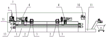
Fig. 1 is a schematic structural diagram of the present invention.
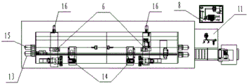
Fig. 2 is a top view of fig. 1.
Fig. 3 is a side view of fig. 1.
Fig. 4 is a schematic structural view of the spindle holder of fig. 1.
Fig. 5 is a side view of fig. 4.
Fig. 6 is a schematic structural view of the connection between the numerical control sliding table of the spindle holder and the machine tool shown in fig. 1.
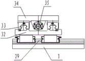
Fig. 7 is a schematic structural diagram of the connection of the power turret cross numerical control sliding table and the bed body and the connection of the power turret and the power turret cross numerical control sliding table in fig. 1.
Fig. 8 is a side view of fig. 7.
Fig. 9 is a schematic view of the power turret of fig. 1.
Fig. 10 is a schematic structural diagram of the turning and milling composite power head of fig. 1.
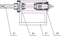
Fig. 11 is a schematic structural view of the hydraulic tailstock of fig. 1.
Fig. 12 is a schematic structural view of the cooling chip removal device of fig. 1.
Detailed Description
As shown in fig. 1, fig. 2, fig. 3, fig. 4, fig. 5, fig. 6, fig. 7, fig. 8, fig. 9, fig. 10, fig. 11, and fig. 12, the present invention includes a numerical control system 8 and a hydraulic system 9, wherein the left and right spindle clamp numerical control sliding tables 3 are slidably connected with the bed 1 along the transverse direction, and the left and right spindle clamps 2 are respectively fixed on the left and right spindle clamp numerical control sliding tables 3; the left and right power tool turret cross numerical control sliding tables 5 are connected with the lathe bed 1 in a sliding mode along the transverse direction, and the left and right power tool turrets 4 are respectively connected with the left and right power tool turret cross numerical control sliding tables 5 in a sliding mode along the vertical direction; the left and right turning and milling composite power heads 6 are respectively connected with a main shaft of the numerical control lathe; the hydraulic tailstock 7 is connected with one end of the lathe body 1, the cooling chip removal device 11 is installed at the other end of the lathe body 1, and the lathe body 1 is provided with the protective cover 12.
The front surface of the lathe bed 1 is of an inclined surface structure, has enough strength and rigidity, and is compact in structure and not easy to deform.
The left and right main shaft holder numerical control sliding tables 3 are fixed on the bottom surfaces of the left and right main shaft holder numerical control sliding tables 3, the sliding table body 31 is in threaded connection with a main shaft holder numerical control sliding table ball screw 30 arranged on the lathe bed 1, the sliding table body 31 is in sliding connection with a transverse ball linear guide 29 on the inclined surface of the lathe bed 1, the numerical control system 8 controls a main shaft holder numerical control sliding table servo motor 13 to drive the main shaft holder numerical control sliding table ball screw 30 to drive the left and right main shaft holder numerical control sliding tables 3 to transversely move along the transverse ball linear guide 29, and the left and right main shaft holder numerical control sliding tables 3 are arranged below the main shaft holder 2 and can be quickly aligned when a workpiece is replaced; a bearing 28 is arranged between a sleeve 27 and a clamp seat body 26 of the left and right main shaft clamp seats 2, the belt pulley 18 is connected with one end of the sleeve 27, the collet 19 is in wedge fit with an inner hole of the sleeve 27, a spline at one end of the sleeve 27 is used for transmitting torque for the collet 19, a hydraulic brake disc 23 fixed on the clamp seat body 26 brakes the belt pulley 18 through a brake pad 17, a front waterproof cover 21 and a belt cover 22 are arranged on the belt pulley 18, an encoder 25 is arranged on the other end of the sleeve 27 and the clamp seat body 26, the encoder 25 is connected with a main shaft clamp seat driving motor 14 fixed on the left and right main shaft clamp seat numerical control sliding tables 3, a hydraulic piston 20 of a hydraulic cylinder arranged in the clamp seat body 26 moves to enable the collet 19 to deform and clamp a workpiece, the numerical control system 8 controls the main shaft clamp seat driving motor 14 to drive the belt pulley 18 to operate, so as to drive the workpiece to rotate, and a rear waterproof cover 24 is arranged outside the encoder 25. The utility model discloses a 2 centre gripping work pieces of left and right main shaft holder, the gyration precision is high, long service life, through the main shaft holder numerical control slip table servo motor 13 drive main shaft holder numerical control slip table ball screw 30 drive the slip table body 31 and remove to adapt to different length work piece centre gripping needs, and 2 accessible hydraulic system 9 of main shaft holder carry out hydraulic pressure self-centering to the work piece and press from both sides tightly, quick, convenient, laborsaving, can satisfy many varieties production requirement through changing collet chuck 19.
The cross sliding table body 32 of the left and right power tool turret cross numerical control sliding tables 5 is arranged on the bottom surfaces of the left and right power tool turret cross numerical control sliding tables 5, the cross sliding table body 32 is in threaded connection with a power tool turret cross numerical control sliding table ball screw 36 arranged on the machine body 1, the cross sliding table body 32 is in sliding connection with a transverse ball linear guide 29 on the inclined surface of the machine body 1, the numerical control system 8 controls the power tool turret cross numerical control sliding table servo motor 15 and drives the power tool turret cross numerical control sliding table ball screw 36 to drive the left and right power tool turret cross numerical control sliding tables 5 to transversely move along the transverse ball linear guide 29; the power tool turret slide body 34 is arranged on the bottom surfaces of the left and right power tool turrets 4, the power tool turret vertical ball screw 35 is fixed on the cross slide body 32, the power tool turret slide body 34 is in threaded connection with the power tool turret vertical ball screw 35, the power tool turret slide body 34 is in sliding connection with the power tool turret vertical ball linear guide rail 33 arranged on the cross slide body 32, the numerical control system 8 controls the power tool turret servo motor 16, and drives the power tool turret vertical ball screw 35 to drive the left and right power tool turrets 4 to vertically move along the power tool turret vertical ball linear guide rail 33; the cutter head body 38 of the left and right power cutter towers 4 is arranged on one side of the cutter head body 37, the indexing motor 40 and the power cutter motor 41 are fixed on the other side of the cutter head body 37, the cutter seat 39 is arranged on the cutter head body 38, the indexing motor 40 and the power cutter motor 41 of the left and right power cutter towers 4 are controlled by the numerical control system 8 to operate, and different cutters are arranged on the cutter seat 39 to finish different working procedures of workpieces.
The milling cutter disc 42 and the stepping motor 44 of the left and right turn-milling composite power heads 6 are respectively arranged at two ends of the power head 43. The turning and milling composite power head 6 controls a stepping motor 44 through a numerical control system 8, and is linked with the main shaft to complete milling and flattening processing of two ends of a workpiece.
A tailstock support 47 of the hydraulic tailstock 7 is connected with the transverse ball linear guide rail 29 through a guide rail clamp, the oil cylinder 45 is fixed on the tailstock support 47, the sliding sleeve 46 and a piston rod of the oil cylinder 45 are installed together, and a tip 48 is in rolling connection with the sliding sleeve 2.
The scraper type chip removal machine 49 of the cooling chip removal device 11 is connected with a chip removal machine motor 52, a cooling water tank 50 is arranged on the side of the scraper type chip removal machine 49, and a water pump 51 controls the cooling water tank 50 to operate. The cooling liquid is pressurized and sent to a machining area for cooling and chip flushing, and the generated chips are collected by a chip removal machine 49 and are conveyed into a chip accumulation trolley 53.
The centralized lubricating device 10 is a purchased part, consists of an aluminum alloy oil tank, an intermittent oiling machine, a filter, an oil distributor, a sensor and the like, has three starting modes of lubrication, intermittence and memory, and can adjust the lubrication and intermittence time; a liquid level switch is arranged, and the buzzer can give out an alarm when the oil quantity is insufficient; the system is provided with a pressure relief device, and the constant pressure function of a pressure relief valve can protect the pump and the pipeline from damage; the panel indicator light can display the action and state of the oiling machine, and the motor can continuously run for a long time.
Claims (8)
1. The utility model provides a two sword tower numerical control lathes of double-end which characterized in that: the numerically controlled lathe comprises a numerically controlled system (8), a hydraulic system (9) and a centralized lubricating device (10); the left and right spindle clamp numerical control sliding tables (3) are connected with the lathe bed (1) in a sliding mode along the transverse direction, and the left and right spindle clamp seats (2) are fixed on the left and right spindle clamp numerical control sliding tables (3) respectively; the left and right power tool turret cross numerical control sliding tables (5) are connected with the lathe bed (1) in a sliding mode along the transverse direction, and the left and right power tool turrets (4) are respectively connected with the left and right power tool turret cross numerical control sliding tables (5) in a sliding mode along the vertical direction; the left and right turning and milling composite power heads (6) are respectively connected with a main shaft of the numerical control lathe; the hydraulic tailstock (7) is connected with one end of the lathe body (1), and the cooling chip removal device (11) is arranged at the other end of the lathe body (1).
2. The double-ended double-turret numerically controlled lathe according to claim 1, characterized in that: the front surface of the lathe bed (1) is of an inclined surface structure.
3. The double-ended double-turret numerically controlled lathe according to claim 1, characterized in that: the numerical control sliding table is characterized in that sliding table bodies (31) of the left and right main shaft clamping seat numerical control sliding tables (3) are fixed on the bottom surfaces of the left and right main shaft clamping seat numerical control sliding tables (3), the sliding table bodies (31) are in threaded connection with main shaft clamping seat numerical control sliding table ball screws (30) arranged on the machine body (1), the sliding table bodies (31) are in sliding connection with transverse ball linear guide rails (29) on the inclined surface of the machine body (1), and a main shaft clamping seat numerical control sliding table servo motor (13) drives the main shaft clamping seat numerical control sliding table ball screws (30) to drive the left and right main shaft clamping seat numerical control sliding tables (3) to transversely move along the transverse ball linear guide rails (29); a bearing (28) is arranged between a sleeve (27) and a clamping seat body (26) of the left and right main shaft clamping seats (2), a belt pulley (18) is connected at one end of the sleeve (27), a collet (19) is in wedge fit with an inner hole of the sleeve (27), a spline at one end of the sleeve (27) is used for transmitting torque for the collet (19), a hydraulic brake disc (23) fixed on the clamping seat body (26) brakes the belt pulley (18) through a brake pad (17), a front waterproof cover (21) and a belt cover (22) are arranged on the belt pulley (18), an encoder (25) is arranged at the other end of the sleeve (27) and on the clamp seat body (26), the encoder (25) is connected with a main shaft clamp seat driving motor (14) fixed on the left and right main shaft clamp seat numerical control sliding tables (3), a rear waterproof cover (24) is arranged outside the encoder (25), and a hydraulic piston (20) of a hydraulic cylinder arranged in the clamp seat body (26) moves to enable the collet chuck (19) to deform to clamp a workpiece.
4. The double-ended double-turret numerically controlled lathe according to claim 1, characterized in that: the cross sliding table bodies (32) of the left and right power tool turret cross numerical control sliding tables (5) are arranged on the bottom surfaces of the left and right power tool turret cross numerical control sliding tables (5), the cross sliding table bodies (32) are in threaded connection with power tool turret cross numerical control sliding table ball screws (36) arranged on the lathe body (1), the cross sliding table bodies (32) are in sliding connection with transverse ball linear guide rails (29) on the inclined surface of the lathe body (1), and a power tool turret cross numerical control sliding table servo motor (15) drives the power tool turret cross numerical control sliding table ball screws (36) to drive the left and right power tool turret cross numerical control sliding tables (5) to transversely move along the transverse ball linear guide rails (29); the power tool turret sliding table body (34) is arranged on the bottom surfaces of the left and right power tool turrets (4), a power tool turret vertical ball screw (35) is fixed on the cross sliding table body (32), the power tool turret sliding table body (34) is in threaded connection with the power tool turret vertical ball screw (35), the power tool turret sliding table body (34) is in sliding connection with a power tool turret vertical ball linear guide rail (33) arranged on the cross sliding table body (32), and a power tool turret servo motor (16) drives the power tool turret vertical ball screw (35) to drive the left and right power tool turrets (4) to vertically move along the power tool turret vertical ball linear guide rail (33); the cutter head body (38) of the left and right power turrets (4) is arranged on one side of the turret body (37), the indexing motor (40) and the power cutter motor (41) are fixed on the other side of the turret body (37), and the cutter seat (39) is arranged on the cutter head body (38).
5. The double-ended double-turret numerically controlled lathe according to claim 1, characterized in that: and a milling cutter disc (42) and a stepping motor (44) of the left and right turn-milling composite power heads (6) are respectively arranged at two ends of the power head (43).
6. The double-ended double-turret numerically controlled lathe according to claim 1, characterized in that: a tailstock support (47) of the hydraulic tailstock (7) is connected with a transverse ball linear guide rail (29) through a guide rail clamp, an oil cylinder (45) is fixed on the tailstock support (47), a sliding sleeve (46) is installed together with a piston rod of the oil cylinder (45), and a tip (48) is in rolling connection with the sliding sleeve (46).
7. The double-ended double-turret numerically controlled lathe according to claim 1, characterized in that: the scraper type chip removal machine (49) of the cooling chip removal device (11) is connected with a chip removal machine motor (52), a cooling water tank (50) is arranged on the side of the scraper type chip removal machine (49), and a water pump (51) controls the cooling water tank (50) to operate.
8. The double-ended double-turret numerically controlled lathe according to claim 1, characterized in that: the lathe bed (1) is provided with a protective cover (12).
Priority Applications (1)
| Application Number | Priority Date | Filing Date | Title |
|---|---|---|---|
| CN202023213521.5U CN213917042U (en) | 2020-12-28 | 2020-12-28 | Double-head double-turret numerical control lathe |
Applications Claiming Priority (1)
| Application Number | Priority Date | Filing Date | Title |
|---|---|---|---|
| CN202023213521.5U CN213917042U (en) | 2020-12-28 | 2020-12-28 | Double-head double-turret numerical control lathe |
Publications (1)
| Publication Number | Publication Date |
|---|---|
| CN213917042U true CN213917042U (en) | 2021-08-10 |
Family
ID=77156386
Family Applications (1)
| Application Number | Title | Priority Date | Filing Date |
|---|---|---|---|
| CN202023213521.5U Active CN213917042U (en) | 2020-12-28 | 2020-12-28 | Double-head double-turret numerical control lathe |
Country Status (1)
| Country | Link |
|---|---|
| CN (1) | CN213917042U (en) |
Cited By (1)
| Publication number | Priority date | Publication date | Assignee | Title |
|---|---|---|---|---|
| CN116748907A (en) * | 2023-08-17 | 2023-09-15 | 沈阳长隆精密机械科技有限公司 | Tool machine with structure suitable for processing middle-large thin-wall spinning pipe fitting |
-
2020
- 2020-12-28 CN CN202023213521.5U patent/CN213917042U/en active Active
Cited By (1)
| Publication number | Priority date | Publication date | Assignee | Title |
|---|---|---|---|---|
| CN116748907A (en) * | 2023-08-17 | 2023-09-15 | 沈阳长隆精密机械科技有限公司 | Tool machine with structure suitable for processing middle-large thin-wall spinning pipe fitting |
Similar Documents
| Publication | Publication Date | Title |
|---|---|---|
| CN106625030B (en) | composite flexible manufacturing unit | |
| CN211102672U (en) | Double-spindle double-channel turning and milling composite machine tool | |
| CN201304511Y (en) | Drill lathe for numerical control bearing retainer | |
| CN102229046A (en) | Machine tool | |
| CN110014300A (en) | A kind of complex machining device for monkey wrench | |
| CN203863344U (en) | Connecting rod bolt hole and step face finishing machine | |
| CN213917042U (en) | Double-head double-turret numerical control lathe | |
| CN109894631B (en) | Numerical control double-sided lathe of motor shell | |
| CN111037294A (en) | Full-automatic numerical control machine tool for machining crankshaft oil hole | |
| CN211564587U (en) | Wheel spoke multiaxis drilling equipment | |
| CN104816160B (en) | A kind of wagon drill combined machine | |
| CN111347065A (en) | Vertical numerical control boring machine | |
| CN211218800U (en) | Special equipment for drilling straight oil hole or oblique oil hole on crankshaft | |
| CN201217149Y (en) | Horizontal numerical control boring wheeling machine | |
| CN210817529U (en) | Automatic horizontal milling and boring machine | |
| CN207629244U (en) | A kind of thin wall and deep hole boring machine tool | |
| CN114192851A (en) | Milling machine tool for planet carrier planet wheel mounting surface and technological method thereof | |
| CN112974864A (en) | Numerical control full-automatic camshaft double-turret excircle lathe | |
| CN111054944A (en) | Special equipment for drilling straight oil hole or oblique oil hole on crankshaft | |
| CN2619745Y (en) | Machine tool for machining plane in ultra-length deep cavity | |
| CN101905335A (en) | Inner bore processing equipment of motor base | |
| CN101988873B (en) | Processing machine tool for low-power sulphur print sample | |
| CN214392463U (en) | Horizontal high-speed numerical control drilling machine for multi-spindle petroleum pipeline | |
| CN215279992U (en) | Horizontal deep hole drilling and boring machine for processing porous workpiece | |
| CN217570976U (en) | Heavy large-aperture deep hole drilling and boring machine tool |
Legal Events
| Date | Code | Title | Description |
|---|---|---|---|
| GR01 | Patent grant | ||
| GR01 | Patent grant |