CN213914015U - Powder raw material grinding device for refractory bricks - Google Patents
Powder raw material grinding device for refractory bricks Download PDFInfo
- Publication number
- CN213914015U CN213914015U CN202022712943.0U CN202022712943U CN213914015U CN 213914015 U CN213914015 U CN 213914015U CN 202022712943 U CN202022712943 U CN 202022712943U CN 213914015 U CN213914015 U CN 213914015U
- Authority
- CN
- China
- Prior art keywords
- fixedly connected
- pipe
- dust
- water tank
- intercommunication
- Prior art date
- Legal status (The legal status is an assumption and is not a legal conclusion. Google has not performed a legal analysis and makes no representation as to the accuracy of the status listed.)
- Active
Links
Images


Landscapes
- Furnace Housings, Linings, Walls, And Ceilings (AREA)
Abstract
The utility model discloses a resistant firebrick powder raw materials milling equipment, comprising a base plate, the left side fixedly connected with crocus case at bottom plate top, the bottom fixedly connected with sloping block of crocus incasement wall, the left bottom intercommunication of crocus case has row material pipe. The utility model discloses a set up the fixed plate, second servo motor, the flabellum, the water tank, the filler pipe, filter shell, the fiber filter layer, the drinking-water pipe, the suction pump, first installation mechanism, the outlet pipe, violently the pipe, first fixed establishment, the shower nozzle, go out the dirt pipe, the suction cleaner, second installation mechanism, the dust absorption pipe, second fixed establishment and suction hood mutually support, the advantage of automatic dust removal has been reached, make resistant firebrick powder raw materials when carrying out the crocus, can effectually absorb the dust that the crocus produced, then spray water dust fall, avoided the workman to inhale the problem that the dust caused harm to workman's healthy for a long time, guaranteed that workman's is healthy, can satisfy workman's user demand.
Description
Technical Field
The utility model relates to a resistant firebrick processing technology field specifically is resistant firebrick powder raw materials milling equipment.
Background
The refractory material is divided into two kinds, that is, an unshaped refractory material and a shaped refractory material, the unshaped refractory material is also called a castable and is a mixed powder particle consisting of a plurality of aggregates or aggregates and one or more adhesives, when in use, the unshaped refractory material must be matched with one or more liquids to be stirred uniformly, and has stronger fluidity, and the shaped refractory material is generally a refractory brick, has standard shape and can be cut and processed temporarily according to the needs.
Firebrick powder raw materials need use raw materials milling equipment when adding man-hour, and present raw materials milling equipment has following shortcoming: current raw materials milling equipment does not have the function of automatic dust removal, leads to resistant firebrick powder raw materials when carrying out the crocus, produces a large amount of dust easily, and the workman inhales the dust for a long time and causes harm to workman's healthy, can't satisfy workman's user demand.
SUMMERY OF THE UTILITY MODEL
An object of the utility model is to provide a resistant firebrick powder raw materials milling equipment possesses the advantage of automatic dust removal, has solved current raw materials milling equipment and has not had the function of automatic dust removal, leads to resistant firebrick powder raw materials when carrying out the crocus, produces a large amount of dusts easily, and the workman inhales the problem that the dust caused harm to workman's healthy for a long time.
In order to achieve the above object, the utility model provides a following technical scheme: refractory brick powder raw materials milling equipment, comprising a base plate, the left side fixedly connected with crocus case at bottom plate top, the bottom fixedly connected with sloping block of crocus incasement wall, the left bottom intercommunication of crocus case has row material pipe, the inner chamber intercommunication of arranging the material pipe has row material valve, the equal fixedly connected with first servo motor in both sides at the positive top of crocus case, the output of first servo motor runs through to the inner chamber of crocus case and fixedly connected with crushing roller, the surperficial fixedly connected with of crushing roller smashes the tooth, the back fixedly connected with pivot of crushing roller, the rear end cover of pivot has connect the bearing, the back of bearing and the inner wall fixed connection of crocus case, the top of crocus incasement wall both sides all fixedly connected with baffle, the left side fixedly connected with fixed plate at crocus roof, the left side fixedly connected with second servo motor of fixed plate, the output end of the second servo motor penetrates to the right side of the fixing plate, fan blades are fixedly connected to the surface of the fixing plate, a water tank is fixedly connected to the right side of the top of the bottom plate, a water feeding pipe is communicated with the top of the water tank, a filter shell is fixedly connected to the top of one side of the inner wall of the water tank, a fiber filter layer is fixedly connected to the inner wall of the filter shell, a water pumping pipe is communicated with the bottom of the right side of the water tank, one end, away from the water tank, of the water pumping pipe is communicated with a water pumping pump, a first mounting mechanism is arranged on the left side of the water pumping pump, the top of the water pumping pump is communicated with a water outlet pipe, one end, away from the water pumping pump, of the water outlet pipe penetrates to an inner cavity of the water tank and is communicated with a transverse pipe, first fixing mechanisms are arranged on two sides of the top of the transverse pipe, the bottom of the transverse pipe is communicated with a spray head, the left side of the water tank is communicated with a dust outlet pipe, and a dust suction machine is communicated with the dust outlet pipe, the right side of dust catcher is provided with second installation mechanism, the top intercommunication of dust catcher has the dust absorption pipe, the right side of dust absorption pipe is provided with second fixed establishment, the left side intercommunication of dust absorption pipe has the suction hood.
Preferably, first installation mechanism includes first mounting panel, the bottom fixed connection on bolt and water tank right side is passed through on the right side of first mounting panel, the first erection column of the equal fixedly connected with in top and the bottom on first mounting panel right side, the right side of first erection column and the left side fixed connection of suction pump.
Preferably, the first fixing mechanism comprises a first fixing block, the bottom of the first fixing block is fixedly connected with the bottom of the filter shell through a bolt, the bottom of the first fixing block is fixedly connected with a first fixing column, and the bottom of the first fixing column is fixedly connected with the top of the transverse pipe.
Preferably, second installation mechanism includes the second mounting panel, the left side fixed connection of bolt and water tank is passed through in the left side of second mounting panel, the left side fixedly connected with second erection column of second mounting panel, the left side of second erection column and the right side fixed connection of dust catcher.
Preferably, the second fixing mechanism comprises a second fixing block, the left side of the second fixing block is fixedly connected with the top of the left side of the water tank through a bolt, a second fixing column is fixedly connected to the left side of the second fixing block, and the left side of the second fixing column is fixedly connected with the right side of the dust collection pipe.
Compared with the prior art, the beneficial effects of the utility model are as follows:
1. the utility model discloses a set up the fixed plate, second servo motor, the flabellum, the water tank, the filler pipe, filter shell, the fiber filter layer, the drinking-water pipe, the suction pump, first installation mechanism, the outlet pipe, violently the pipe, first fixed establishment, the shower nozzle, go out the dirt pipe, the suction cleaner, second installation mechanism, the dust absorption pipe, second fixed establishment and suction hood mutually support, the advantage of automatic dust removal has been reached, make resistant firebrick powder raw materials when carrying out the crocus, can effectually absorb the dust that the crocus produced, then spray water dust fall, avoided the workman to inhale the problem that the dust caused harm to workman's healthy for a long time, guaranteed that workman's is healthy, can satisfy workman's user demand.
2. The utility model discloses a set up the fixed plate, second servo motor and flabellum mutually support, play the effect of blowing the dust, through setting up the filler pipe, play convenient watered effect to the inner chamber of water tank, through setting up the fiber filter layer, play filterable effect to the dust, through setting up first installation mechanism, play fixed mounting's effect to the suction pump, through setting up first fixed establishment, to violently playing fixed stay's effect with the shower nozzle, through setting up second installation mechanism, play fixed mounting's effect to the dust catcher, through setting up second fixed establishment, play fixed stay's effect to dust absorption pipe and suction hood.
Drawings
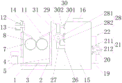
FIG. 1 is a schematic structural view of the present invention;
FIG. 2 is an enlarged view of the cross section of the internal structure of the water tank of the present invention;
fig. 3 is an enlarged view of the overlooking structure section of the milling box of the utility model.
In the figure: 1. a base plate; 2. a milling box; 3. a sloping block; 4. a discharge pipe; 5. a discharge valve; 6. a first servo motor; 7. a crushing roller; 8. crushing teeth; 9. a rotating shaft; 10. a bearing; 11. a baffle plate; 12. a fixing plate; 13. a second servo motor; 14. a fan blade; 15. a water tank; 16. a water feeding pipe; 17. a filter shell; 18. a fibrous filtration layer; 19. a water pumping pipe; 20. a water pump; 21. a first mounting mechanism; 211. a first mounting plate; 212. a first mounting post; 22. a water outlet pipe; 23. a transverse tube; 24. a first fixing mechanism; 241. a first fixed block; 242. a first fixed column; 25. a spray head; 26. a dust outlet pipe; 27. a dust collector; 28. a second mounting mechanism; 281. a second mounting plate; 282. a second mounting post; 29. a dust collection pipe; 30. a second fixing mechanism; 301. a second fixed block; 302. a second fixed column; 31. a dust hood.
Detailed Description
The technical solutions in the embodiments of the present invention will be described clearly and completely with reference to the accompanying drawings in the embodiments of the present invention, and it is obvious that the described embodiments are only some embodiments of the present invention, not all embodiments. Based on the embodiments in the present invention, all other embodiments obtained by a person skilled in the art without creative work belong to the protection scope of the present invention.
In the description herein, it is to be understood that the terms "center," "upper," "lower," "front," "rear," "left," "right," "vertical," "horizontal," "top," "bottom," "inner," "outer," and the like are used in the orientations and positional relationships indicated in the drawings to facilitate the description of the patent and to simplify the description, but do not indicate or imply that the referenced device or element must have a particular orientation, be constructed and operated in a particular orientation, and thus are not to be considered limiting of the patent. In the description of the present application, it should be noted that unless otherwise explicitly stated or limited, the terms "mounted," "connected," and "disposed" are to be construed broadly and can, for example, be fixedly connected, disposed, detachably connected, disposed, or integrally connected and disposed. The specific meaning of the above terms in this patent may be understood by those of ordinary skill in the art as appropriate.
Referring to fig. 1-3, a refractory brick powder raw material grinding device comprises a base plate 1, a grinding box 2 is fixedly connected to the left side of the top of the base plate 1, an inclined block 3 is fixedly connected to the bottom of the inner wall of the grinding box 2, a discharge pipe 4 is communicated with the bottom of the left side of the grinding box 2, a discharge valve 5 is communicated with the inner cavity of the discharge pipe 4, first servo motors 6 are fixedly connected to both sides of the front top of the grinding box 2, the output end of the first servo motor 6 penetrates through the inner cavity of the grinding box 2 and is fixedly connected with a grinding roller 7, a grinding tooth 8 is fixedly connected to the surface of the grinding roller 7, a rotating shaft 9 is fixedly connected to the back of the grinding roller 7, a bearing 10 is sleeved on the rear end of the rotating shaft 9, the back of the bearing 10 is fixedly connected to the inner wall of the grinding box 2, a baffle 11 is fixedly connected to the tops of both sides of the inner wall of the grinding box 2, and a fixing plate 12 is fixedly connected to the left side of the top of the grinding box 2, a second servo motor 13 is fixedly connected to the left side of the fixing plate 12, the output end of the second servo motor 13 penetrates through the right side of the fixing plate 12, fan blades 14 are fixedly connected to the surface of the fixing plate 12, a water tank 15 is fixedly connected to the right side of the top of the bottom plate 1, a water feeding pipe 16 is communicated with the top of the water tank 15, a filter shell 17 is fixedly connected to the top of one side of the inner wall of the water tank 15, a fiber filter layer 18 is fixedly connected to the inner wall of the filter shell 17, a water pumping pipe 19 is communicated with the bottom of the right side of the water tank 15, a water pumping pump 20 is communicated with one end of the water pumping pipe 19, which is far away from the water tank 15, a first mounting mechanism 21 is arranged on the left side of the water pumping pump 20, a water outlet pipe 22 is communicated with the top of the water outlet pipe 22, one end of the water outlet pipe 22, which is far away from the water pumping pump 20, penetrates through the inner cavity of the water tank 15 and is communicated with a transverse pipe 23, first fixing mechanisms 24 are arranged on both sides of the top of the transverse pipe 23, and a spray nozzle 25 is communicated with the bottom of the transverse pipe 23, a dust outlet pipe 26 is communicated with the left side of the water tank 15, a dust collector 27 is communicated with one end of the dust outlet pipe 26, which is far away from the water tank 15, a second mounting mechanism 28 is arranged on the right side of the dust collector 27, a dust suction pipe 29 is communicated with the top of the dust collector 27, a second fixing mechanism 30 is arranged on the right side of the dust suction pipe 29, a dust suction hood 31 is communicated with the left side of the dust suction pipe 29, the first mounting mechanism 21 comprises a first mounting plate 211, the right side of the first mounting plate 211 is fixedly connected with the bottom of the right side of the water tank 15 through bolts, the top and the bottom of the right side of the first mounting plate 211 are both fixedly connected with a first mounting column 212, the right side of the first mounting column 212 is fixedly connected with the left side of the water suction pump 20, the first fixing mechanism 24 comprises a first fixing block 241, the bottom of the first fixing block 241 is fixedly connected with the bottom of the filter shell 17 through bolts, the bottom of the first fixing block 241 is fixedly connected with a first fixing column 242, the bottom of the first fixing column 242 is fixedly connected with the top of the transverse pipe 23, the second mounting mechanism 28 comprises a second mounting plate 281, the left side of the second mounting plate 281 is fixedly connected with the left side of the water tank 15 through a bolt, the left side of the second mounting plate 281 is fixedly connected with a second mounting post 282, the left side of the second mounting post 282 is fixedly connected with the right side of the dust collector 27, the second fixing mechanism 30 comprises a second fixing block 301, the left side of the second fixing block 301 is fixedly connected with the top of the left side of the water tank 15 through a bolt, the left side of the second fixing block 301 is fixedly connected with a second fixing post 302, the left side of the second fixing post 302 is fixedly connected with the right side of the dust collecting pipe 29, the dust is blown by arranging the fixing plate 12, the second servo motor 13 and the fan blades 14 to be matched with each other, the water adding pipe 16 is arranged to play a role of conveniently adding water to the inner cavity of the water tank 15, the fiber filtering layer 18 is arranged to play a role of filtering dust, and the first mounting mechanism 21 is arranged, the suction pump 20 is fixedly installed, the transverse pipe 23 and the spray nozzle 25 are fixedly supported by arranging the first fixing mechanism 24, the dust collector 27 is fixedly installed by arranging the second installing mechanism 28, the dust collecting pipe 29 and the dust collecting cover 31 are fixedly supported by arranging the second fixing mechanism 30, the transverse pipe 23, the first fixing mechanism 24, the spray nozzle 25, the dust outlet pipe 26, the dust collector 27, the second installing mechanism 28, the dust collecting pipe 29, the second fixing mechanism 30 and the dust collecting cover 31 are matched with each other by arranging the fixing plate 12, the second servo motor 13, the fan blades 14, the water tank 15, the water feeding pipe 16, the filter shell 17, the fiber filter layer 18, the water pumping pipe 19, the suction pump 20, the first installing mechanism 21, the water outlet pipe 22, the transverse pipe 23, the first fixing mechanism 24, the spray nozzle 25, the dust outlet pipe 26, the dust collector 27, the second installing mechanism 28, the dust collecting pipe 29, the second fixing mechanism 30 and the dust collecting cover 31, the advantage of automatic dust collection is achieved, and the dust collection of the powder raw materials of the refractory bricks can be effectively collected during the grinding, and then, water is sprayed for dust reduction, so that the problem that the worker inhales dust for a long time to cause harm to the health of the worker is avoided, the health of the worker is ensured, and the use requirement of the worker can be met.
When the device is used, firstly, water is added into the inner cavity of the water tank 15 through the water adding pipe 16, the water cannot overflow the height of the dust outlet pipe 26, then raw materials are added into the inner cavity of the grinding box 2, then the first servo motor 6 is started through the external controller, the first servo motor 6 drives the grinding roller 7 to rotate, the grinding roller 7 drives the rotating shaft 9 to rotate in the inner cavity of the bearing 10, the grinding roller 7 rotates stably, meanwhile, the grinding roller 7 rotates to drive the grinding teeth 8 to rotate to grind the raw materials, dust is generated through grinding, firstly, the second servo motor 13, the water pump 20 and the dust collector 27 are started through the external controller, the second servo motor 13 drives the fan blades 14 to rotate to blow dust to the right side, then the dust collector 27 is started to suck the dust through the dust suction pipe 29 and the dust suction cover 31, the dust enters the inner cavity of the water tank 15 through the dust suction pipe 29, the dust collector 27 and the dust outlet pipe 26, simultaneously suction pump 20 starts to be taken out the water of water tank 15 inner chamber through suction pipe 19, makes water pass through suction pipe 19, suction pump 20 and outlet pipe 22 and gets into the inner chamber of violently managing 23, then carries out the dust fall through the shower nozzle 25 blowout to the dust of play dirt pipe 26 suction water tank 15 inner chamber, then filters remaining dust in the air through fiber filter layer 18, the air after the filtration through add water pipe 16 discharge can to the advantage of automatic dust removal has been reached.
All the components in the utility model are universal standard components or components known by technicians in the field, the structure and principle of the components are known by technicians in the technical manual or known by conventional experimental methods, standard parts used in the application document can be purchased from the market, the components in the application document can be customized according to the description of the specification and the accompanying drawings, the specific connection mode of each component adopts conventional means such as bolts, rivets, welding and the like mature in the prior art, machines, parts and equipment adopt conventional models in the prior art, the control mode is automatically controlled by a controller, a control circuit of the controller can be realized by simple programming of technicians in the field, the components belong to the common knowledge in the field, and the application document is mainly used for protecting mechanical devices, so the control mode and circuit connection are not explained in detail in the application document, no specific description is made here, and the peripheral controller mentioned in the specification may play a role of controlling the electric elements mentioned herein, and the peripheral controller is a conventionally known device.
Although embodiments of the present invention have been shown and described, it will be appreciated by those skilled in the art that changes, modifications, substitutions and alterations can be made in these embodiments without departing from the principles and spirit of the invention, the scope of which is defined in the appended claims and their equivalents.
Claims (5)
1. Resistant firebrick powder raw materials milling equipment, including bottom plate (1), its characterized in that: the grinding box comprises a bottom plate (1), a grinding box body (2) and a grinding box body, wherein the left side of the top of the bottom plate (1) is fixedly connected with the grinding box body (2), the bottom of the inner wall of the grinding box body (2) is fixedly connected with an inclined block (3), the left bottom of the grinding box body (2) is communicated with a discharging pipe (4), an inner cavity of the discharging pipe (4) is communicated with a discharging valve (5), first servo motors (6) are fixedly connected to the two sides of the front top of the grinding box body (2), the output end of each first servo motor (6) penetrates through the inner cavity of the grinding box body (2) and is fixedly connected with a grinding roller (7), pure teeth (8) are fixedly connected to the surface of the grinding roller (7), a rotating shaft (9) is fixedly connected to the back of the grinding roller (7), a bearing (10) is sleeved at the rear end of the rotating shaft (9), the back of the bearing (10) is fixedly connected with the inner wall of the grinding box body (2), and baffles (11) are fixedly connected to the tops of the two sides of the inner wall of the grinding box body (2), the left side fixedly connected with fixed plate (12) at crocus box (2) top, the left side fixedly connected with second servo motor (13) of fixed plate (12), the output of second servo motor (13) runs through to the right side of fixed plate (12), the fixed surface of fixed plate (12) is connected with flabellum (14), the right side fixedly connected with water tank (15) at bottom plate (1) top, the top intercommunication of water tank (15) has filler pipe (16), the top fixedly connected with of water tank (15) inner wall one side crosses filter shell (17), the inner wall fixedly connected with fibre filter layer (18) of crossing filter shell (17), the bottom intercommunication on water tank (15) right side has drinking-water pipe (19), the one end intercommunication that water tank (15) were kept away from in drinking-water pipe (19) has suction pump (20), the left side of suction pump (20) is provided with first installation mechanism (21), the top intercommunication of suction pump (20) has outlet pipe (22), the one end that suction pump (20) was kept away from in outlet pipe (22) runs through to the inner chamber and the intercommunication of water tank (15) have violently pipe (23), the both sides at violently pipe (23) top all are provided with first fixed establishment (24), the bottom intercommunication of violently pipe (23) has shower nozzle (25), the left side intercommunication of water tank (15) has out dust pipe (26), the one end intercommunication that water tank (15) were kept away from in play dust pipe (26) has dust catcher (27), the right side of dust catcher (27) is provided with second installation mechanism (28), the top intercommunication of dust catcher (27) has dust absorption pipe (29), the right side of dust absorption pipe (29) is provided with second fixed establishment (30), the left side intercommunication of dust absorption pipe (29) has suction hood (31).
2. The refractory brick powder feedstock milling apparatus of claim 1, wherein: first installation mechanism (21) includes first mounting panel (211), the bottom fixed connection on bolt and water tank (15) right side is passed through on the right side of first mounting panel (211), the first erection column (212) of the equal fixedly connected with in top and bottom on first mounting panel (211) right side, the right side of first erection column (212) and the left side fixed connection of suction pump (20).
3. The refractory brick powder feedstock milling apparatus of claim 1, wherein: the first fixing mechanism (24) comprises a first fixing block (241), the bottom of the first fixing block (241) is fixedly connected with the bottom of the filter shell (17) through a bolt, a first fixing column (242) is fixedly connected to the bottom of the first fixing block (241), and the bottom of the first fixing column (242) is fixedly connected with the top of the transverse pipe (23).
4. The refractory brick powder feedstock milling apparatus of claim 1, wherein: second installation mechanism (28) includes second mounting panel (281), the left side fixed connection of bolt and water tank (15) is passed through to the left side of second mounting panel (281), the left side fixedly connected with second erection column (282) of second mounting panel (281), the left side of second erection column (282) and the right side fixed connection of dust catcher (27).
5. The refractory brick powder feedstock milling apparatus of claim 1, wherein: the second fixing mechanism (30) comprises a second fixing block (301), the left side of the second fixing block (301) is fixedly connected with the left top of the water tank (15) through a bolt, the left side of the second fixing block (301) is fixedly connected with a second fixing column (302), and the left side of the second fixing column (302) is fixedly connected with the right side of the dust collection pipe (29).
Priority Applications (1)
| Application Number | Priority Date | Filing Date | Title |
|---|---|---|---|
| CN202022712943.0U CN213914015U (en) | 2020-11-20 | 2020-11-20 | Powder raw material grinding device for refractory bricks |
Applications Claiming Priority (1)
| Application Number | Priority Date | Filing Date | Title |
|---|---|---|---|
| CN202022712943.0U CN213914015U (en) | 2020-11-20 | 2020-11-20 | Powder raw material grinding device for refractory bricks |
Publications (1)
| Publication Number | Publication Date |
|---|---|
| CN213914015U true CN213914015U (en) | 2021-08-10 |
Family
ID=77171323
Family Applications (1)
| Application Number | Title | Priority Date | Filing Date |
|---|---|---|---|
| CN202022712943.0U Active CN213914015U (en) | 2020-11-20 | 2020-11-20 | Powder raw material grinding device for refractory bricks |
Country Status (1)
| Country | Link |
|---|---|
| CN (1) | CN213914015U (en) |
-
2020
- 2020-11-20 CN CN202022712943.0U patent/CN213914015U/en active Active
Similar Documents
| Publication | Publication Date | Title |
|---|---|---|
| CN212068188U (en) | Building engineering construction dust collector | |
| CN217961802U (en) | Special dust collector in ceramic manufacture workshop | |
| CN213914015U (en) | Powder raw material grinding device for refractory bricks | |
| CN213161151U (en) | Concrete recovery plant | |
| CN215902662U (en) | Sand mixer with dust removal function | |
| CN208117936U (en) | A kind of process equipment of the compound luggage of shock resistance polycarbonate | |
| CN213454033U (en) | Dustproof effectual ventilation unit for workshop | |
| CN214891725U (en) | Air filtering and circulating device for workshop dust removal | |
| CN214269068U (en) | Dust collector is used in processing of chemical fertilizer raw materials | |
| CN212399256U (en) | Shot blasting machine capable of automatically cleaning for casting | |
| CN211328596U (en) | Building material processing dust collector | |
| CN211098526U (en) | Architectural coating agitating unit | |
| CN213610976U (en) | Raw material mixing device for cleaning rotor of stepping motor | |
| CN217700166U (en) | High-efficient purification and filtration device of rice processing | |
| CN218637075U (en) | Putty powder production batcher | |
| CN213081850U (en) | Concrete mixer for geological exploration | |
| CN111545007A (en) | Dust removal device for concrete mixing plant | |
| CN220840873U (en) | Recycled fine aggregate mortar stirring device | |
| CN212632184U (en) | Dust keeper is used in gardens construction | |
| CN212595164U (en) | Stirring device for building block forming machine | |
| CN219563639U (en) | Dust collector for mortar mixer | |
| CN210449043U (en) | Agitating unit for chemical machinery | |
| CN213912858U (en) | Pulse dust collector is used in production of filtration formula foaming cement heated board | |
| CN218296703U (en) | Energy-saving intermediate frequency smelting furnace | |
| CN219050718U (en) | Medicine waste gas prevents rose box of jam |
Legal Events
| Date | Code | Title | Description |
|---|---|---|---|
| GR01 | Patent grant | ||
| GR01 | Patent grant |