CN213829311U - Corrugated container board corner cut device convenient to garbage collection - Google Patents
Corrugated container board corner cut device convenient to garbage collection Download PDFInfo
- Publication number
- CN213829311U CN213829311U CN202022924101.1U CN202022924101U CN213829311U CN 213829311 U CN213829311 U CN 213829311U CN 202022924101 U CN202022924101 U CN 202022924101U CN 213829311 U CN213829311 U CN 213829311U
- Authority
- CN
- China
- Prior art keywords
- die
- corner cutting
- fixing plate
- frame
- corner cut
- Prior art date
- Legal status (The legal status is an assumption and is not a legal conclusion. Google has not performed a legal analysis and makes no representation as to the accuracy of the status listed.)
- Active
Links
Images

Abstract
The utility model discloses a corrugated board corner cutting device convenient for waste collection, which comprises a frame, a corner cutting die and a punching cylinder, wherein a gantry frame is arranged on the frame, and the top of the gantry frame is provided with the punching cylinder with an output shaft facing downwards; the corner cut mould includes mould and lower mould, go up the upper padding plate that mould from the top down includes fastening connection in proper order, punch holder and corner cut terrace die, the upper surface of upper padding plate is connected with the output of die-cut cylinder, the corner cut terrace die is square structure, the lower mould includes lower mould fixed plate and corner cut die, the corner cut die is installed in the die cavity of lower mould fixed plate, and correspond the corner cut terrace die under, lower mould fixed plate installs in the frame, the blowpit has been seted up to downward penetrability of corner cut die and frame, the lower part of frame is equipped with the crossbeam, be equipped with the garbage collection box who corresponds the blowpit on the crossbeam. The utility model has the advantages of being simple in structure and convenient in operation, the location is convenient, can effectively cut limit garbage collection, has reduced workman's intensity of labour, great improvement production efficiency.
Description
Technical Field
The utility model relates to a corrugated container board technical field specifically is a corrugated container board corner cut device convenient to garbage collection.
Background
Need cut edge or corner cut work to the cardboard in corrugated container board's manufacturing process, traditional cardboard corner cut machine is mostly accomplished through artifical or hand equipment, adds the location repeatedly man-hour, operates inconveniently, and garbage collection is inconvenient, consequently, we provide a corrugated container board corner cut device convenient to garbage collection.
SUMMERY OF THE UTILITY MODEL
The utility model aims at overcoming the not enough of prior art, provide a corrugated container board corner cut device convenient to garbage collection.
The utility model discloses technical scheme:
a corrugated board corner cutting device convenient for waste collection comprises a rack, a corner cutting die and a punching cylinder, wherein a gantry frame is arranged on the rack, and the top of the gantry frame is provided with the punching cylinder with an output shaft facing downwards;
the corner cutting die comprises an upper die and a lower die, the upper die comprises an upper base plate, an upper die fixing plate and a corner cutting male die which are sequentially and tightly connected from top to bottom, the upper surface of the upper base plate is connected with the output end of a punching cylinder, the corner cutting male die is of a square structure, the lower die comprises a lower die fixing plate and a corner cutting female die, the corner cutting female die is arranged in a female die cavity of the lower die fixing plate and corresponds to the position under the corner cutting male die, the lower die fixing plate is arranged on a rack,
the angle cutting female die and the rack are provided with a discharge chute in a downward penetrating manner, the lower portion of the rack is provided with a cross beam, and a waste collecting box corresponding to the discharge chute is arranged on the cross beam.
Preferably, the lower die fixing plate is adjustably provided with a corner cutting positioning mechanism.
Preferably, the corner cutting positioning mechanism comprises a positioning block, a sliding block is arranged at the lower part of the positioning block, and a square adjusting groove matched with the sliding block is formed in the upper surface of the lower die fixing plate.
Preferably, guide rods are arranged on two sides of the bottom of the gantry frame respectively and are in sliding connection with guide holes in two sides of the upper die fixing plate.
The utility model has the advantages of being simple in structure and convenient in operation, the location is convenient, can effectively cut limit garbage collection, has reduced workman's intensity of labour, great improvement production efficiency.
Drawings
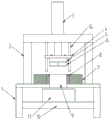
FIG. 1 is a schematic structural diagram of a preferred embodiment of the present invention;
FIG. 2 is a schematic structural view of a lower mold according to a preferred embodiment of the present invention;
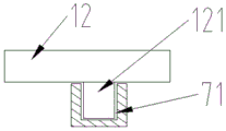
FIG. 3 is a schematic view of a positioning block and an adjusting groove in a preferred embodiment of the present invention;
in the figure: the device comprises a frame 1, a gantry frame 2, a punching cylinder 3, an upper cushion plate 4, an upper die fixing plate 5, an upper corner cutting die 6, a lower die fixing plate 7, a corner cutting female die 8, a discharge chute 9, a cross beam 10, a waste collecting box 11, a positioning block 12, a paperboard 13, a guide rod 14, an adjusting groove 71 and a sliding block 121.
Detailed Description
The present invention can be further described by the following embodiments, however, the scope of the present invention is not limited to the following embodiments.
Example 1: the corrugated board corner cutting device convenient for waste collection comprises a frame 1, a corner cutting die and a cutting cylinder 3, wherein a gantry frame 2 is arranged on the frame 1, and the cutting cylinder 3 with a downward output shaft is arranged at the top of the gantry frame 2;
the corner cutting die comprises an upper die and a lower die, the upper die comprises an upper base plate 4, an upper die fixing plate 5 and a corner cutting male die 6 which are sequentially fastened and connected from top to bottom, the upper surface of the upper base plate 4 is connected with the output end of a punching cylinder 3, the corner cutting male die 6 is of a square structure, the lower die comprises a lower die fixing plate 7 and a corner cutting female die 8, the corner cutting female die 8 is arranged in a female die cavity of the lower die fixing plate 7 and corresponds to the position under the corner cutting male die 6, the lower die fixing plate 7 is arranged on a frame 1,
the downward penetrability of chamfer die 8 and frame 1 has seted up blowpit 9, the lower part of frame 1 is equipped with crossbeam 10, is equipped with the garbage collection box 11 that corresponds blowpit 9 on the crossbeam 10, can effectively collect the edge cutting waste material through setting up garbage collection box 11.
Preferably, the lower die fixing plate 7 is provided with an adjustable corner cutting positioning mechanism, the corner cutting positioning mechanism comprises a positioning block 12, the positioning block is preferably a heavy iron block and is prevented from moving during positioning, a sliding block 121 is arranged at the lower part of the positioning block 12, and a square adjusting groove 71 matched with the sliding block 121 is arranged on the upper surface of the lower die fixing plate 7.
Preferably, guide rods 14 are respectively arranged on two sides of the bottom of the gantry frame 2, the guide rods 14 are in sliding connection with guide holes in two sides of the upper die fixing plate 5, a guide effect can be achieved by arranging a guide device, and cutting precision is improved.
The utility model discloses the working process:
remove the locating piece and adjust the position of locating piece 12, the cardboard 13 that will wait to cut is put on lower die fixing plate 7, and make the one end of cardboard lean on locating piece 12, thereby the length of cutting is well fixed a position, then with the cardboard push away to the edge of corner cut die 8 department and control the volume of pushing in, thereby control cutting width, after the location is accomplished, operating personnel opens die-cut cylinder 3, die-cut cylinder 3 drives the mould down, the cooperation of the outside blade of mould 6 on the corner cut and the inboard blade of corner cut die 8 is amputated the waste material, the waste material then directly gets into garbage collection box 11 through blowpit 9 and collects, after the die-cut is accomplished, thereby control die-cut cylinder 3 to reset and drive the mould and reset, can carry out the corner cut operation of next cardboard.
The basic principles and the main features of the invention and the advantages of the invention have been shown and described above, it will be evident to those skilled in the art that the invention is not limited to the details of the foregoing illustrative embodiments, but that the invention may be embodied in other specific forms without departing from the spirit or essential characteristics of the invention. The present embodiments are therefore to be considered in all respects as illustrative and not restrictive, the scope of the invention being indicated by the appended claims rather than by the foregoing description, and all changes which come within the meaning and range of equivalency of the claims are therefore intended to be embraced therein. Any reference sign in a claim should not be construed as limiting the claim concerned.
Furthermore, it should be understood that although the present description refers to embodiments, not every embodiment may contain only a single embodiment, and such description is for clarity only, and those skilled in the art should integrate the description, and the embodiments may be combined as appropriate to form other embodiments understood by those skilled in the art.
Claims (4)
1. A corrugated board corner cutting device convenient for waste collection comprises a rack (1), a corner cutting die and a punching cylinder (3), and is characterized in that a gantry frame (2) is arranged on the rack (1), and the punching cylinder (3) with an output shaft facing downwards is arranged at the top of the gantry frame (2);
the corner cutting die comprises an upper die and a lower die, the upper die comprises an upper base plate (4), an upper die fixing plate (5) and a corner cutting male die (6) which are sequentially fastened and connected from top to bottom, the upper surface of the upper base plate (4) is connected with the output end of a punching cylinder (3), the corner cutting male die (6) is of a square structure, the lower die comprises a lower die fixing plate (7) and a corner cutting female die (8), the corner cutting female die (8) is arranged in a female die cavity of the lower die fixing plate (7) and corresponds to the position under the corner cutting male die (6), the lower die fixing plate (7) is arranged on a rack (1),
the angle cutting die (8) and the rack (1) are provided with a discharge chute (9) in a downward penetrating manner, the lower portion of the rack (1) is provided with a cross beam (10), and a waste collecting box (11) corresponding to the discharge chute (9) is arranged on the cross beam (10).
2. A corrugated cardboard corner cutting device for facilitating the collection of waste material as claimed in claim 1 wherein the lower die fixing plate (7) is adjustably provided with a corner cutting positioning mechanism.
3. A corrugated cardboard corner cutting device for facilitating the collection of waste material as claimed in claim 2 wherein the corner cutting positioning mechanism comprises a positioning block (12), a sliding block (121) is provided at the lower part of the positioning block (12), and a square adjusting groove (71) matching with the sliding block (121) is provided at the upper surface of the lower die fixing plate (7).
4. A corrugated cardboard corner cutting device for facilitating the collection of waste material as claimed in claim 1 wherein the gantry frame (2) is provided with guide bars (14) on both sides of the bottom thereof, the guide bars (14) being slidably connected with the guide holes on both sides of the upper mold fixing plate (5).
Priority Applications (1)
| Application Number | Priority Date | Filing Date | Title |
|---|---|---|---|
| CN202022924101.1U CN213829311U (en) | 2020-12-09 | 2020-12-09 | Corrugated container board corner cut device convenient to garbage collection |
Applications Claiming Priority (1)
| Application Number | Priority Date | Filing Date | Title |
|---|---|---|---|
| CN202022924101.1U CN213829311U (en) | 2020-12-09 | 2020-12-09 | Corrugated container board corner cut device convenient to garbage collection |
Publications (1)
| Publication Number | Publication Date |
|---|---|
| CN213829311U true CN213829311U (en) | 2021-07-30 |
Family
ID=76996897
Family Applications (1)
| Application Number | Title | Priority Date | Filing Date |
|---|---|---|---|
| CN202022924101.1U Active CN213829311U (en) | 2020-12-09 | 2020-12-09 | Corrugated container board corner cut device convenient to garbage collection |
Country Status (1)
| Country | Link |
|---|---|
| CN (1) | CN213829311U (en) |
-
2020
- 2020-12-09 CN CN202022924101.1U patent/CN213829311U/en active Active
Similar Documents
| Publication | Publication Date | Title |
|---|---|---|
| CN202480440U (en) | Waste and hole clearing machine | |
| CN213829311U (en) | Corrugated container board corner cut device convenient to garbage collection | |
| CN219325307U (en) | Label waste material cleaning device that punches | |
| CN2327527Y (en) | Waste removing unit of slitter | |
| CN214871153U (en) | Production device for blanking and cutting of junction box and scrap separation | |
| CN212577263U (en) | Punching mechanism of numerical control punch | |
| CN210552306U (en) | Polyester bottle chip production facility | |
| CN220426526U (en) | Fixing structure for die machining | |
| CN209969706U (en) | Pendulum plate shearing machine | |
| CN212527997U (en) | Air pipe punching cutting machine | |
| CN217551902U (en) | Adjustable automatic deviation rectifying steel plate cutting machine | |
| CN213034049U (en) | Stamping and shearing die | |
| CN214238577U (en) | Double-station core rod guide pillar punching die | |
| CN215848678U (en) | Numerical control plank guillootine | |
| CN215702277U (en) | Punching processing tool for assembling template of catalyst module | |
| CN219446277U (en) | Carton production cross cutting machine | |
| CN218873437U (en) | Punching, cutting and forming die | |
| CN213256540U (en) | Die-cut edge of a knife mechanism of mould | |
| CN213104011U (en) | Stamping device with waste cutting function | |
| CN220161535U (en) | Cutting machine convenient to collect waste material | |
| CN211386493U (en) | Simple metal door plate punching and trimming equipment | |
| CN220826265U (en) | Injection molding processing device | |
| CN212525638U (en) | Automatic punching equipment | |
| CN213728823U (en) | Punching device for processing junction box | |
| CN214981476U (en) | Plastic bag perforating device capable of collecting waste materials under negative pressure |
Legal Events
| Date | Code | Title | Description |
|---|---|---|---|
| GR01 | Patent grant | ||
| GR01 | Patent grant |