CN213791861U - Dust collector for environmental protection refuse treatment - Google Patents
Dust collector for environmental protection refuse treatment Download PDFInfo
- Publication number
- CN213791861U CN213791861U CN202022285701.8U CN202022285701U CN213791861U CN 213791861 U CN213791861 U CN 213791861U CN 202022285701 U CN202022285701 U CN 202022285701U CN 213791861 U CN213791861 U CN 213791861U
- Authority
- CN
- China
- Prior art keywords
- box
- fixedly connected
- dust
- rubbish
- environmental protection
- Prior art date
- Legal status (The legal status is an assumption and is not a legal conclusion. Google has not performed a legal analysis and makes no representation as to the accuracy of the status listed.)
- Expired - Fee Related
Links
- 239000000428 dust Substances 0.000 title claims abstract description 45
- 230000007613 environmental effect Effects 0.000 title claims abstract description 12
- 239000010813 municipal solid waste Substances 0.000 claims abstract description 30
- XLYOFNOQVPJJNP-UHFFFAOYSA-N water Substances O XLYOFNOQVPJJNP-UHFFFAOYSA-N 0.000 claims description 28
- 239000007921 spray Substances 0.000 claims description 8
- 238000002347 injection Methods 0.000 claims description 4
- 239000007924 injection Substances 0.000 claims description 4
- 238000007789 sealing Methods 0.000 claims description 3
- 239000007858 starting material Substances 0.000 abstract 1
- 238000005192 partition Methods 0.000 description 6
- 230000000694 effects Effects 0.000 description 4
- 239000000463 material Substances 0.000 description 3
- 230000001681 protective effect Effects 0.000 description 2
- 206010019233 Headaches Diseases 0.000 description 1
- 230000004075 alteration Effects 0.000 description 1
- 230000009286 beneficial effect Effects 0.000 description 1
- 238000009414 blockwork Methods 0.000 description 1
- 238000002474 experimental method Methods 0.000 description 1
- 239000012530 fluid Substances 0.000 description 1
- 231100000869 headache Toxicity 0.000 description 1
- 238000012986 modification Methods 0.000 description 1
- 230000004048 modification Effects 0.000 description 1
- 239000007787 solid Substances 0.000 description 1
- 239000000243 solution Substances 0.000 description 1
- 238000006467 substitution reaction Methods 0.000 description 1
- 239000002699 waste material Substances 0.000 description 1
Images

Abstract
The utility model discloses an environmental protection is dust collector for refuse treatment, the power distribution box comprises a box body, the equal fixedly connected with crushing roller of inner chamber top middle-end of box, the right side fixedly connected with of box falls the dirt case, the right side below fixed mounting who falls the dirt case has the motor, the output fixedly connected with screw rod of motor, the left side below fixedly connected with loading board of box. The utility model discloses people drop into the inside of box with rubbish through the pan feeding mouth, start crushing roller work through external controller simultaneously, smash the back with rubbish through the crushing roller, accomodate rubbish through the containing box, through external controller starter motor work, it is rotatory to drive the screw rod through the motor, it drives the screw thread piece work through the screw rod, solved current rubbish when collecting, need use the dust device, beat wet back with rubbish and collect, but the rubbish surface after the dust fall is moist, the problem of people's collection is not convenient for.
Description
Technical Field
The utility model relates to a refuse treatment technical field specifically is an environmental protection dust collector for refuse treatment.
Background
The garbage is a waste product which loses use value and cannot be utilized, is an important link of material circulation, is not needed or useless solid and fluid materials, and is a headache problem in a big city with dense population.
SUMMERY OF THE UTILITY MODEL
An object of the utility model is to provide an environmental protection is dust collector for refuse treatment possesses the advantage of dust fall, has solved current rubbish and when collecting, needs to use dust device, drenches rubbish and collects, but the rubbish surface after the dust fall is moist, the problem that people of being not convenient for collected.
In order to achieve the above object, the utility model provides a following technical scheme: the utility model provides an environmental protection is dust collector for refuse treatment, includes the box, the equal fixedly connected with crushing roller of inner chamber top middle-end of box, the right side fixedly connected with of box falls the dirt case, the right side below fixed mounting who falls the dirt case has the motor, the output fixedly connected with screw rod of motor, the left side below fixedly connected with loading board of box, the left end swing joint of screw rod is in the right side of loading board, the surperficial threaded connection of screw rod has the thread piece, the top fixedly connected with containing box of thread piece, the top fixed mounting who falls the dirt case has the pump machine, the output fixedly connected with water tank of pump machine, the bottom fixed connection of water tank is in the top right-hand member of box.
Preferably, the left side sliding connection of box has the baffle, the top fixedly connected with pull rod of baffle, the spout has been seted up to the left side top of box, the right side sliding connection of pull rod is in the inner chamber of spout, the left side middle-end fixedly connected with stopper of box, the inboard sliding connection of stopper is in the surface of baffle.
Preferably, the top middle end of the box body is fixedly connected with a feeding port, the inner side of the inner cavity of the box body is fixedly connected with a protection block, and the surface of the crushing roller is connected in the inner cavity of the protection block in a sliding manner.
Preferably, the output end of the pump is fixedly connected with a spray head, the top of the inner cavity of the water tank is fixedly connected with a water filling port, and the surface of the water filling port is in threaded connection with a sealing cover.
Preferably, the bottom of box and the equal fixedly connected with supporting leg in bottom of dust fall case, the quantity of supporting leg is four, and evenly distributed both ends around box and dust fall bottom of the case portion.
Compared with the prior art, the beneficial effects of the utility model are as follows:
1. the utility model discloses people throw rubbish into the inside of box through the pan feeding mouth, start crushing roller work through external controller simultaneously, after smashing rubbish through crushing roller, accomodate rubbish through the containing box, start motor work through external controller, drive the screw rod rotation through the motor, drive the screw block work through the screw rod, drive the containing box through the screw block and move right, move to the inside of dust fall case through the containing box, start pump machine work through external controller, pour into the water source to the inside of water tank through the water filling port, carry the water source to the shower nozzle through the pump machine, spray the dust fall by the shower nozzle again, carry the containing box to the loading board through the secondary work of motor, people mention the pull rod and take out the baffle, make the containing box reach the inside of loading board smoothly, dust fall and the effect of convenient collection have been reached, solved current rubbish when collecting, need use the dust device, wet the back with rubbish and collect, but the rubbish surface after the dust fall is moist, the problem that people of not being convenient for collected.
2. The utility model discloses a setting of baffle can seal the left side of box, avoids when carrying out the dust fall, and the dust wafts out in the left side of box, through the setting of crushing roller, can smash rubbish, improves the effect of dust fall, through the setting of shower nozzle, can not have the inside at the dust fall case at the dead angle and carry out the dust fall work.
Drawings
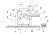
FIG. 1 is a front view of the structure of the present invention;
FIG. 2 is a sectional view of the structure of the present invention;
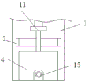
fig. 3 is a side view of the structure of the present invention.
In the figure: 1. a box body; 2. supporting legs; 3. a carrier plate; 4. a partition plate; 5. a limiting block; 6. a feeding port; 7. a water tank; 8. a pump machine; 9. a motor; 10. a dust falling box; 11. a pull rod; 12. a chute; 13. a water injection port; 14. a spray head; 15. a screw; 16. a thread block; 17. a storage box; 18. a crushing roller.
Detailed Description
The technical solutions in the embodiments of the present invention will be described clearly and completely with reference to the accompanying drawings in the embodiments of the present invention, and it is obvious that the described embodiments are only some embodiments of the present invention, not all embodiments. Based on the embodiments in the present invention, all other embodiments obtained by a person skilled in the art without creative work belong to the protection scope of the present invention.
In the description of the present invention, it should be noted that the terms "upper", "lower", "inner", "outer", "front end", "rear end", "both ends", "one end", "the other end", and the like indicate orientations or positional relationships based on the orientations or positional relationships shown in the drawings, and are only for convenience of description and simplification of description, but do not indicate or imply that the device or element to be referred must have a specific orientation, be constructed in a specific orientation, and be operated, and thus, should not be construed as limiting the present invention. Furthermore, the terms "first" and "second" are used for descriptive purposes only and are not to be construed as indicating or implying relative importance.
In the description of the present invention, it is to be noted that, unless otherwise explicitly specified or limited, the terms "mounted", "provided", "connected", and the like are to be construed broadly, such as "connected", which may be fixedly connected, detachably connected, or integrally connected; can be mechanically or electrically connected; they may be connected directly or indirectly through intervening media, or they may be interconnected between two elements. The specific meaning of the above terms in the present invention can be understood in specific cases to those skilled in the art.
The utility model discloses a box 1, supporting leg 2, loading board 3, baffle 4, stopper 5, pan feeding mouth 6, water tank 7, pump machine 8, motor 9, dust fall case 10, pull rod 11, spout 12, water filling port 13, shower nozzle 14, screw rod 15, thread block 16, containing box 17 and 18 parts of crushing roller are the general standard or the part that technical staff in the field knows, and its structure and principle all are that this technical staff all can learn through the technical manual or learn through conventional experimental method.
Referring to fig. 1-3, a dust removing device for environmental protection garbage disposal comprises a box body 1, wherein the middle ends of the top of the inner cavity of the box body 1 are fixedly connected with crushing rollers 18, the right side of the box body 1 is fixedly connected with a dust falling box 10, a motor 9 is fixedly arranged below the right side of the dust falling box 10, the output end of the motor 9 is fixedly connected with a screw 15, the left side of the box body 1 is fixedly connected with a bearing plate 3, the left end of the screw 15 is movably connected to the right side of the bearing plate 3, the surface of the screw 15 is in threaded connection with a threaded block 16, the top of the threaded block 16 is fixedly connected with a containing box 17, the top of the dust falling box 10 is fixedly provided with a pump 8, the output end of the pump 8 is fixedly connected with a water tank 7, the bottom of the water tank 7 is fixedly connected to the right end of the top of the box body 1, the left side of the box body 1 is slidably connected with a partition plate 4, the top of the partition plate 4 is fixedly connected with a pull rod 11, a chute 12 is arranged above the left side of the box body 1, the right side of a pull rod 11 is connected in an inner cavity of a sliding groove 12 in a sliding manner, the middle end of the left side of a box body 1 is fixedly connected with a limiting block 5, the inner side of the limiting block 5 is connected on the surface of a partition plate 4 in a sliding manner, the middle end of the top of the box body 1 is fixedly connected with a feeding port 6, the inner side of the inner cavity of the box body 1 is fixedly connected with a protective block, the surface of a crushing roller 18 is connected in the inner cavity of the protective block in a sliding manner, the output end of a pump 8 is fixedly connected with a spray head 14, the top of the inner cavity of a water tank 7 is fixedly connected with a water filling port 13, the surface of the water filling port 13 is connected with a sealing cover in a threaded manner, the bottom of the box body 1 and the bottom of a dust-falling box 10 are respectively and fixedly connected with supporting legs 2, the number of the supporting legs 2 is four, the supporting legs are uniformly distributed at the front end and the back end of the bottoms of the box body 1 and the dust-falling box 10, the left side of the box body 1 can be sealed by the partition plate 4, dust-falling can be prevented from floating out when falling, due to the arrangement of the crushing roller 18, garbage can be crushed, the dust fall effect is improved, and due to the arrangement of the spray head 14, dust fall work can be performed in the dust fall box 10 without dead corners.
When the dust-reducing box is used, people put garbage into the box body 1 through the material inlet 6, the crushing roller 18 is started to work through the external controller, the garbage is crushed through the crushing roller 18, the garbage is stored through the storage box 17, the motor 9 is started to work through the external controller, the screw 15 is driven to rotate through the motor 9, the threaded block 16 is driven to work through the screw 15, the storage box 17 is driven to move rightwards through the threaded block 16, the garbage is moved into the dust-reducing box 10 through the storage box 17, the pump 8 is started to work through the external controller, a water source is injected into the water tank 7 through the water injection port 13, the water source is conveyed to the spray head 14 through the pump 8, the water source is sprayed through the spray head 14, the storage box 17 is conveyed to the bearing plate 3 through the secondary work of the dust-reducing motor 9, the pull rod 11 is lifted by people to take out the partition plate 4, so that the storage box 17 smoothly reaches the inside of the bearing plate 3, the effect of dust fall and convenient collection has been reached, has solved current rubbish and when collecting, need use dust device, drenches rubbish and collects, but rubbish surface after the dust fall is moist, the problem of people's collection of being not convenient for (external controller is the PLC controller in this application, and simultaneously, two wiring ends of external controller are connected with power plug through the wire, and adopt the commercial power to supply power in this application).
Although embodiments of the present invention have been shown and described, it will be appreciated by those skilled in the art that changes, modifications, substitutions and alterations can be made in these embodiments without departing from the principles and spirit of the invention, the scope of which is defined in the appended claims and their equivalents.
Claims (5)
1. The utility model provides an environmental protection is dust collector for refuse treatment, includes box (1), its characterized in that: the middle ends of the top parts of the inner cavities of the box bodies (1) are fixedly connected with crushing rollers (18), a dust falling box (10) is fixedly connected to the right side of the box body (1), a motor (9) is fixedly arranged below the right side of the dust falling box (10), the output end of the motor (9) is fixedly connected with a screw rod (15), the lower part of the left side of the box body (1) is fixedly connected with a bearing plate (3), the left end of the screw rod (15) is movably connected with the right side of the bearing plate (3), the surface of the screw rod (15) is in threaded connection with a thread block (16), the top of the thread block (16) is fixedly connected with a containing box (17), a pump (8) is fixedly arranged at the top of the dust falling box (10), the output end of the pump (8) is fixedly connected with a water tank (7), the bottom of the water tank (7) is fixedly connected to the right end of the top of the tank body (1).
2. The dust removing device for environmental protection garbage disposal according to claim 1, wherein: the left side sliding connection of box (1) has baffle (4), top fixedly connected with pull rod (11) of baffle (4), spout (12) have been seted up to the left side top of box (1), the right side sliding connection of pull rod (11) is in the inner chamber of spout (12), the left side middle-end fixedly connected with stopper (5) of box (1), the inboard sliding connection of stopper (5) is in the surface of baffle (4).
3. The dust removing device for environmental protection garbage disposal according to claim 1, wherein: the top middle end fixedly connected with pan feeding mouth (6) of box (1), the equal fixedly connected with protection piece of inner chamber inboard of box (1), the surperficial sliding connection of crushing roller (18) is in the inner chamber of protection piece.
4. The dust removing device for environmental protection garbage disposal according to claim 1, wherein: the output end of the pump (8) is fixedly connected with a spray head (14), the top of the inner cavity of the water tank (7) is fixedly connected with a water injection port (13), and the surface of the water injection port (13) is in threaded connection with a sealing cover.
5. The dust removing device for environmental protection garbage disposal according to claim 1, wherein: the equal fixedly connected with supporting leg (2) in bottom of the bottom of box (1) and dust fall case (10), the quantity of supporting leg (2) is four, and evenly distributed both ends around box (1) and dust fall case (10) bottom.
Priority Applications (1)
| Application Number | Priority Date | Filing Date | Title |
|---|---|---|---|
| CN202022285701.8U CN213791861U (en) | 2020-10-14 | 2020-10-14 | Dust collector for environmental protection refuse treatment |
Applications Claiming Priority (1)
| Application Number | Priority Date | Filing Date | Title |
|---|---|---|---|
| CN202022285701.8U CN213791861U (en) | 2020-10-14 | 2020-10-14 | Dust collector for environmental protection refuse treatment |
Publications (1)
| Publication Number | Publication Date |
|---|---|
| CN213791861U true CN213791861U (en) | 2021-07-27 |
Family
ID=76958157
Family Applications (1)
| Application Number | Title | Priority Date | Filing Date |
|---|---|---|---|
| CN202022285701.8U Expired - Fee Related CN213791861U (en) | 2020-10-14 | 2020-10-14 | Dust collector for environmental protection refuse treatment |
Country Status (1)
| Country | Link |
|---|---|
| CN (1) | CN213791861U (en) |
-
2020
- 2020-10-14 CN CN202022285701.8U patent/CN213791861U/en not_active Expired - Fee Related
Similar Documents
| Publication | Publication Date | Title |
|---|---|---|
| CN110293113B (en) | Energy-saving landfill leachate processing apparatus | |
| CN206395238U (en) | A kind of environmental protection dustbin | |
| CN213791861U (en) | Dust collector for environmental protection refuse treatment | |
| CN210012676U (en) | Kitchen waste oil purification treatment device | |
| CN110789880A (en) | Garbage can with in-situ garbage disposal function | |
| CN206825738U (en) | A kind of waste plastics cleaning device | |
| CN109179956A (en) | A kind of sludge dehydration device | |
| CN210993096U (en) | Meat amino acid ultrasonic-assisted separation and extraction equipment | |
| CN110152806A (en) | A kind of garbage treatment device | |
| CN212143876U (en) | High-efficient environment-friendly solid useless processing apparatus | |
| CN210031298U (en) | Wood pulp reducing mechanism is used in urine trousers production | |
| CN212288871U (en) | Garbage dehydration treatment device | |
| CN208340857U (en) | A kind of solid waste treatment facility | |
| CN213223636U (en) | High vacuum cleaning stove of stability | |
| CN214159767U (en) | Environment-friendly crushing and compressing device for garbage treatment | |
| CN211970569U (en) | Municipal administration rubbish compressor arrangement | |
| CN215514209U (en) | Cement charging devices of environmental protection | |
| CN220536567U (en) | Automatic garbage classification dustbin | |
| CN212449075U (en) | Easily abluent new forms of energy environmental protection formula garbage bin | |
| CN216996038U (en) | Municipal administration garbage bin belt cleaning device | |
| CN215791960U (en) | Compaction processing apparatus for environmental protection refuse treatment | |
| CN209720582U (en) | A kind of garbage disposal leakproofness has by force the transport device of sterilizing function | |
| CN208800486U (en) | A kind of cleaning device before camera lens, motor, optical filter box assembling | |
| CN213409788U (en) | High-efficient processing apparatus for useless processing admittedly | |
| CN210504133U (en) | Intelligent classification litterbin of convenient clearance |
Legal Events
| Date | Code | Title | Description |
|---|---|---|---|
| GR01 | Patent grant | ||
| GR01 | Patent grant | ||
| CF01 | Termination of patent right due to non-payment of annual fee | ||
| CF01 | Termination of patent right due to non-payment of annual fee |
Granted publication date: 20210727 |