CN213738467U - Construction auxiliary platform of afforestation engineering - Google Patents
Construction auxiliary platform of afforestation engineering Download PDFInfo
- Publication number
- CN213738467U CN213738467U CN202022310567.2U CN202022310567U CN213738467U CN 213738467 U CN213738467 U CN 213738467U CN 202022310567 U CN202022310567 U CN 202022310567U CN 213738467 U CN213738467 U CN 213738467U
- Authority
- CN
- China
- Prior art keywords
- fixedly connected
- platform
- connecting rod
- sliding
- sliding groove
- Prior art date
- Legal status (The legal status is an assumption and is not a legal conclusion. Google has not performed a legal analysis and makes no representation as to the accuracy of the status listed.)
- Active
Links
Images
Abstract
The utility model discloses a afforestation engineering's construction auxiliary platform relates to afforestation technical field, and it includes the bottom plate, fixed surface is connected with the motor on the bottom plate, fixedly connected with gear two on the motor output shaft, two meshing of gear are connected with gear one, a gear fixed connection is on the steering column. This afforestation engineering's construction auxiliary platform, extend through control electric putter, electric putter drives two connecting rods and moves right along the notch when extending, drive slider one when two connecting rods move right and move right along spout one, two connecting rods promote the connecting rod one when moving right and rotate, drive the platform when connecting rod one rotates, it carries out work to have solved when utilizing the ladder to prune the gardener of being not convenient for, thereby gardener's work efficiency has been reduced, gardener's safety also can not obtain the problem of guarantee simultaneously.
Description
Technical Field
The utility model relates to an afforestation technical field specifically is a afforestation engineering's construction auxiliary platform.
Background
Landscaping is a beautiful natural environment and rest territory created by modifying terrains (or further building mountains, stacking stones, arranging water) to plant trees and flowers, building buildings, arranging gardens and paths and the like in a certain region by applying engineering technology and artistic means, and is called as a garden, the garden comprises a garden, a homestead, a small garden, a park, a botanical garden, an zoo and the like, and also comprises a forest park, a scenic spot, a natural protection area or a visiting area and a rest resort of a national park along with the development of landscaping subjects, the urban landscaping industry stably grows along with the continuous improvement of the urbanization rate, landscaping plants are usually trimmed by gardeners in the growing process, the gardeners usually trim higher greening plants by means of a ladder and are inconvenient for the gardeners to work when trimming by utilizing the ladder, thereby reducing the work efficiency of gardeners and ensuring the safety of gardeners.
SUMMERY OF THE UTILITY MODEL
Technical problem to be solved
Not enough to prior art, the utility model provides a construction auxiliary platform of afforestation engineering has solved and has been not convenient for gardener to carry out work when utilizing the ladder to prune to reduce gardener's work efficiency, gardener's safety also can not obtain the problem of guarantee simultaneously.
(II) technical scheme
In order to achieve the above purpose, the utility model adopts the technical proposal that: a construction auxiliary platform for landscaping engineering comprises a bottom plate, wherein a motor is fixedly connected to the upper surface of the bottom plate, a gear II is fixedly connected to an output shaft of the motor, the gear II is meshed with a gear I, the gear I is fixedly connected to a steering column, the bottom end of the steering column is movably connected to the upper surface of the bottom plate through a rolling bearing, the upper end of the steering column is fixedly connected to the bottom surface of a placing plate, support columns are fixedly connected to the left side and the right side of the bottom surface of the placing plate, the bottoms of the two support columns are respectively connected in an annular slide rail in a sliding manner, the annular slide rail is fixedly connected to the upper surface of the bottom plate, one end of an electric push rod is fixedly connected to the inner wall of the left side of the placing plate, the other end of the electric push rod is fixedly connected to a connecting rod II, the bottoms of the connecting rod II are connected in a sliding manner in a sliding groove V, and the sliding groove V is arranged on the inner wall of the lower side of the placing plate, the upper end of the second connecting rod penetrates through the notch and is connected to the bottom surface of the first sliding block, the notch is formed in the upper surface of the placing plate, the first sliding block is connected in the first sliding groove, the first sliding groove is formed in the bottom surface of the supporting rod, the bottom end of the supporting rod is connected to the right end of the upper surface of the placing plate, the upper end of the supporting rod is fixedly connected to the bottom surface of the platform, the rear surface of the supporting rod is fixedly connected with one end of the first connecting rod, the other end of the first connecting rod is fixedly connected to the front surface of the other supporting rod, the bottom end of the supporting rod is connected to the upper surface of the placing plate, the top end of the supporting rod is fixedly connected to the bottom surface of the platform, the right side surface of the second connecting rod is fixedly connected with a clamping plate, the inner wall of the right side of the clamping plate is provided with a third sliding groove, one end of the second sliding block is slidably connected to the third sliding groove, and the other end of the second sliding block is fixedly connected to the right side surface of the clamping block, joint piece bottom surface fixedly connected with spring one end, spring other end fixed connection is in the fixed slot bottom, the fixed slot is seted up on joint board downside inner wall, the joint board upper end is passed the joint board and is extended to the joint board outside, joint piece left surface articulates there is three one ends of connecting rod, three other ends of connecting rod are connected on three bottom surfaces of slider, three top sliding connection of slider are in four in the spout, the spout four-split is established on joint board upside inner wall, three left surface fixedly connected with rope one end of slider, the rope passes pulley, joint board and places board and swing joint on solid fixed ring, and solid fixed ring fixed connection is on the platform upper surface, pulley fixed connection is on joint board upside inner wall, place a plurality of teeth of board upside inner wall right side fixedly connected with.
Preferably, the bottom plate bottom surface four corners all fixedly connected with gyro wheel, four all be provided with the wheel on the gyro wheel and stop, bottom plate bottom surface middle part fixedly connected with battery, bottom plate left surface fixedly connected with drags the pendant, fixed surface is connected with the staircase before the platform.
Preferably, equal fixedly connected with guardrail all around on the platform upper surface, front side the guardrail has the dodge gate through hinge swing joint, the dodge gate left end has connecting plate one end through round pin axle swing joint, connecting plate other end bottom surface fixedly connected with card axle one end, card axle other end swing joint is in a card section of thick bamboo, a card section of thick bamboo fixed connection is on left side guardrail front surface.
Preferably, the upper surface of the platform is provided with a second sliding groove, the second sliding groove is connected with a storage box in a sliding mode, and the front surface of the storage box is fixedly connected with a handle.
Preferably, the electric push rod and the motor are provided with adaptive wireless controllers, a receiving end adaptive to the wireless controller is arranged in the storage battery, the input end of the receiving end is electrically connected with the output end of the storage battery, and the output end of the receiving end is electrically connected with the input ends of the motor and the electric push rod respectively.
Preferably, the first sliding groove, the second sliding groove, the third sliding groove and the fourth sliding groove are all T-shaped sliding grooves, and the first sliding block, the second sliding block and the third sliding block are all T-shaped sliding blocks.
(III) advantageous effects
The beneficial effects of the utility model reside in that:
the construction auxiliary platform of the landscaping engineering drives the connecting rod two to move rightwards along the notch when the electric push rod extends by controlling the extension of the electric push rod, drives the sliding block one to move rightwards along the sliding groove one when the connecting rod two moves rightwards, and pushes the connecting rod one to rotate when the connecting rod two moves rightwards, so that the connecting rod one drives the platform to lift when rotating, thereby facilitating a user to trim green plants with different heights by using the device, further facilitating the user to improve the working efficiency of gardeners by using the device, avoiding the worker from being injured due to the falling of the constructor from the platform by arranging the guardrails around the platform, further improving the protection effect of the device on the constructor, and facilitating the user to fix the safety buckle on the body by arranging the fixing ring on the platform, thereby further improving the protection effect of the device on the constructor, taut and fix the rope on solid fixed ring through the user, it moves left along spout four to drive slider three when the rope is taut, three pulling joint pieces and slider two along three rebound movement of spout when the slider moves left through connecting rod three, the joint piece mesh with the tooth of placing on the board when rebound, the meshing of utilizing joint piece and tooth is connected and is fixed the platform position, thereby avoid the platform to receive gravity to drop when battery power is not enough or electric putter damages, and then further protection is advanced to constructor on the platform.
Drawings
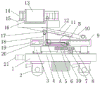
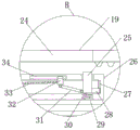
Fig. 1 is a schematic view of the front cross-sectional structure of the present invention;
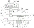
FIG. 2 is a schematic front view of the present invention;
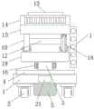
FIG. 3 is a left side view of the structure of the present invention;
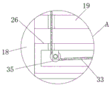
FIG. 4 is an enlarged schematic view of the structure of the present invention A;
FIG. 5 is an enlarged schematic view of the structure of the present invention B;
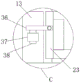
fig. 6 is a schematic diagram of the enlarged structure of the present invention C.
In the figure: the device comprises a base plate 1, rollers 2, support columns 3, annular sliding rails 4, a storage battery 5, a gear I6, a motor 7, a gear II 8, teeth 9, support rods 10, a chute I11, a connecting rod I12, a storage box 13, guardrails 14, a platform 15, a chute II 16, a slider I17, a connecting rod II 18, a placing plate 19, an electric push rod 20, a dragging and hanging piece 21, a staircase 22, a movable door 23, a notch 24, a clamping block 25, a clamping plate 26, a chute III 27, a slider II 28, a spring 29, a fixing groove 30, a connecting rod III 31, a slider III 32, a rope 33, a chute IV 34, a pulley 35, a connecting plate 36, a clamping cylinder 37, a clamping shaft 38 and a steering column 39.
Detailed Description
The technical solutions in the embodiments of the present invention will be described clearly and completely with reference to the accompanying drawings in the embodiments of the present invention, and it is obvious that the described embodiments are only some embodiments of the present invention, not all embodiments. Based on the embodiments in the present invention, all other embodiments obtained by a person skilled in the art without creative work belong to the protection scope of the present invention.
As shown in fig. 1-6, the utility model provides a technical solution: a construction auxiliary platform 15 for landscaping engineering comprises a bottom plate 1, wherein a motor 7 is fixedly connected to the upper surface of the bottom plate 1, a second gear 8 is fixedly connected to an output shaft of the motor 7, the second gear 8 is connected with a first gear 6 in a meshing manner, the first gear 6 is fixedly connected to a steering column 39, the bottom end of the steering column 39 is movably connected to the upper surface of the bottom plate 1 through a rolling bearing, the motor 7 is controlled to work through a wireless controller, the output shaft of the motor 7 drives the second gear 8 to rotate when the motor 7 works, the steering column 39 is driven to rotate through meshing transmission when the second gear 8 rotates, so that a placing plate 19 and a platform 15 are driven to rotate by the rotation of the steering column 39, the position of the platform 15 is adjusted to facilitate the work of gardeners, the upper end of the steering column 39 is fixedly connected to the bottom surface of the placing plate 19, support columns 3 are fixedly connected to the left side and the right side of the bottom surface of the placing plate 19, the bottoms of the two support columns 3 are both slidably connected in an annular slide rail 4, when the placing plate 19 rotates, the supporting columns 3 on the left side and the right side are driven to rotate along the annular sliding rail 4, so that the placing plate 19 is further supported by the supporting columns 3 on the left side and the right side, and the stability of the device is further improved, the annular sliding rail 4 is fixedly connected to the upper surface of the bottom plate 1, one end of an electric push rod 20 is fixedly connected to the inner wall of the left side of the placing plate 19, the other end of the electric push rod 20 is fixedly connected with a connecting rod II 18, the bottom of the connecting rod II 18 is slidably connected into a chute V, the chute V is arranged on the inner wall of the lower side of the placing plate 19, the upper end of the connecting rod II 18 penetrates through a notch 24 and is connected to the bottom surface of a slider I17, the notch 24 is arranged on the upper surface of the placing plate 19, the slider I17 is slidably connected into a chute I11, the chute I11 is arranged on the bottom surface of the supporting rod 10, a user controls the electric push rod 20 to shrink through a wireless controller, the electric push rod 20 drives the connecting rod II 18 to move left and right along the notch 24 when shrinking, when the second connecting rod 18 moves left and right, the first sliding block 17 is driven to move along the first sliding groove 11, so that the second connecting rod 18 is driven to move up and down to drive the platform 15 to go up and down, the bottom end of the first connecting rod 10 is connected to the right end of the upper surface of the placing plate 19, the upper end of the first connecting rod 10 is fixedly connected to the bottom surface of the platform 15, the rear surface of the first connecting rod 12 is fixedly connected to one end of the rear connecting rod 12, the other end of the first connecting rod 12 is fixedly connected to the front surface of the other supporting rod 10, when the second connecting rod 18 pushes the front side supporting rod 10 to rotate up and down, the front side supporting rod 10 drives the rear side supporting rod 10 to synchronously rotate through the first connecting rod 12, meanwhile, the supporting rods 10 are arranged on the front side and the rear side of the placing plate 19, the bottom end of the rear side supporting rod 10 is connected to the upper surface of the placing plate 19, the top end of the rear side supporting rod 10 is fixedly connected to the bottom surface of the platform 15, a clamping plate 26 is fixedly connected to the right side face of the second connecting rod 18, a third sliding groove 27 is formed in the inner wall of the right side of the clamping plate 26, one end of a second sliding block 28 is connected in the third sliding groove 27 in a sliding mode, the other end of the second sliding block 28 is fixedly connected to the right side face of the clamping block 25, one end of a spring 29 is fixedly connected to the bottom face of the clamping block 25, the other end of the spring 29 is fixedly connected to the bottom of a fixing groove 30, the spring 29 is pulled to be stretched to generate tensile force when the clamping block 25 moves upwards, the clamping block 25 moves downwards under the tensile force of the spring 29 when a user releases the fixing of the rope 33, so that the clamping block 25 is separated from the teeth 9 to release the fixing of the platform 15, the fixing groove 30 is formed in the inner wall of the lower side of the clamping plate 26, the upper end of the clamping plate 26 penetrates through the clamping plate 26 and extends to the outer side of the clamping plate 26, one end of a third connecting rod 31 is hinged to the left side face of the clamping block 25, the other end of the third connecting rod is connected to the bottom face of the sliding block 32, the top end of a third sliding block 32 is connected in a fourth sliding groove 34 in a sliding manner, the fourth sliding groove 34 is arranged on the inner wall of the upper side of the clamping plate 26, one end of a rope 33 is fixedly connected to the left side face of the third sliding block 32, the rope 33 penetrates through a pulley 35, the clamping plate 26 and the placing plate 19 and is movably connected to a fixing ring, when a user adjusts the platform 15 to a proper height, the user tightens and fixes the rope 33 on the fixing ring, the rope 33 draws the third sliding block 32 to move leftwards along the fourth sliding groove 34, the third sliding block 32 drives the clamping block 25 to move upwards through a third connecting rod 31 when moving leftwards, the clamping block 25 draws a spring 29 to stretch and be meshed with the teeth 9 when moving upwards, so that the position of the platform 15 is fixed by the meshing of the clamping block 25 and the teeth 9, the fixing ring is fixedly connected to the upper surface of the platform 15, the pulley 35 is fixedly connected to the inner wall of the upper side of the clamping plate 26, and a plurality of teeth 9 are fixedly connected to the right side of the inner wall of the upper side of the placing plate 19, the four corners of the bottom surface of the bottom plate 1 are fixedly connected with idler wheels 2, the four idler wheels 2 are all provided with wheel brakes, the device can be fixed during construction by using the wheel brakes through arranging the wheel brakes on the idler wheels 2, so that the stability of the device is improved, the middle part of the bottom surface of the bottom plate 1 is fixedly connected with a storage battery 5, the left side surface of the bottom plate 1 is fixedly connected with a trailer 21, a user can conveniently use the trailer 21 to be connected with a trailer through arranging the trailer 21 so as to be convenient for the user to transport the device to different construction sites, the front surface of the platform 15 is fixedly connected with a staircase 22, the front surface of the platform 15 is provided with the staircase 22 so as to conveniently use the staircase 22 to go up and down the platform 15, so that the practicability of the device is improved, the guardrail 14 is fixedly connected around the upper surface of the platform 15, and the guardrail 14 is arranged around the platform 15 so as to prevent gardeners from falling off the platform 15 during the construction on the platform 15, further improving the protection effect of the device on gardeners, the front side guardrail 14 is movably connected with a movable door 23 through a hinge, the left end of the movable door 23 is movably connected with one end of a connecting plate 36 through a pin shaft, the bottom surface of the other end of the connecting plate 36 is fixedly connected with one end of a clamping shaft 38, the other end of the clamping shaft 38 is movably connected in a clamping cylinder 37, the gardeners can conveniently get in and out of the platform 15 through the arrangement of the movable door 23, meanwhile, the movable door 23 can be fixed through the connection of the clamping cylinder 37 and the clamping shaft 38, the clamping cylinder 37 is fixedly connected on the front surface of the left side guardrail 14, the upper surface of the platform 15 is provided with a second sliding groove 16, the second sliding groove 16 is internally and slidably connected with a storage box 13, the front surface of the storage box 13 is fixedly connected with a handle, the gardeners can conveniently store the trimmed, meanwhile, workers and pedestrians on the ground can be prevented from being injured by falling branches and leaves, the electric push rod 20 and the motor 7 are provided with wireless controllers matched with each other, receiving ends matched with the wireless controllers are arranged in the storage battery 5, the input ends of the receiving ends are electrically connected with the output ends of the storage battery 5, the output ends of the receiving ends are respectively electrically connected with the input ends of the motor 7 and the electric push rod 20, through the arrangement of the wireless controllers, the device is convenient for controlling the garden workers during construction on the platform 15, the practicability of the device is further improved, the first sliding groove 11, the second sliding groove 16, the third sliding groove 27 and the fourth sliding groove 34 are T-shaped sliding groove settings, and the first sliding block 17, the second sliding block 28 and the third sliding block 32 are T-shaped sliding block settings.
The utility model discloses an operating procedure does:
s1, when using the device, a user firstly uses the trailer 21 to connect the device with a trailer, then uses the trailer to transport the device to a construction site, after the device arrives at the construction site, the user uses the wheel brake to fix the roller, uses the staircase 22 to reach the platform 15, and fixes the safety belt on the body on the fixing ring, then the user closes the movable door 23, and rotates the connecting plate 36 to insert the clamping shaft 38 into the clamping cylinder 37 to fix the movable door 23, then the user uses the wireless controller to control the electric push rod 20 to extend, the electric push rod 20 simultaneously pushes the connecting rod two 18 to move rightwards along the notch 24, the connecting rod two 18 simultaneously moves rightwards along the sliding groove one 11, thereby the connecting rod one 12 is pushed to rotate upwards by the movement of the connecting rod two 18 and the sliding block one 17, and further the platform 15 is lifted upwards by the rotation of the connecting rod one 12, after the platform 15 rises to a proper height, a user enables the electric push rod 20 to stop extending through the controller, then the user draws the rope 33 on the fixing ring to be close and fixed, the rope 33 pulls the third slider 32 to move leftwards along the fourth sliding groove 34 while tightening, the third slider 32 drives the second clamping block 25 and the second slider 28 to move upwards along the third sliding groove 27 through the third connecting rod 31 while moving leftwards, the clamping block 25 pulls the spring 29 to extend while moving upwards, the top end of the clamping block 25 is meshed with the teeth 9 on the clamping plate 26, and therefore the platform 15 is fixed by means of meshing of the clamping block 25 and the teeth 9;
s2, a user stores the pruned branches and leaves in the storage box 13, when the user needs to adjust the angle of the platform 15, the user controls the motor 7 to work through the wireless controller, the output shaft of the motor 7 rotates to drive the gear II 8 to rotate when the motor 7 works, the gear II 8 drives the gear I6 to rotate through meshing, the gear I6 drives the steering column 39 to rotate when the gear I6 rotates, the steering column 39 drives the placing plate 19 to rotate when the steering column 39 rotates, the placing plate 19 rotates and simultaneously drives the supporting columns 3 on the left side and the right side to rotate along the annular sliding rail 4, meanwhile, the platform 15 is driven to rotate through the rotation of the placing plate 19, so as to adjust the position of the platform 15, when the user needs to unload the branches and leaves in the storage box 13, the user firstly releases the fixing of the rope 33 on the fixing ring, when the rope 33 is released, the clamping block 25 drives the sliding block II 28 to move downwards along the sliding groove III 27 under the tensile force of the spring 29, the clamping block 25 moves downwards and is separated from the teeth 9 on the placing plate 19, so that the position of the platform 15 is released from being fixed, then the electric push rod 20 is controlled to shrink by the user through the wireless controller, the first sliding block 17 and the second connecting rod 18 are driven to move leftwards along the first sliding groove 11 when the electric push rod 20 shrinks, so that the first connecting rod 12 rotates downwards, the platform 15 is lowered by the rotation of the first connecting rod 12, when the platform 15 descends to the lowest end, the user enables the electric push rod 20 to stop shrinking through the wireless controller, then the user rotates the connecting plate 36 to pull the clamping shaft 38 out of the clamping cylinder 37, at the moment, the user opens the movable door 23 and pulls the storage box 13 outwards along the second sliding groove 16 through a handle, and accordingly the trimmed branches and leaves are taken out.
The above-mentioned embodiments further describe the objects, technical solutions and advantages of the present invention in detail, it should be understood that the above description is only the embodiments of the present invention, and is not intended to limit the present invention, and any modifications, equivalent substitutions, improvements and the like made within the spirit and principle of the present invention should be included in the scope of the present invention.
Claims (6)
1. The utility model provides a construction auxiliary platform of afforestation engineering, includes bottom plate (1), its characterized in that: the upper surface of the bottom plate (1) is fixedly connected with a motor (7), an output shaft of the motor (7) is fixedly connected with a gear II (8), the gear II (8) is meshed with a gear I (6), the gear I (6) is fixedly connected onto a steering column (39), the bottom end of the steering column (39) is movably connected onto the upper surface of the bottom plate (1) through a rolling bearing, the upper end of the steering column (39) is fixedly connected onto the bottom surface of a placing plate (19), the left side and the right side of the bottom surface of the placing plate (19) are fixedly connected with supporting columns (3), the bottoms of the two supporting columns (3) are respectively connected into an annular sliding rail (4) in a sliding manner, the annular sliding rail (4) is fixedly connected onto the upper surface of the bottom plate (1), the inner wall of the left side of the placing plate (19) is fixedly connected with one end of an electric push rod (20), the other end of the electric push rod (20) is fixedly connected with a connecting rod II (18), the bottom of the second connecting rod (18) is connected in the fifth sliding groove in a sliding mode, the fifth sliding groove is formed in the inner wall of the lower side of the placing plate (19), the upper end of the second connecting rod (18) penetrates through the notch (24) and is connected to the bottom surface of the first sliding block (17), the notch (24) is formed in the upper surface of the placing plate (19), the first sliding block (17) is connected in the first sliding groove (11), the first sliding groove (11) is formed in the bottom surface of the supporting rod (10), the bottom end of the supporting rod (10) is connected to the right end of the upper surface of the placing plate (19), the upper end of the supporting rod (10) is fixedly connected to the bottom surface of the platform (15), one end of the first connecting rod (12) is fixedly connected to the rear surface of the supporting rod (10), the other end of the first connecting rod (12) is fixedly connected to the front surface of the other supporting rod (10), and the bottom end of the supporting rod (10) is connected to the upper surface of the placing plate (19), rear side the top end of bracing piece (10) is fixed connection on platform (15) bottom surface, connecting rod two (18) right flank is fixed connection with joint board (26), joint board (26) right side inner wall has seted up spout three (27), sliding connection has slider two (28) one end in spout three (27), slider two (28) other end is fixed connection on joint piece (25) right flank, joint piece (25) bottom surface is fixed connection with spring (29) one end, spring (29) other end is fixed connection in fixed slot (30) bottom, fixed slot (30) are seted up on joint board (26) downside inner wall, joint board (26) upper end is passed joint board (26) and is extended to the joint board (26) outside, joint piece (25) left flank articulates there is connecting rod three (31) one end, connecting rod three (31) other end is connected on slider three (32) bottom surface, three (32) top sliding connection of slider is in four (34) in the spout, four (34) in the spout are seted up on joint board (26) upside inner wall, three (32) left side fixedly connected with rope (33) one end of slider, rope (33) pass pulley (35), joint board (26) and place board (19) and swing joint on solid fixed ring, and solid fixed ring fixed connection is on platform (15) upper surface, pulley (35) fixed connection is on joint board (26) upside inner wall, place a plurality of teeth (9) of board (19) upside inner wall right side fixedly connected with.
2. The construction auxiliary platform for landscaping engineering according to claim 1, wherein: bottom plate (1) bottom surface four corners department equal fixedly connected with gyro wheel (2), four all be provided with the wheel on gyro wheel (2) and stop, bottom plate (1) bottom surface middle part fixedly connected with battery (5), bottom plate (1) left side fixedly connected with drags pendant (21), fixed surface is connected with staircase (22) before platform (15).
3. The construction auxiliary platform for landscaping engineering according to claim 1, wherein: equal fixedly connected with guardrail (14), front side all around on platform (15) upper surface guardrail (14) have dodge gate (23) through hinge swing joint, dodge gate (23) left end has connecting plate (36) one end through round pin axle swing joint, connecting plate (36) other end bottom surface fixedly connected with card axle (38) one end, card axle (38) other end swing joint is in a card section of thick bamboo (37), a card section of thick bamboo (37) fixed connection is on left side guardrail (14) front surface.
4. The construction auxiliary platform for landscaping engineering according to claim 1, wherein: the utility model discloses a storage cabinet, including platform (15), spout two (16) have been seted up to platform (15) upper surface, and sliding connection has bin (13) in spout two (16), bin (13) front surface fixed connection has the handle.
5. The construction auxiliary platform for landscaping engineering according to claim 2, wherein: the electric push rod (20) and the motor (7) are provided with wireless controllers matched with each other, a receiving end matched with the wireless controllers is arranged in the storage battery (5), the input end of the receiving end is electrically connected with the output end of the storage battery (5), and the output end of the receiving end is electrically connected with the input ends of the motor (7) and the electric push rod (20) respectively.
6. The construction auxiliary platform for landscaping engineering according to claim 1, wherein: the first sliding groove (11), the second sliding groove (16), the third sliding groove (27) and the fourth sliding groove (34) are all T-shaped sliding groove arrangements, and the first sliding block (17), the second sliding block (28) and the third sliding block (32) are all T-shaped sliding block arrangements.
Priority Applications (1)
| Application Number | Priority Date | Filing Date | Title |
|---|---|---|---|
| CN202022310567.2U CN213738467U (en) | 2020-10-16 | 2020-10-16 | Construction auxiliary platform of afforestation engineering |
Applications Claiming Priority (1)
| Application Number | Priority Date | Filing Date | Title |
|---|---|---|---|
| CN202022310567.2U CN213738467U (en) | 2020-10-16 | 2020-10-16 | Construction auxiliary platform of afforestation engineering |
Publications (1)
| Publication Number | Publication Date |
|---|---|
| CN213738467U true CN213738467U (en) | 2021-07-20 |
Family
ID=76851045
Family Applications (1)
| Application Number | Title | Priority Date | Filing Date |
|---|---|---|---|
| CN202022310567.2U Active CN213738467U (en) | 2020-10-16 | 2020-10-16 | Construction auxiliary platform of afforestation engineering |
Country Status (1)
| Country | Link |
|---|---|
| CN (1) | CN213738467U (en) |
Cited By (1)
| Publication number | Priority date | Publication date | Assignee | Title |
|---|---|---|---|---|
| CN114751342A (en) * | 2022-03-08 | 2022-07-15 | 徐州市九州生态园林股份有限公司 | Auxiliary device for mountain slope treatment greening construction and using method thereof |
-
2020
- 2020-10-16 CN CN202022310567.2U patent/CN213738467U/en active Active
Cited By (2)
| Publication number | Priority date | Publication date | Assignee | Title |
|---|---|---|---|---|
| CN114751342A (en) * | 2022-03-08 | 2022-07-15 | 徐州市九州生态园林股份有限公司 | Auxiliary device for mountain slope treatment greening construction and using method thereof |
| CN114751342B (en) * | 2022-03-08 | 2023-09-15 | 徐州市九州生态园林股份有限公司 | Auxiliary device for mountain body treatment slope greening construction and application method thereof |
Similar Documents
| Publication | Publication Date | Title |
|---|---|---|
| CN107926596A (en) | A kind of ornamental and afforestation trees planting unit easy to remove | |
| CN105197849A (en) | Multifunctional rail operating car for greenhouse | |
| CN101401538B (en) | Tree trimmer for high and large gardens | |
| CN201290279Y (en) | High big garden-trees trimming machine | |
| CN208258550U (en) | A kind of gardens gardening is with climbing rattan teapoy | |
| CN213738467U (en) | Construction auxiliary platform of afforestation engineering | |
| CN102349369A (en) | Paddy field general walking device | |
| CN112293082A (en) | Tree high branch trimming device for landscaping | |
| CN209398340U (en) | A kind of removable garden ladder | |
| CN213343295U (en) | Municipal afforestation is with planting auxiliary device | |
| CN206978134U (en) | A kind of tree trimming moulding machine | |
| CN214853171U (en) | Greenhouse rolling device for agricultural engineering | |
| CN113796179A (en) | Seedling transplanting device and method | |
| CN206737807U (en) | One planting fruit-trees packaged type automatic lifting trimming ladder | |
| CN214347101U (en) | Gardens are built with branch rubbing crusher structure that falls | |
| CN202178947U (en) | General running gear for paddy field | |
| CN210053834U (en) | Grass planting device for landscaping | |
| CN205011337U (en) | Greenhouse is with multi -functional track operation car | |
| CN206808020U (en) | A kind of planting tree pit-picker | |
| CN203912677U (en) | Electronic pair of saw trimmer of a kind of orbital motion | |
| CN215558811U (en) | A lift platform is pruned to trees for afforestation construction | |
| CN215012220U (en) | Tree planting equipment for garden construction | |
| CN214545837U (en) | Multi-functional trimming machine in gardens that facilitates use | |
| CN220799200U (en) | Portable ornamental trees and shrubs trimming means | |
| CN220564244U (en) | Lifting device for garden trimming |
Legal Events
| Date | Code | Title | Description |
|---|---|---|---|
| GR01 | Patent grant | ||
| GR01 | Patent grant |