CN213722040U - Image diagnostic instrument for radiology department - Google Patents
Image diagnostic instrument for radiology department Download PDFInfo
- Publication number
- CN213722040U CN213722040U CN202021796959.8U CN202021796959U CN213722040U CN 213722040 U CN213722040 U CN 213722040U CN 202021796959 U CN202021796959 U CN 202021796959U CN 213722040 U CN213722040 U CN 213722040U
- Authority
- CN
- China
- Prior art keywords
- mounting
- outer side
- piece
- main body
- rod
- Prior art date
- Legal status (The legal status is an assumption and is not a legal conclusion. Google has not performed a legal analysis and makes no representation as to the accuracy of the status listed.)
- Expired - Fee Related
Links
Images


Abstract
The utility model discloses a radiological imaging diagnostic apparatus, which comprises a fixed seat, wherein one side of the fixed seat is connected with an operating platform through a connecting wire, the bottom of the operating platform is fixed with an installation rod, the outer side of the installation rod is provided with a supporting mechanism, the outer side of the fixed seat is provided with a mounting rack, the outer side of the mounting rack is provided with an imaging diagnosis mechanism main body, and one side of the mounting rack is provided with a wire bundling mechanism; the utility model can conveniently remove the fixation between the mounting rod and the supporting leg main body through the arrangement of the supporting mechanism, and can conveniently replace the supporting mechanism, thereby achieving the effect of easily replacing the supporting leg main body; the utility model discloses can be through the setting of bunch mechanism, can be convenient install the bunch piece, bunch piece this moment can carry on spacingly to the connecting wire in the image diagnosis mechanism main part outside, avoids the connecting wire to scatter at will and the problem of unaesthetic, and it is comparatively simple and convenient to use.
Description
Technical Field
The utility model belongs to the technical field of medical equipment, concretely relates to image diagnostic apparatus for radiology department.
Background
The radiology department is an important auxiliary examination department of a hospital, is a department integrating examination, diagnosis and treatment, many diseases of clinical departments need to be clearly diagnosed and auxiliary diagnosed through radiology department equipment examination, the image diagnostic apparatus of the radiology department is one of necessary apparatuses for medical diagnosis of patients, effective medical image analysis can be provided, in the using process of the existing image diagnostic apparatus, the supporting legs at the bottom of an operating table are easy to be damaged or worn after being used for a long time, the height is easy to be uneven, and the supporting legs are difficult to replace, so that the radiology department image diagnostic apparatus is provided.
SUMMERY OF THE UTILITY MODEL
An object of the utility model is to provide a radiology department image diagnosis appearance to current image diagnosis appearance that proposes in solving above-mentioned background art is in the use, and the damaged or the condition of wearing and tearing appears easily in the supporting legs of operation panel bottom after long-time the use, and easy height is uneven and has the problem that the supporting legs is difficult for changing.
In order to achieve the above object, the utility model provides a following technical scheme: a radiology department image diagnostic apparatus comprises a fixed seat, wherein one side of the fixed seat is connected with an operating table through a connecting wire, the bottom of the operating table is fixedly provided with an installation rod, the outer side of the installation rod is provided with a supporting mechanism, the outer side of the fixed seat is provided with an installation frame, the outer side of the installation frame is provided with an image diagnostic mechanism main body, and one side of the installation frame is provided with a wire bundling mechanism;
the supporting mechanism comprises a supporting leg main body, the inside of the supporting leg main body is movably connected with a connecting rod extending to the outside, one end of the connecting rod is fixed with a handle block, the other end of the connecting rod is fixed with a mounting plate, a locking block is installed on the other side of the mounting plate, a limiting rod is arranged at the top and the bottom of the mounting plate, a movable block is installed at one end of the limiting rod, and one side of the mounting plate is connected with an extrusion spring.
Preferably, bunching mechanism is including bunching the line piece, one side of bunching the line piece is fixed with the installation piece, the top of installation piece is provided with the lock pad, the bottom of bunching the line piece is fixed with the connecting plate, the locating piece is installed to one side of connecting plate, the mounting hole has been seted up to the inside of connecting plate.
Preferably, a clamping groove is formed in the mounting frame, and a matching component is arranged between the clamping groove and the locking pad.
Preferably, the mounting rod is internally provided with a groove, and the size of the groove is matched with that of the locking block.
Preferably, the outer side of the handle block is provided with an arc-shaped groove, and the outer side of the handle block is provided with anti-skid lines.
Preferably, the supporting leg main part is internally provided with a placing groove, and the size of the placing groove is matched with the mounting rod.
Compared with the prior art, the beneficial effects of the utility model are that:
(1) the utility model discloses can be through supporting mechanism's setting, can be convenient remove the fixed between installation pole and the supporting legs main part to can be convenient change supporting mechanism, reached the effect of easily changing the supporting legs main part.
(2) The utility model discloses can be through the setting of bunch mechanism, can be convenient install the bunch piece, bunch piece this moment can carry on spacingly to the connecting wire in the image diagnosis mechanism main part outside, avoids the connecting wire to scatter at will and the problem of unaesthetic, and it is comparatively simple and convenient to use.
Drawings
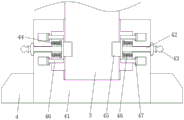
Fig. 1 is a schematic view of the overall structure of the present invention;
FIG. 2 is a schematic structural view of the supporting mechanism of the present invention;
fig. 3 is a schematic structural view of the wire bundling mechanism of the present invention;
in the figure: 1. a fixed seat; 2. an operation table; 3. mounting a rod; 4. a support mechanism; 41. a supporting leg main body; 42. a connecting rod; 43. a handle block; 44. mounting a plate; 45. locking the block; 46. a limiting rod; 47. a movable block; 48. a compression spring; 5. a mounting frame; 6. an image diagnosis mechanism main body; 7. a wire bundling mechanism; 71. a wire harness block; 72. mounting blocks; 73. a locking pad; 74. a connecting plate; 75. positioning blocks; 76. and (7) installing holes.
Detailed Description
The technical solutions in the embodiments of the present invention will be described clearly and completely with reference to the accompanying drawings in the embodiments of the present invention, and it is obvious that the described embodiments are only some embodiments of the present invention, not all embodiments. Based on the embodiments in the present invention, all other embodiments obtained by a person skilled in the art without creative work belong to the protection scope of the present invention.
Example 1
Referring to fig. 1-2, the present invention provides a technical solution: a radiology department image diagnostic apparatus comprises a fixed seat 1, wherein one side of the fixed seat 1 is connected with an operating table 2 through a connecting line, the bottom of the operating table 2 is fixedly provided with an installation rod 3, the outer side of the installation rod 3 is provided with a supporting mechanism 4, the outer side of the fixed seat 1 is provided with an installation frame 5, the outer side of the installation frame 5 is provided with an image diagnosis mechanism main body 6, and one side of the installation frame 5 is provided with a wire bundling mechanism 7;
the supporting mechanism 4 comprises a supporting leg main body 41, the inside of the supporting leg main body 41 is movably connected with a connecting rod 42 extending to the outside, one end of the connecting rod 42 is fixed with a handle block 43, the other end of the connecting rod 42 is fixed with a mounting plate 44, the other side of the mounting plate 44 is provided with a locking block 45, the top and the bottom of the mounting plate 44 are both provided with a limiting rod 46, one end of the limiting rod 46 is provided with a movable block 47, one side of the mounting plate 44 is connected with an extrusion spring 48, when the device is used, the device can be arranged through the supporting mechanism 4, when the supporting leg main body 41 is worn and needs to be replaced, an operator only needs to pull the handle block 43 outwards, at the moment, the handle block 43 can move along the horizontal direction of the connecting rod 42 with the handle, and can drive the mounting plate 44 to move simultaneously, and when the extrusion spring 48 is extruded, the locking block 45 on the other side of the mounting plate 44 can be driven to move, at this time, the locking block 45 can be disengaged from the inside of the mounting rod 3, so that the fixing between the mounting rod 3 and the supporting leg main body 41 is released, the supporting mechanism 4 can be conveniently replaced, the situation that the operating platform 2 is easily uneven due to the abrasion of the supporting leg main body 41 is avoided, and the effect of easily replacing the supporting leg main body 41 is achieved.
In this embodiment, it is preferable that the inside of the mounting rod 3 is provided with a groove, and the size of the groove is matched with the size of the dead lock block 45.
In this embodiment, preferably, the outer side of the handle block 43 is provided with an arc-shaped groove, and the outer side of the handle block 43 is provided with an anti-slip pattern.
In this embodiment, it is preferable that a placement groove is provided inside the supporting leg main body 41, and the size of the placement groove is adapted to the mounting rod 3.
Example 2
Referring to fig. 1-3, the present invention provides a technical solution: a radiology department image diagnostic apparatus comprises a fixed seat 1, wherein one side of the fixed seat 1 is connected with an operating table 2 through a connecting line, the bottom of the operating table 2 is fixedly provided with an installation rod 3, the outer side of the installation rod 3 is provided with a supporting mechanism 4, the outer side of the fixed seat 1 is provided with an installation frame 5, the outer side of the installation frame 5 is provided with an image diagnosis mechanism main body 6, and one side of the installation frame 5 is provided with a wire bundling mechanism 7;
the supporting mechanism 4 comprises a supporting leg main body 41, the inside of the supporting leg main body 41 is movably connected with a connecting rod 42 extending to the outside, one end of the connecting rod 42 is fixed with a handle block 43, the other end of the connecting rod 42 is fixed with a mounting plate 44, the other side of the mounting plate 44 is provided with a locking block 45, the top and the bottom of the mounting plate 44 are both provided with a limiting rod 46, one end of the limiting rod 46 is provided with a movable block 47, one side of the mounting plate 44 is connected with an extrusion spring 48, when the device is used, the supporting leg main body 41 can be replaced after being worn through the arrangement of the supporting mechanism 4, an operator only needs to pull the handle block 43 outwards, at the moment, the handle block 43 can move along the horizontal direction of the connecting rod 42 and can drive the mounting plate 44 to move simultaneously, and when the extrusion spring 48 is extruded, the locking block 45 at the other side of the mounting plate 44 can be driven to move, at this time, the locking block 45 can be disengaged from the inside of the mounting rod 3, so that the fixing between the mounting rod 3 and the supporting leg main body 41 is released, the supporting mechanism 4 can be conveniently replaced, the situation that the operating platform 2 is easily uneven due to the abrasion of the supporting leg main body 41 is avoided, and the effect of easily replacing the supporting leg main body 41 is achieved.
In this embodiment, preferably, the wire bundling mechanism 7 includes a wire bundling block 71, a mounting block 72 is fixed on one side of the wire bundling block 71, a locking pad 73 is disposed on the top of the mounting block 72, a connecting plate 74 is fixed on the bottom of the wire bundling block 71, a positioning block 75 is mounted on one side of the connecting plate 74, a mounting hole 76 is formed in the connecting plate 74, during the use, an operator can insert the locking pad 73 into a corresponding slot of the mounting frame 5 by means of the installation of the wire bundling mechanism 7, at this time, the mounting block 72 can be inserted into the mounting frame 5 at the same time, and the connecting plate 74 on the outer side of the wire bundling block 71 can be moved at the same time, at this time, the positioning block 75 on the outer side of the connecting plate 74 can be inserted into the mounting frame 5, and finally, the bolt penetrates through the mounting hole 76 and is screwed into the mounting frame 5 to complete the fixation, so as to conveniently install the wire bundling block 71, at this time, the wire bundling block 71 can limit the connecting wire on the outer side of the image diagnosis mechanism main body 6, the problems of random scattering and unattractive appearance of the connecting wire are avoided, and the use is simple and convenient.
In this embodiment, preferably, a clamping groove is formed in the mounting frame 5, and a matching member is arranged between the clamping groove and the locking pad 73.
In this embodiment, it is preferable that the inside of the mounting rod 3 is provided with a groove, and the size of the groove is matched with the size of the dead lock block 45.
In this embodiment, preferably, the outer side of the handle block 43 is provided with an arc-shaped groove, and the outer side of the handle block 43 is provided with an anti-slip pattern.
In this embodiment, it is preferable that a placement groove is provided inside the supporting leg main body 41, and the size of the placement groove is adapted to the mounting rod 3.
The utility model discloses a theory of operation and use flow: when the device is used, the supporting mechanism 4 can be arranged, when the supporting leg main body 41 needs to be replaced after being worn, an operator only needs to pull the handle block 43 outwards, at the moment, the handle block 43 can move in the horizontal direction of the connecting rod 42 with a lock and can drive the mounting plate 44 to move simultaneously, the extrusion spring 48 is extruded, and meanwhile, the locking block 45 on the other side of the mounting plate 44 can be driven to move, at the moment, the locking block 45 can be separated from the inside of the mounting rod 3, so that the fixing between the mounting rod 3 and the supporting leg main body 41 is released, the supporting mechanism 4 can be conveniently replaced, the situation that the operating platform 2 is easy to be uneven due to the fact that the supporting leg main body 41 is worn is avoided, and the effect of easily replacing the supporting leg main body 41 is achieved; in the use, can be through the setting of bunch mechanism 7, the operator only needs to block dead pad 73 card and go into the draw-in groove that mounting bracket 5 corresponds, the inside of mounting bracket 5 can be gone into in the lump to installation piece 72 this moment, and make the connecting plate 74 in the bunch piece 71 outside can remove in the lump, the locating piece 75 in the connecting plate 74 outside can block inside mounting bracket 5 this moment, at last rethread bolt runs through mounting hole 76 and twists the inside completion of mounting bracket 5 fixed, thereby can be convenient install bunch piece 71, bunch piece 71 can carry on spacingly to the connecting wire in the image diagnosis mechanism main part 6 outside this moment, avoid the connecting wire to scatter at will and not beautiful problem, it is comparatively simple and convenient to use.
Although embodiments of the present invention have been shown and described, it will be appreciated by those skilled in the art that changes, modifications, substitutions and alterations can be made in these embodiments without departing from the principles and spirit of the invention, the scope of which is defined in the appended claims and their equivalents.
Claims (6)
1. The utility model provides a radiology department image diagnostic apparatus, includes fixing base (1), one side of fixing base (1) is connected with operation panel (2), its characterized in that through the connecting wire: a mounting rod (3) is fixed at the bottom of the operating table (2), a supporting mechanism (4) is arranged on the outer side of the mounting rod (3), a mounting frame (5) is arranged on the outer side of the fixing seat (1), an image diagnosis mechanism main body (6) is arranged on the outer side of the mounting frame (5), and a wire bundling mechanism (7) is arranged on one side of the mounting frame (5);
supporting mechanism (4) are including supporting legs main part (41), the inside swing joint of supporting legs main part (41) has connecting rod (42) that extends to the outside, the one end of connecting rod (42) is fixed with handle piece (43), the other end of connecting rod (42) is fixed with mounting panel (44), locking piece (45) are installed to the opposite side of mounting panel (44), the top and the bottom of mounting panel (44) all are provided with gag lever post (46), movable block (47) are installed to the one end of gag lever post (46), one side of mounting panel (44) is connected with extrusion spring (48).
2. A radiological image diagnosis apparatus according to claim 1, wherein: bunch mechanism (7) are including bunch piece (71), one side of bunch piece (71) is fixed with installation piece (72), the top of installation piece (72) is provided with lock pad (73), the bottom of bunch piece (71) is fixed with connecting plate (74), locating piece (75) are installed to one side of connecting plate (74), mounting hole (76) have been seted up to the inside of connecting plate (74).
3. A radiological image diagnosis apparatus according to claim 2, wherein: the inside of mounting bracket (5) has seted up the draw-in groove, be the cooperation component between draw-in groove and the dead pad (73) of lock.
4. A radiological image diagnosis apparatus according to claim 1, wherein: the inside of installation pole (3) is provided with the recess, the size of recess and the size adaptation of locking piece (45).
5. A radiological image diagnosis apparatus according to claim 1, wherein: the outer side of the handle block (43) is provided with an arc-shaped groove, and the outer side of the handle block (43) is provided with anti-skid grains.
6. A radiological image diagnosis apparatus according to claim 1, wherein: the supporting leg main body (41) is internally provided with a placing groove, and the size of the placing groove is matched with the mounting rod (3).
Priority Applications (1)
| Application Number | Priority Date | Filing Date | Title |
|---|---|---|---|
| CN202021796959.8U CN213722040U (en) | 2020-08-25 | 2020-08-25 | Image diagnostic instrument for radiology department |
Applications Claiming Priority (1)
| Application Number | Priority Date | Filing Date | Title |
|---|---|---|---|
| CN202021796959.8U CN213722040U (en) | 2020-08-25 | 2020-08-25 | Image diagnostic instrument for radiology department |
Publications (1)
| Publication Number | Publication Date |
|---|---|
| CN213722040U true CN213722040U (en) | 2021-07-20 |
Family
ID=76840525
Family Applications (1)
| Application Number | Title | Priority Date | Filing Date |
|---|---|---|---|
| CN202021796959.8U Expired - Fee Related CN213722040U (en) | 2020-08-25 | 2020-08-25 | Image diagnostic instrument for radiology department |
Country Status (1)
| Country | Link |
|---|---|
| CN (1) | CN213722040U (en) |
-
2020
- 2020-08-25 CN CN202021796959.8U patent/CN213722040U/en not_active Expired - Fee Related
Similar Documents
| Publication | Publication Date | Title |
|---|---|---|
| CN206120338U (en) | Novel dept. of radiology is fixed with head device | |
| CN213722040U (en) | Image diagnostic instrument for radiology department | |
| CN213759095U (en) | Anesthesia limb fixing device | |
| CN205862020U (en) | A kind of radiology department X-ray read tablet device | |
| CN215117011U (en) | Medical radiology department diagnosis viewing device | |
| CN212489945U (en) | Display device for obstetrical and gynecological delivery examination | |
| CN216167501U (en) | Head CT fixing and supporting device for radiology department | |
| CN213097950U (en) | Arm support frame for image examination | |
| CN111166596A (en) | Clinical diagnosis operation panel for gynecological pathology | |
| CN208426134U (en) | A kind of dept. of radiology's fixed platform | |
| CN215605729U (en) | A patient sample selective examination equipment for endocrinology department | |
| CN215899755U (en) | Thyroid tissue traction equipment for treatment | |
| CN214633396U (en) | Nerve evoked potential instrument | |
| CN220695500U (en) | Improved gynecological examination bed for vagina scrubbing | |
| CN219895774U (en) | Auxiliary fixing device | |
| CN214762090U (en) | Patient is recovered with walking support | |
| CN212997109U (en) | Special nursing bed of severe patient | |
| CN212989785U (en) | Film viewing lamp for radiology department | |
| CN217548723U (en) | Prevent that prone position that trachea cannula buckles from ventilating with fixing device | |
| CN214804793U (en) | Abdominal image diagnosis device for radiology department | |
| CN211934044U (en) | Children's nursing branch of academic or vocational study is with ECG monitor | |
| CN218870242U (en) | Support for endoscope | |
| CN217938622U (en) | Leg support frame for pregnant woman examination bed | |
| CN214906995U (en) | Novel arm blood sampling is with supplementary device | |
| CN211066689U (en) | Positioner for radiology department |
Legal Events
| Date | Code | Title | Description |
|---|---|---|---|
| GR01 | Patent grant | ||
| GR01 | Patent grant | ||
| CF01 | Termination of patent right due to non-payment of annual fee | ||
| CF01 | Termination of patent right due to non-payment of annual fee |
Granted publication date: 20210720 |