CN213646707U - Machining cutting device convenient to location - Google Patents
Machining cutting device convenient to location Download PDFInfo
- Publication number
- CN213646707U CN213646707U CN202022381162.8U CN202022381162U CN213646707U CN 213646707 U CN213646707 U CN 213646707U CN 202022381162 U CN202022381162 U CN 202022381162U CN 213646707 U CN213646707 U CN 213646707U
- Authority
- CN
- China
- Prior art keywords
- plate
- mounting
- connecting block
- clamping
- base plate
- Prior art date
- Legal status (The legal status is an assumption and is not a legal conclusion. Google has not performed a legal analysis and makes no representation as to the accuracy of the status listed.)
- Expired - Fee Related
Links
Images


Abstract
The utility model discloses a machining cutting device convenient for positioning, which comprises a first mechanism and a second mechanism, wherein the surface of the first mechanism is provided with the second mechanism, the lower end of a backing plate is fixedly provided with a support column, the support column is arranged on the upper surface of a base plate, both ends of a mounting plate are fixedly provided with an extension plate, one end of the extension plate is provided with a telescopic rod, one end of the telescopic rod is fixedly arranged on the outer surface of a clamping component, the surfaces of a fixed plate and a movable plate are respectively provided with the second mechanism, the clamping component is controlled by adjusting the telescopic rod, and then the plate to be cut is fixed by the clamping component, the plate is cut by a cutting mechanism after being arranged above the backing plate, thereby being convenient for rapidly positioning the plate, the motor drives a lead screw to rotate, the movable plate translates along the lead screw and the sliding rod, and further being convenient for adjusting, so as to adapt to plates with different sizes, thereby improving the flexibility of adjustment of the device.
Description
Technical Field
The utility model relates to a mechanical cutting equipment technical field specifically is a machining cutting device convenient to location.
Background
Machining refers to a process of changing the external dimensions or properties of a workpiece by a mechanical device, and is classified into cutting and pressing according to differences in machining modes, and a machine production process refers to a whole process of manufacturing a product from raw materials, and includes, for machine production, transportation and storage of raw materials, preparation for production, manufacturing of a blank, machining and heat treatment of parts, assembly and debugging of a product, painting, packaging, and the like.
The plate is in the in-process of carrying out machining, and the cutting is an indispensable process, but current cutting device mostly has the positioning action not enough, the flexibility of adjusting is relatively poor and the less problem of stationarity.
To the above problems, the existing device is improved, and the machining cutting device convenient to position is provided.
SUMMERY OF THE UTILITY MODEL
An object of the utility model is to provide a machining cutting device convenient to location adopts this device to work to the positioning action in having solved above-mentioned background is not enough, the relatively poor and less than problem of stationarity of the flexibility of regulation.
In order to achieve the above object, the utility model provides a following technical scheme: the utility model provides a machining cutting device convenient to location, includes first mechanism and second mechanism, and the surface of first mechanism is provided with the second mechanism, first mechanism includes bed plate, fixed plate, fly leaf, workstation and drive assembly, and the one end fixed mounting of bed plate has the fixed plate, and the other end of bed plate is provided with the fly leaf, and the upper surface at the bed plate is installed to the workstation, and drive assembly sets up in one side of workstation, and the bed plate passes through drive assembly to be connected with the fly leaf, second mechanism includes mounting panel, extension board, telescopic link, centre gripping subassembly and slip strip, and the equal fixed mounting in both ends of mounting panel has the extension board, and the one end of extension board is provided with the telescopic link, and the one end fixed mounting of telescopic link is on the surface of centre gripping subassembly, and slip strip fixed mounting is on the.
Further, the movable plate comprises an installation angle block and rolling wheels, the installation angle block is fixedly installed on each of two sides of the movable plate, the rolling wheels are arranged on one sides of the installation angle blocks, and the installation angle blocks are connected with the base plate through the rolling wheels.
Further, the workstation includes backing plate and support column, and the lower extreme fixed mounting of backing plate has the support column, and the support column setting is at the upper surface of bed plate.
Further, drive assembly includes first connecting block, the second connecting block, including a motor, an end cap, a controller, and a cover plate, lead screw and slide bar, first connecting block fixed mounting is at the upper surface of bed plate, the second connecting block sets up the one end at the bed plate, one side of second connecting block is provided with the motor, the one end setting of lead screw is on the surface of first connecting block, the other end of lead screw passes the second connecting block and is connected with the output of motor, the both sides of lead screw all are provided with the slide bar, the one end of slide bar is connected with the fixed surface of first connecting block, the fixed surface of the slide bar other end and second connecting block is connected, drive assembly passes through lead screw and slide bar and is connected with the fly leaf.
Furthermore, slide rail grooves are formed in vertical surfaces of two sides of the base plate and are connected with the rolling wheels.
Further, the centre gripping subassembly includes splint, presss from both sides tight strip and slider, and the fixed surface of splint installs and presss from both sides tight strip, and one side of splint is provided with the slider, and splint pass through the slider and are connected with the slider.
Further, the slider includes connecting rod and U type sliding sleeve, and the one end fixed mounting of connecting rod is provided with U type sliding sleeve in the other end of connecting rod in the one side of splint.
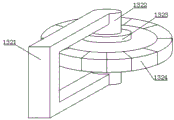
Further, the rolling wheel comprises a U-shaped mounting piece, a mounting column head, a rotary disc and a rotary wheel, the U-shaped mounting piece is fixedly mounted on one side of the mounting corner block, the mounting column head is fixedly mounted at two ends of the U-shaped mounting piece, the rotary disc is arranged at one end of the mounting column head, and the rotary disc is mounted on two sides of the rotary wheel.
Compared with the prior art, the beneficial effects of the utility model are as follows:
1. the utility model provides a machining cutting device convenient to location, the lower extreme fixed mounting of backing plate has the support column, the support column sets up the upper surface at the bed plate, the both ends of mounting panel are all fixed mounting has the extension board, the one end of extension board is provided with the telescopic link, the one end fixed mounting of telescopic link is on the surface of centre gripping subassembly, the surface of fixed plate and fly leaf all is provided with the second mechanism, control the centre gripping subassembly through adjusting the telescopic link, and then fix the panel that needs the cutting through the centre gripping subassembly, the panel is arranged in the top of backing plate after cutting it through cutting mechanism, thereby be convenient for quick location panel;
2. the utility model provides a machining cutting device convenient to location, first connecting block fixed mounting is on the upper surface of bed plate, the second connecting block sets up the one end at the bed plate, one side of second connecting block is provided with the motor, the one end of lead screw sets up the surface at first connecting block, the other end of lead screw passes through the second connecting block and is connected with the output of motor, the both sides of lead screw all are provided with the slide bar, the one end of slide bar is connected with the surface fixed of first connecting block, the slide bar other end is connected with the surface fixed of second connecting block, drive assembly passes through lead screw and slide bar and is connected with the fly leaf, drive the lead screw through the motor and rotate, the fly leaf translates along lead screw and slide bar, the distance between the fixed plate and the movable plate can be conveniently adjusted to adapt to plates with different sizes, so that the adjustment flexibility of the device is improved;
3. the utility model provides a machining cutting device convenient to location, the both sides of fly leaf are all fixed mounting with the installation hornblock, one side of installation hornblock is provided with the roll wheel, the installation hornblock is connected with the bed plate through the roll wheel, the both sides facade of bed plate has all been seted up the slide rail groove, the slide rail groove is connected with the roll wheel, U type installed part fixed mounting is in one side of installation hornblock, the both ends fixed mounting of U type installed part has the installation column cap, the one end of installation column cap is provided with the carousel, the carousel is installed in the both sides of runner, through the connection of carousel and slide rail groove, strengthen the limiting displacement of fly leaf both sides, and then improve the stationarity of fly leaf when the translation;
4. the utility model provides a machining cutting device convenient to location, one side of splint is provided with the slider, and splint pass through the slider and are connected with the sliding strip, and the one end fixed mounting of connecting rod is in one side of splint, and the other end of connecting rod is provided with U type sliding sleeve, and sliding strip fixed mounting drives the surface slip of U type sliding sleeve at the sliding strip through the centre gripping subassembly on the surface of mounting panel, strengthens the stationarity of centre gripping subassembly when reciprocating to promote the positioning action of centre gripping subassembly.
Drawings
Fig. 1 is a schematic view of the overall structure of the present invention;
fig. 2 is a schematic structural diagram of a first mechanism of the present invention;
fig. 3 is a schematic structural view of a second mechanism of the present invention;
FIG. 4 is a schematic structural view of the worktable and the driving assembly of the present invention;
FIG. 5 is a schematic structural view of the clamping assembly of the present invention;
fig. 6 is a schematic view of the rolling wheel structure of the present invention.
In the figure: 1. a first mechanism; 11. a base plate; 111. a slide rail groove; 12. a fixing plate; 13. a movable plate; 131. mounting a corner block; 132. a rolling wheel; 1321. a U-shaped mounting member; 1322. mounting a column head; 1323. a turntable; 1324. a rotating wheel; 14. a work table; 141. a base plate; 142. a support pillar; 15. a drive assembly; 151. a first connection block; 152. a second connecting block; 153. a motor; 154. a screw rod; 155. a slide bar; 2. a second mechanism; 21. mounting a plate; 22. an extension plate; 23. a telescopic rod; 24. a clamping assembly; 241. a splint; 242. a clamping bar; 243. a slider; 2431. a connecting rod; 2432. a U-shaped sliding sleeve; 25. a slide bar.
Detailed Description
The technical solutions in the embodiments of the present invention will be described clearly and completely with reference to the accompanying drawings in the embodiments of the present invention, and it is obvious that the described embodiments are only some embodiments of the present invention, not all embodiments. Based on the embodiments in the present invention, all other embodiments obtained by a person skilled in the art without creative work belong to the protection scope of the present invention.
Referring to fig. 1-6, a machining cutting device convenient for positioning includes a first mechanism 1 and a second mechanism 2, the second mechanism 2 is disposed on a surface of the first mechanism 1, the first mechanism 1 includes a base plate 11, a fixed plate 12, a movable plate 13, a worktable 14 and a driving assembly 15, the fixed plate 12 is fixedly mounted at one end of the base plate 11, the movable plate 13 is disposed at the other end of the base plate 11, the worktable 14 is mounted on an upper surface of the base plate 11, the driving assembly 15 is disposed at one side of the worktable 14, the base plate 11 is connected to the movable plate 13 through the driving assembly 15, the second mechanism 2 includes a mounting plate 21, an extension plate 22, a telescopic rod 23, a clamping assembly 24 and a sliding bar 25, the extension plate 22 is fixedly mounted at two ends of the mounting plate 21, the telescopic rod 23 is disposed at one end of the extension plate 22, one end of the telescopic rod 23 is fixedly mounted on an outer surface, slide bar 25 fixed mounting all is provided with second mechanism 2 on the surface of mounting panel 21, fixed plate 12 and movable plate 13, through adjusting telescopic link 23 control clamping component 24, and then fixes the panel that needs the cutting through clamping component 24, and panel cuts it through cutting mechanism behind the top of placing backing plate 141 in to be convenient for quick fix a position panel.
Referring to fig. 2-4, the movable plate 13 includes a mounting angle block 131 and a rolling wheel 132, the mounting angle block 131 is fixedly mounted on both sides of the movable plate 13, the rolling wheel 132 is disposed on one side of the mounting angle block 131, the mounting angle block 131 is connected to the base plate 11 through the rolling wheel 132, the worktable 14 includes a backing plate 141 and a supporting column 142, the supporting column 142 is fixedly mounted on a lower end of the backing plate 141, the supporting column 142 is disposed on an upper surface of the base plate 11, the driving assembly 15 includes a first connecting block 151, a second connecting block 152, a motor 153, a screw 154 and a sliding rod 155, the first connecting block 151 is fixedly mounted on the upper surface of the base plate 11, the second connecting block 152 is disposed at one end of the base plate 11, the motor 153 is disposed on one side of the second connecting block 152, one end of the screw 154 is disposed on a surface of the first connecting block 151, the other end of the screw 154 passes through, the both sides of lead screw 154 all are provided with slide bar 155, the one end of slide bar 155 and the fixed surface of first connecting block 151 are connected, the slide bar 155 other end is connected with the fixed surface of second connecting block 152, drive assembly 15 is connected with fly leaf 13 through lead screw 154 and slide bar 155, drive lead screw 154 through motor 153 and rotate, fly leaf 13 carries out the translation along lead screw 154 and slide bar 155, and then be convenient for adjust the distance between fixed plate 12 and the fly leaf 13, in order to adapt to the panel of different size of a dimension, thereby improve the flexibility that the device adjusted, slide rail groove 111 has all been seted up to the both sides facade of bed plate 11, slide rail groove 111 is connected with gyro wheel 132.
Referring to fig. 5 and 6, the clamping assembly 24 includes a clamping plate 241, a clamping bar 242 and a sliding member 243, the clamping bar 242 is fixedly installed on a surface of the clamping plate 241, the sliding member 243 is disposed on one side of the clamping plate 241, the clamping plate 241 is connected to the sliding bar 25 through the sliding member 243, the sliding member 243 includes a connecting rod 2431 and a U-shaped sliding sleeve 2432, one end of the connecting rod 2431 is fixedly installed on one side of the clamping plate 241, the other end of the connecting rod 2431 is provided with the U-shaped sliding sleeve 2432, the U-shaped sliding sleeve 2432 is driven by the clamping assembly 24 to slide on a surface of the sliding bar 25, so as to enhance the stability of the clamping assembly 24 during up and down movement and improve the positioning effect of the clamping assembly 24, the roller 132 includes a U-shaped mounting member 1321, a mounting post 1322, a rotating plate 1323 and a rotating wheel 1324, the U-shaped mounting member 1321 is fixedly installed on one side of, the turntables 1323 are installed on two sides of the rotating wheel 1324, and the limiting effect on two sides of the movable plate 13 is enhanced through the connection of the turntables 1323 and the slide rail grooves 111, so that the stability of the movable plate 13 during translation is improved.
In summary, the following steps: the utility model provides a machining cutting device convenient to location, the lower extreme fixed mounting of backing plate 141 has support column 142, support column 142 sets up the upper surface at bed plate 11, the equal fixed mounting in both ends of mounting panel 21 has extension board 22, the one end of extension board 22 is provided with telescopic link 23, the one end fixed mounting of telescopic link 23 is on the surface of clamping component 24, the surface of fixed plate 12 and fly leaf 13 all is provided with second mechanism 2, control clamping component 24 through adjusting telescopic link 23, and then fix the panel that needs the cutting through clamping component 24, the panel is placed above bed plate 141 after cutting through cutting mechanism, thereby be convenient for quick location panel, first connecting block 151 is fixed mounting at the upper surface of bed plate 11, second connecting block 152 sets up the one end at bed plate 11, one side of second connecting block 152 is provided with motor 153, one end of the screw rod 154 is arranged on the surface of the first connecting block 151, the other end of the screw rod 154 passes through the second connecting block 152 to be connected with the output end of the motor 153, both sides of the screw rod 154 are provided with a sliding rod 155, one end of the sliding rod 155 is fixedly connected with the surface of the first connecting block 151, the other end of the sliding rod 155 is fixedly connected with the surface of the second connecting block 152, the driving assembly 15 is connected with the movable plate 13 through the screw rod 154 and the sliding rod 155, the screw rod 154 is driven by the motor 153 to rotate, the movable plate 13 translates along the screw rod 154 and the sliding rod 155, and further the distance between the fixed plate 12 and the movable plate 13 is convenient to adjust so as to adapt to plates with different sizes, thereby improving the flexibility of adjustment of the device, both sides of the movable plate 13 are fixedly provided with the installation angle blocks 131, one side of the installation angle blocks 131 is provided with the rolling wheels, the vertical surfaces of two sides of the base plate 11 are both provided with a sliding rail groove 111, the sliding rail groove 111 is connected with a rolling wheel 132, a U-shaped mounting component 1321 is fixedly mounted on one side of the mounting corner block 131, mounting column heads 1322 are fixedly mounted on two ends of the U-shaped mounting component 1321, one end of the mounting column head 1322 is provided with a turntable 1323, the turntable 1323 is mounted on two sides of a rotating wheel 1324, the limiting effect of two sides of the movable plate 13 is enhanced through the connection of the turntable 1323 and the sliding rail groove 111, and further the stability of the movable plate 13 during translation is improved, one side of the clamping plate 241 is provided with a sliding piece 243, the clamping plate 241 is connected with a sliding strip 25 through the sliding piece 243, one end of a connecting rod 2431 is fixedly mounted on one side of the clamping plate 241, the other end of the connecting rod 2431 is provided with a U-shaped sliding sleeve 2432, the sliding strip 25 is fixedly mounted on the surface of the, thereby promoting the positioning of the clamping assembly 24.
It is noted that, herein, relational terms such as first and second, and the like may be used solely to distinguish one entity or action from another entity or action without necessarily requiring or implying any actual such relationship or order between such entities or actions. Also, the terms "comprises," "comprising," or any other variation thereof, are intended to cover a non-exclusive inclusion, such that a process, method, article, or apparatus that comprises a list of elements does not include only those elements but may include other elements not expressly listed or inherent to such process, method, article, or apparatus.
Although embodiments of the present invention have been shown and described, it will be appreciated by those skilled in the art that changes, modifications, substitutions and alterations can be made in these embodiments without departing from the principles and spirit of the invention, the scope of which is defined in the appended claims and their equivalents.
Claims (8)
1. The utility model provides a machining cutting device convenient to location, includes first mechanism (1) and second mechanism (2), the surface of first mechanism (1) is provided with second mechanism (2), its characterized in that: the first mechanism (1) comprises a base plate (11), a fixed plate (12), a movable plate (13), a workbench (14) and a driving assembly (15), wherein the fixed plate (12) is fixedly mounted at one end of the base plate (11), the movable plate (13) is arranged at the other end of the base plate (11), the workbench (14) is mounted on the upper surface of the base plate (11), the driving assembly (15) is arranged on one side of the workbench (14), and the base plate (11) is connected with the movable plate (13) through the driving assembly (15);
the second mechanism (2) comprises a mounting plate (21), an extension plate (22), a telescopic rod (23), a clamping assembly (24) and a sliding strip (25), the extension plate (22) is fixedly mounted at the two ends of the mounting plate (21), the telescopic rod (23) is arranged at one end of the extension plate (22), one end of the telescopic rod (23) is fixedly mounted on the outer surface of the clamping assembly (24), and the sliding strip (25) is fixedly mounted on the surface of the mounting plate (21).
2. A machine tool cutting assembly for facilitating positioning as claimed in claim 1 wherein: the movable plate (13) comprises mounting corner blocks (131) and rolling wheels (132), the mounting corner blocks (131) are fixedly mounted on two sides of the movable plate (13), the rolling wheels (132) are arranged on one sides of the mounting corner blocks (131), and the mounting corner blocks (131) are connected with the base plate (11) through the rolling wheels (132).
3. A machine tool cutting assembly for facilitating positioning as claimed in claim 1 wherein: workstation (14) include backing plate (141) and support column (142), and the lower extreme fixed mounting of backing plate (141) has support column (142), and support column (142) set up the upper surface at bed plate (11).
4. A machine tool cutting assembly for facilitating positioning as claimed in claim 1 wherein: the driving component (15) comprises a first connecting block (151) and a second connecting block (152), motor (153), lead screw (154) and slide bar (155), first connecting block (151) fixed mounting is at the upper surface of base plate (11), second connecting block (152) set up the one end in base plate (11), one side of second connecting block (152) is provided with motor (153), the one end setting of lead screw (154) is on the surface of first connecting block (151), the other end of lead screw (154) passes second connecting block (152) and is connected with the output of motor (153), the both sides of lead screw (154) all are provided with slide bar (155), the one end of slide bar (155) and the fixed surface of first connecting block (151) are connected, the fixed surface of the other end of slide bar (155) and second connecting block (152) is connected, drive assembly (15) are connected with fly leaf (13) through lead screw (154) and slide bar (155).
5. A machine tool cutting assembly for facilitating positioning as claimed in claim 1 wherein: slide rail grooves (111) are formed in the vertical surfaces of the two sides of the base plate (11), and the slide rail grooves (111) are connected with the rolling wheels (132).
6. A machine tool cutting assembly for facilitating positioning as claimed in claim 1 wherein: the clamping assembly (24) comprises a clamping plate (241), a clamping bar (242) and a sliding piece (243), the clamping bar (242) is fixedly installed on the surface of the clamping plate (241), the sliding piece (243) is arranged on one side of the clamping plate (241), and the clamping plate (241) is connected with the sliding bar (25) through the sliding piece (243).
7. A machine tool cutting assembly for facilitating positioning as claimed in claim 6 wherein: the sliding piece (243) comprises a connecting rod (2431) and a U-shaped sliding sleeve (2432), one end of the connecting rod (2431) is fixedly installed on one side of the clamping plate (241), and the other end of the connecting rod (2431) is provided with the U-shaped sliding sleeve (2432).
8. A machine tool cutting assembly for facilitating positioning as claimed in claim 2 wherein: the rolling wheel (132) comprises a U-shaped mounting piece (1321), a mounting column head (1322), a rotary disc (1323) and a rotary wheel (1324), the U-shaped mounting piece (1321) is fixedly mounted on one side of the mounting corner block (131), the mounting column head (1322) is fixedly mounted at two ends of the U-shaped mounting piece (1321), the rotary disc (1323) is arranged at one end of the mounting column head (1322), and the rotary disc (1323) is mounted on two sides of the rotary wheel (1324).
Priority Applications (1)
| Application Number | Priority Date | Filing Date | Title |
|---|---|---|---|
| CN202022381162.8U CN213646707U (en) | 2020-10-23 | 2020-10-23 | Machining cutting device convenient to location |
Applications Claiming Priority (1)
| Application Number | Priority Date | Filing Date | Title |
|---|---|---|---|
| CN202022381162.8U CN213646707U (en) | 2020-10-23 | 2020-10-23 | Machining cutting device convenient to location |
Publications (1)
| Publication Number | Publication Date |
|---|---|
| CN213646707U true CN213646707U (en) | 2021-07-09 |
Family
ID=76702915
Family Applications (1)
| Application Number | Title | Priority Date | Filing Date |
|---|---|---|---|
| CN202022381162.8U Expired - Fee Related CN213646707U (en) | 2020-10-23 | 2020-10-23 | Machining cutting device convenient to location |
Country Status (1)
| Country | Link |
|---|---|
| CN (1) | CN213646707U (en) |
-
2020
- 2020-10-23 CN CN202022381162.8U patent/CN213646707U/en not_active Expired - Fee Related
Similar Documents
| Publication | Publication Date | Title |
|---|---|---|
| CN110539370B (en) | High-efficiency full-automatic edge sealing machine and edge sealing method thereof | |
| CN112192769A (en) | Squaring machine silicon crystal bar clamping device | |
| CN213646707U (en) | Machining cutting device convenient to location | |
| CN217863500U (en) | Wood carving machine | |
| CN210936583U (en) | Automatic bending machine | |
| CN209503814U (en) | Four corner workpiece automatic chamfering lathes | |
| CN216442064U (en) | Material cutting device is used in production of frock clamp | |
| CN214350870U (en) | Turnover workbench | |
| CN113579352B (en) | Adjustable plate processing saw | |
| CN213317831U (en) | Drilling machine tool for die machining | |
| CN213829771U (en) | Squaring machine silicon crystal bar clamping device | |
| CN220313795U (en) | Cutting equipment for architectural decoration fitment engineering | |
| CN217072545U (en) | Dull and stereotyped two-way groover that induced drafts of paper support product | |
| CN215468523U (en) | Metal band sawing machine convenient to location | |
| CN220698302U (en) | Angle adjusting equipment for automobile frame machining | |
| CN216442082U (en) | High-efficient shaping machine | |
| CN216992144U (en) | Fixed-length double-end corner cutting machine for pressing line strips | |
| CN210081321U (en) | General assembly machine for bevel edge rounding | |
| CN212761350U (en) | Small angle processing device for aluminum profile | |
| CN216421225U (en) | Cutting device for plate processing | |
| CN218748278U (en) | Novel planer | |
| CN215431712U (en) | Special machine tool for milling groove | |
| CN219582251U (en) | Aluminum profile cutting device | |
| CN219853329U (en) | Combined clamp for machine tool | |
| CN215942071U (en) | A all-in-one for section bar processing |
Legal Events
| Date | Code | Title | Description |
|---|---|---|---|
| GR01 | Patent grant | ||
| GR01 | Patent grant | ||
| CF01 | Termination of patent right due to non-payment of annual fee | ||
| CF01 | Termination of patent right due to non-payment of annual fee |
Granted publication date: 20210709 Termination date: 20211023 |