CN213630302U - Buckle formula mounting structure of LED lens - Google Patents
Buckle formula mounting structure of LED lens Download PDFInfo
- Publication number
- CN213630302U CN213630302U CN202022828485.7U CN202022828485U CN213630302U CN 213630302 U CN213630302 U CN 213630302U CN 202022828485 U CN202022828485 U CN 202022828485U CN 213630302 U CN213630302 U CN 213630302U
- Authority
- CN
- China
- Prior art keywords
- hole
- fixed
- snap
- block
- mounting structure
- Prior art date
- Legal status (The legal status is an assumption and is not a legal conclusion. Google has not performed a legal analysis and makes no representation as to the accuracy of the status listed.)
- Active
Links
Images


Abstract
The utility model discloses a buckle formula mounting structure of LED lens, including aluminium base board, constant head tank, screw and first through-hole have been seted up at the top of aluminium base board, and the top welded mounting of constant head tank has fixed fixture block, and spacing hole and second through-hole have been seted up to the inboard bottom of fixed fixture block. Penetrate the LED wick through first through-hole and second through-hole, through the constant head tank, the screw is fixed the fixture block on aluminium base board with spacing hole, make the LED lamp pass through easily and fix on aluminium base board, make the accurate cover of fixed fixture block establish on the LED lamp, avoid causing the influence to the grading of LED lamp, and the sliding connection setting of cooperation slip buckle and slip draw-in groove and the magnetic attraction of magnetism piece are inhaled, with the laminating of inlaying of unsmooth piece, make firm the installing on fixed fixture block of lens, this device is simple structure not only, the flexible operation is convenient, and anti-seismic performance is strong, can reduce consuming time of assembly, and the production efficiency and the rate of utilization are improved.
Description
Technical Field
The utility model relates to a buckle installation technical field especially relates to a buckle formula mounting structure of LED lens.
Background
With the gradual development of LED lighting lamps, LED lamps are more and more popular with people, because the LED lamps have the advantages of high luminous purity, concentrated light beams, low power consumption and long service life, in public occasions such as lighting engineering auxiliary lighting and the like, the LED lighting lamps gradually replace some traditional light source products, the high controllability characteristic of the LED lighting lamps is exerted, the LED lighting lamps are wider and wider in application range from families to office buildings, roads to tunnels, automobiles to walking and auxiliary lighting to main lighting, and the LED lighting lamp system with intelligent control brings higher-level service to human beings.
In the production process of the LED lamp, the LED lens is usually adhered or adhered by using a glue dispenser, but the production assembly is long in work consumption, the waiting time for the solidification of the silica gel is long, the LED lens cannot be quickly assembled in the solidification process, the production line cannot quickly assemble the lamp, the slight displacement of the LED lens can be caused by the shrinkage of the silica gel in the solidification process, so that the light distribution of the LED lamp is influenced, in addition, the longer the silica gel is outdoors, the less the adhesive force is, the lower the anti-seismic property is, the LED lens falls off, and the use is influenced.
SUMMERY OF THE UTILITY MODEL
Not enough to prior art, the utility model provides a buckle formula mounting structure of LED lens has solved the problem that above-mentioned background art provided.
In order to achieve the above purpose, the utility model adopts the following technical scheme: a buckle type mounting structure of an LED lens comprises an aluminum substrate, wherein a positioning groove, a screw hole and a first through hole are formed in the top of the aluminum substrate, a fixed clamping block is welded and mounted at the top of the positioning groove, a limiting hole and a second through hole are formed in the bottom of the inner side of the fixed clamping block, the first through hole and the second through hole are consistent in size and are arranged in an up-and-down corresponding mode, a first groove is formed in the top of the fixed clamping block, a sliding clamping groove is formed in one side of the inner wall of the first groove, a fixed buckle is arranged in the sliding clamping groove and is in welded connection with the sliding clamping groove, a convex block is welded on one side wall of the fixed buckle, a second positive magnetic suction block is fixedly mounted on the other side wall of the convex block, a first positive magnetic suction block is fixedly mounted on the inner side wall of the fixed clamping block, a lens is placed at, the second groove is matched with the lug, a second negative magnetic attraction block is fixedly mounted on one side wall in the second groove, and a first negative magnetic attraction block is fixedly mounted on the outer side wall of the lens.
Preferably, the positioning groove, the screw hole and the first through hole are sequentially arranged from outside to inside, and the first through hole is located in the middle of the aluminum substrate.
Preferably, the fixed clamping block is arranged in a hollow mode, and an opening is formed in the top of the fixed clamping block.
Preferably, the positions of the limiting holes and the second through holes are sequentially arranged from outside to inside, and the number of the limiting holes is consistent with that of the screw holes and matched with the screw holes.
Preferably, the number of the first grooves is four and the first grooves are uniformly distributed on the fixed fixture block at equal intervals.
Preferably, the number of the sliding clamping grooves and the number of the fixed buckles are four groups and are arranged in a circular array.
Preferably, the width of the sliding buckle is consistent with the width of the first groove and is arranged for being attached to the first groove, the sliding buckle is matched with the sliding clamping groove, and the sliding buckle and the sliding clamping groove are arranged in a sliding connection mode.
Preferably, the number of the second negative magnetic attraction blocks is consistent with that of the second positive magnetic attraction blocks and is matched with the second positive magnetic attraction blocks.
Preferably, the first negative magnetic attraction block is positioned at two sides of the sliding buckle, and the first negative magnetic attraction block is matched with the first positive magnetic attraction block.
Compared with the prior art, the beneficial effects of the utility model are that: this buckle formula mounting structure of LED lens, penetrate the LED wick through first through-hole and second through-hole, through the constant head tank, the screw is fixed the fixture block on aluminium base board with spacing hole, make the LED lamp pass through easily and fix on aluminium base board, make the accurate cover of fixed fixture block establish on the LED lamp, avoid causing the influence to the grading of LED lamp, and the sliding connection setting of cooperation slip buckle and slip draw-in groove and the magnetic attraction of magnetism piece are inhaled, and the laminating of inlaying of unsmooth piece, make firm the installation on fixed fixture block of lens, this device simple structure, the flexible operation is convenient, and anti-seismic performance is strong, can reduce consuming time of assembly, and the production efficiency and the rate of utilization are improved.
Drawings
FIG. 1 is a schematic structural view of the present invention;
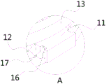
fig. 2 is a schematic diagram of a positional relationship of the second groove according to the present invention;
fig. 3 is an enlarged schematic view of the structure of part a of the present invention.
In the figure: the magnetic attraction type lens comprises an aluminum substrate 1, a positioning groove 2, a screw hole 3, a first through hole 4, a fixed clamping block 5, a sliding clamping groove 6, a second through hole 7, a limiting hole 8, a first groove 9, a first positive magnetic attraction block 10, a sliding buckle 11, a negative magnetic attraction block 12, a lens 13, a fixed buckle 14, a second positive magnetic attraction block 15, a second negative magnetic attraction block 16, a second groove 17 and a convex block 18.
Detailed Description
The technical solutions in the embodiments of the present invention will be described clearly and completely with reference to the accompanying drawings in the embodiments of the present invention, and it is obvious that the described embodiments are only some embodiments of the present invention, not all embodiments. Based on the embodiments in the present invention, all other embodiments obtained by a person skilled in the art without creative work belong to the protection scope of the present invention.
Referring to fig. 1-3, the present invention provides a technical solution: a buckle type mounting structure of an LED lens comprises an aluminum substrate 1, wherein the top of the aluminum substrate 1 is provided with a positioning groove 2, a screw hole 3 and a first through hole 4, the positions of the positioning groove 2, the screw hole 3 and the first through hole 4 are sequentially arranged from outside to inside, the first through hole 4 is positioned in the center of the aluminum substrate 1, the top of the positioning groove 2 is welded with a fixed clamping block 5, the fixed clamping block 5 is hollow, the top of the fixed clamping block 5 is provided with an opening, the bottom of the inner side of the fixed clamping block 5 is provided with a limiting hole 8 and a second through hole 7, the positions of the limiting hole 8 and the second through hole 7 are sequentially arranged from outside to inside, the number of the limiting holes 8 is consistent with the number of the screw holes 3 and is matched with the screw hole 3, the first through holes 4 and the second through holes 7 are consistent in size and are arranged in an up-down corresponding mode, the top of the fixed clamping block 5 is provided with first grooves, one side of the inner wall of the first groove 9 is provided with sliding clamping grooves 6, the sliding clamping grooves 6 are four groups and are arranged in a circular array, fixed buckles 14 are arranged in the sliding clamping grooves 6, the fixed buckles 14 are four groups and are arranged in a circular array, the fixed buckles 14 and the sliding clamping grooves 6 are arranged in a welding connection mode, a convex block 18 is welded on one side wall of each fixed buckle 14, a second positive magnetic suction block 15 is fixedly arranged on the other side wall of each convex block 18, a first positive magnetic suction block 10 is fixedly arranged on the inner side wall of each fixed clamping block 5, a lens 13 is arranged at the top of each fixed clamping block 5, the lens 13 is sleeved on each fixed clamping block 5, a sliding buckle 11 is welded on the outer side wall of each lens 13, the width of each sliding buckle 11 is consistent with the width of the first groove 9 and is arranged in a fit mode with the first groove 9, the sliding buckles 11 are matched with the, second recess 17 has been seted up to a lateral wall of slip buckle 11, second recess 17 and lug 18 phase-match, a inside lateral wall fixed mounting of second recess 17 has second negative magnetism to inhale piece 16, the quantity of second negative magnetism inhale piece 16 with the second positive magnetism inhale the quantity of piece 15 unanimous and inhale 15 phase-matches with the second positive magnetism, the lateral wall fixed mounting of lens 13 has first negative magnetism to inhale piece 12, first negative magnetism inhales piece 12 and is located the both sides of slip buckle 11, and first negative magnetism inhales piece 12 and first positive magnetism and inhales piece 10 phase-match.
The working principle is as follows: when the device needs to be installed, through the first through-hole 4 on the aluminium base board 1 and the second through-hole 7 on the fixed fixture block 5, penetrate and fix the LED wick on the fixed fixture block 5, cooperation constant head tank 2, screw 3 fixes the fixed fixture block 5 on aluminium base board 1 with spacing hole 8, attract through the magnetic force of first negative magnetic attraction block 12 and first positive magnetic attraction block 10 simultaneously, slide buckle 11 on the cooperation lens 13 lateral wall and the sliding connection setting of slide clamp groove 6, make slide buckle 11 along the inner wall lateral shifting of slide clamp groove 6 to fixed buckle 14, and through lug 18 and the positive magnetic attraction block 15 of second on the fixed buckle 14, cooperate second recess 17 and the negative magnetic attraction block 16 on the slide buckle 11, make slide buckle 11 and fixed buckle 14 fixed connection, accomplish the installation.
In conclusion, this buckle formula mounting structure of LED lens, penetrate the LED wick through first through-hole 4 and second through-hole 7, through constant head tank 2, screw 3 fixes fixed fixture block 5 on aluminium base board 1 with spacing hole 8, make the LED lamp pass through easily and fix on aluminium base board 1, make fixed fixture block 5 accurately cover and establish on the LED lamp, avoid causing the influence to the grading of LED lamp, and cooperate the sliding connection setting of slip buckle 11 and slip draw-in groove 6 and the magnetic attraction of magnetism piece, with the laminating of inlaying of unsmooth piece, make firm the installing on fixed fixture block 5 of lens 13, this device simple structure, the flexible operation is convenient, and anti-seismic performance is strong, can reduce consuming time of assembly, improve production efficiency and rate of use, the problem that above-mentioned background art provided has been solved.
It is noted that, herein, relational terms such as first and second, and the like may be used solely to distinguish one entity or action from another entity or action without necessarily requiring or implying any actual such relationship or order between such entities or actions. Also, the terms "comprises," "comprising," or any other variation thereof, are intended to cover a non-exclusive inclusion, such that a process, method, article, or apparatus that comprises a list of elements does not include only those elements but may include other elements not expressly listed or inherent to such process, method, article, or apparatus.
Although embodiments of the present invention have been shown and described, it will be appreciated by those skilled in the art that changes, modifications, substitutions and alterations can be made in these embodiments without departing from the principles and spirit of the invention, the scope of which is defined in the appended claims and their equivalents.
Claims (9)
1. A buckle type mounting structure of an LED lens comprises an aluminum substrate (1) and is characterized in that a positioning groove (2), a screw hole (3) and a first through hole (4) are formed in the top of the aluminum substrate (1), a fixed clamping block (5) is welded and mounted at the top of the positioning groove (2), a limiting hole (8) and a second through hole (7) are formed in the bottom of the inner side of the fixed clamping block (5), the first through hole (4) and the second through hole (7) are identical in size and are arranged in a vertically corresponding mode, a first groove (9) is formed in the top of the fixed clamping block (5), a sliding clamping groove (6) is formed in one side of the inner wall of the first groove (9), a fixed buckle (14) is arranged in the sliding clamping groove (6), the fixed buckle (14) and the sliding clamping groove (6) are arranged in a welding mode, a convex block (18) is welded on one side wall of the fixed buckle (14), and a second positive, piece (10) are inhaled to inside wall fixed mounting of fixed fixture block (5), lens (13) have been placed at the top of fixed fixture block (5), lens (13) cover is established on fixed fixture block (5), the lateral wall welded mounting of lens (13) has slip buckle (11), second recess (17) have been seted up to a lateral wall of slip buckle (11), second recess (17) and lug (18) phase-match, a inside lateral wall fixed mounting of second recess (17) has second negative magnetism to inhale piece (16), the lateral wall fixed mounting of lens (13) has first negative magnetism to inhale piece (12).
2. The snap-in mounting structure of the LED lens according to claim 1, wherein the positioning groove (2), the screw hole (3) and the first through hole (4) are sequentially arranged from outside to inside, and the first through hole (4) is located at the center of the aluminum substrate (1).
3. The snap-in mounting structure of an LED lens according to claim 1, wherein the fixed block (5) is hollow and the top of the fixed block (5) is provided with an opening.
4. The snap-in mounting structure of the LED lens according to claim 1, wherein the position of the limiting holes (8) and the position of the second through holes (7) are sequentially arranged from outside to inside, and the number of the limiting holes (8) is the same as that of the screw holes (3) and is matched with the screw holes (3).
5. The snap-in mounting structure of an LED lens according to claim 1, wherein the number of the first grooves (9) is four and the first grooves are equally distributed on the fixed block (5).
6. A snap-in mounting structure of LED lens according to claim 1, wherein the number of the sliding slots (6) and the fixing clips (14) is four and arranged in a circular array.
7. The snap-in mounting structure of the LED lens according to claim 1, wherein the width of the sliding snap (11) is the same as the width of the first groove (9) and is in close fit with the first groove (9), the sliding snap (11) is matched with the sliding slot (6), and the sliding snap (11) and the sliding slot (6) are in sliding connection.
8. The snap-in mounting structure of an LED lens according to claim 1, wherein the number of the second negative magnetic blocks (16) is the same as the number of the second positive magnetic blocks (15) and matches with the second positive magnetic blocks (15).
9. The snap-in mounting structure of an LED lens according to claim 1, wherein the first negative magnetic attraction block (12) is located at two sides of the sliding snap (11), and the first negative magnetic attraction block (12) is matched with the first positive magnetic attraction block (10).
Priority Applications (1)
| Application Number | Priority Date | Filing Date | Title |
|---|---|---|---|
| CN202022828485.7U CN213630302U (en) | 2020-11-27 | 2020-11-27 | Buckle formula mounting structure of LED lens |
Applications Claiming Priority (1)
| Application Number | Priority Date | Filing Date | Title |
|---|---|---|---|
| CN202022828485.7U CN213630302U (en) | 2020-11-27 | 2020-11-27 | Buckle formula mounting structure of LED lens |
Publications (1)
| Publication Number | Publication Date |
|---|---|
| CN213630302U true CN213630302U (en) | 2021-07-06 |
Family
ID=76637984
Family Applications (1)
| Application Number | Title | Priority Date | Filing Date |
|---|---|---|---|
| CN202022828485.7U Active CN213630302U (en) | 2020-11-27 | 2020-11-27 | Buckle formula mounting structure of LED lens |
Country Status (1)
| Country | Link |
|---|---|
| CN (1) | CN213630302U (en) |
-
2020
- 2020-11-27 CN CN202022828485.7U patent/CN213630302U/en active Active
Similar Documents
| Publication | Publication Date | Title |
|---|---|---|
| CN213630302U (en) | Buckle formula mounting structure of LED lens | |
| CN104879699B (en) | LED plane lamp combination | |
| CN203258505U (en) | LED light bar structure | |
| CN109780481B (en) | Spliced lamp and fixing support thereof | |
| CN212456384U (en) | Unit type corner mounting structure of lighting lamp strip | |
| CN202452273U (en) | Module type light-emitting diode (LED) lamp | |
| CN203744034U (en) | Magnet panel lamp | |
| CN209819246U (en) | Easily install LED lamp pearl | |
| CN210088580U (en) | Ultrathin LED energy-saving bracket lamp with glass tube | |
| CN210179341U (en) | LED lamp with asymmetric light distribution and lighting lamp | |
| CN208204885U (en) | New type lens light source module group | |
| CN212273787U (en) | Intelligent control can assemble in a flexible way and dismantle convenient line lamp of installation | |
| CN211040570U (en) | Multi-color lamp mounting base | |
| CN212361697U (en) | Novel LED lamp strip structure | |
| CN209146853U (en) | A kind of dust-proof fog-free indoor lamp | |
| WO2019242601A1 (en) | Curtain wall lamp structure | |
| CN219640121U (en) | Side-emitting panel lamp | |
| CN216383741U (en) | Colorful high-luminous-efficiency silica gel co-extrusion lamp strip | |
| CN213089613U (en) | Ceiling lamp mounting structure and LED lamp | |
| CN218064451U (en) | Strip-shaped luminous body suitable for groove-shaped lamp | |
| CN214790565U (en) | Simply install LED fluorescent tube | |
| CN212430525U (en) | Ultrathin flexible line lamp | |
| CN218781194U (en) | Lamp structure convenient to assemble | |
| CN210319571U (en) | LED lamp | |
| CN217302704U (en) | Novel lamp mounting bracket |
Legal Events
| Date | Code | Title | Description |
|---|---|---|---|
| GR01 | Patent grant | ||
| GR01 | Patent grant |