Water tank with garbage crushing function
Technical Field
The utility model relates to a domestic kitchen utensils and appliances technical field especially relates to a basin with rubbish shredding function.
Background
At present, basin on the market is mostly through setting up the filter stand at the delivery port, filters out the food waste on the tableware, avoids the residue to block up sewer pipe, nevertheless because current filter stand volume is less, can't save more residue to, when the inside residue of filter stand is more, lead to water to discharge through the delivery port easily, and then make the basin use comparatively inconvenient.
SUMMERY OF THE UTILITY MODEL
The purpose of the utility model is to solve the shortcoming that exists among the prior art, if: because current filter frame volume is less, can't save more residue to, when the residue of filter frame inside is more, lead to water to discharge through the delivery port easily, and the basin that has rubbish shredding function that provides.
In order to achieve the above purpose, the utility model adopts the following technical scheme:
the water tank with the garbage crushing function comprises a support frame, wherein a water tank body is fixedly connected to the inner wall of the support frame, a water outlet is formed in the bottom of the water tank body, a sewer pipe is fixedly communicated with the inner wall of the water outlet, a bottom plate is fixedly connected to the surface of the support frame, a blocking box is fixedly connected to the upper surface of the bottom plate, a box door is hinged to the front of the blocking box through a hinge, and the bottom of the sewer pipe is communicated with the surface of the blocking box.
The inner wall fixedly connected with baffle of baffle case, and the baffle is located the left and right sides of downcomer, the bottom fixedly connected with mounting bracket of basin body, the left side bolt fixedly connected with motor of mounting bracket, the output of motor passes through shaft coupling fixedly connected with pivot, the fixed surface of pivot is connected with the rotary blade, and the rotary blade is located between the baffle about.
The upper surface of bottom plate fixed connection has the slider, the equal sliding connection in the surface of slider and the bottom of baffle has the recovery box, the inner wall fixedly connected with second filter of recovery box, the fixed intercommunication in bottom of bottom plate has the outlet pipe.
Preferably, the surface of the sink body is fixedly communicated with an overflow pipe, the bottom of the overflow pipe is fixedly communicated with the surface of a sewer pipe, and a water cover is arranged inside the water outlet.
Preferably, the through-hole has been seted up on the right side of retrieving the box, the inner wall sliding connection of through-hole has the connecting rod, the left side fixedly connected with push pedal of connecting rod, the inner wall of retrieving the box and the upper surface of second filter all with the surface contact of push pedal, the right side of push pedal and the equal fixedly connected with spring in the right side of retrieving the box inner wall, the last fixed surface of bottom plate is connected with the supporting shoe, the last fixed surface of supporting shoe is connected with the hydraulic stem, the left side of hydraulic stem and the right side contact of connecting rod.
Preferably, the left side of the recycling box body is provided with an opening, the inner wall of the opening is fixedly connected with a first filter plate, and the bottom of the first filter plate and the upper surface of a second filter plate are on the same horizontal plane.
Preferably, the gap between the second filter plate and the base plate is 10 mm.
Preferably, the center of the downcomer is on the same vertical plane with the center of the rotating shaft, and the downcomer is located above the rotating blade.
Compared with the prior art, the beneficial effects of the utility model are that:
(1) the utility model discloses a be provided with the recovery box, increase this basin to the storage space of residue, and then reduce the clearance number of times of user to the residue, make this basin use comparatively convenient, simultaneously, accessible control driving motor drives the rotation of pivot, and the pivot drives the rotation of spinning blade, and after the residue got into the baffle incasement, the rotation of spinning blade smashed the residue of whereabouts, and then made the recovery box internal energy store more residue.
(2) The utility model discloses a set up connecting rod, push pedal, spring, supporting shoe and hydraulic stem, wherein, the hydraulic stem plays the pushing action to the connecting rod, smashes when the kitchen garbage accomplishes the back, and accessible control hydraulic stem removes left and makes the connecting rod remove left, and then through the push pedal to the extrusion of the rubbish in the recovery box, makes the inside moisture of rubbish reduce, improves the rubbish memory space of retrieving the box.
Drawings
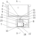
Fig. 1 is a schematic structural view of the present invention;
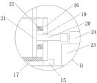
FIG. 2 is an enlarged view of the section B of FIG. 1 according to the present invention;
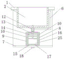
fig. 3 is a cross-sectional view taken along line a-a of fig. 1 according to the present invention.
In the figure: 1. a support frame; 2. a sink body; 3. a water outlet; 4. a sewer pipe; 5. a water cover; 6. an overflow pipe; 7. a base plate; 8. a gear box; 9. a box door; 10. a baffle plate; 11. a mounting frame; 12. a motor; 13. a rotating shaft; 14. a rotary blade; 15. a slider; 16. a recovery box body; 17. a second filter plate; 18. a water outlet pipe; 19. a through hole; 20. a connecting rod; 21. pushing the plate; 22. a spring; 23. a support block; 24. a hydraulic lever; 25. a first filter plate.
Detailed Description
The technical solutions in the embodiments of the present invention will be described clearly and completely with reference to the accompanying drawings in the embodiments of the present invention, and it is obvious that the described embodiments are only some embodiments of the present invention, not all embodiments.
In the description of the present invention, it is to be understood that the terms "upper", "lower", "front", "rear", "left", "right", "top", "bottom", "inner", "outer", and the like indicate orientations or positional relationships based on the orientations or positional relationships shown in the drawings, and are only for convenience of description and simplicity of description, and do not indicate or imply that the device or element being referred to must have a particular orientation, be constructed and operated in a particular orientation, and therefore, should not be construed as limiting the present invention.
Referring to fig. 1-3, a sink with a garbage crushing function comprises a support frame 1, a sink body 2 is fixedly connected to the inner wall of the support frame 1, a water outlet 3 is arranged at the bottom of the sink body 2, a sewer pipe 4 is fixedly communicated with the inner wall of the water outlet 3, an overflow pipe 6 is fixedly communicated with the surface of the sink body 2, the bottom of the overflow pipe 6 is fixedly communicated with the surface of the sewer pipe 4, when the water in the sink body 2 is more, the water flows out of the overflow pipe 6, so that the water cannot overflow to flow to the ground, a water cover 5 is arranged inside the water outlet 3, a bottom plate 7 is fixedly connected to the surface of the support frame 1, a retaining box 8 is fixedly connected to the upper surface of the bottom plate 7, a box door 9 is hinged to the front of the retaining box 8, a recovery box 16 can be taken out by opening the box door 9, so that a user can, the bottom of the downcomer 4 is fixedly connected with the surface of the baffle box 8.
Inner wall fixedly connected with baffle 10 of baffle box 8, and baffle 10 is located downcomer 4's the left and right sides, the bottom fixedly connected with mounting bracket 11 of basin body 2, the left side bolt fixedly connected with motor 12 of mounting bracket 11, shaft coupling fixedly connected with pivot 13 is passed through to the output of motor 12, the fixed surface of pivot 13 is connected with spinning blade 14, and spinning blade 14 is located between the baffle 10 about, downcomer 4's center and pivot 13's center are on same perpendicular, and downcomer 4 is located spinning blade 14's top, make rubbish just in time fall on spinning blade 14, smash rubbish through spinning blade 14.
The upper surface of the bottom plate 7 is fixedly connected with a sliding block 15, the surface of the sliding block 15 and the bottom of the baffle plate 10 are both connected with a recovery box 16 in a sliding manner, the sliding block 15 plays a limiting role on the recovery box 16, the recovery box 16 can not move transversely through the sliding block 15, the recovery box 16 collects kitchen waste, the inner wall of the recovery box 16 is fixedly connected with a second filter plate 17, the waste is separated from water through the second filter plate 17 to prevent the waste from rushing into a sewer, the bottom of the bottom plate 7 is fixedly communicated with a water outlet pipe 18, the right side of the recovery box 16 is provided with a through hole 19, the inner wall of the through hole 19 is connected with a connecting rod 20 in a sliding manner, the left side of the connecting rod 20 is fixedly connected with a push plate 21, the inner wall of the recovery box 16 and the upper surface of the second filter plate 17 are both in contact, the last fixed surface of bottom plate 7 is connected with supporting shoe 23, the last fixed surface of supporting shoe 23 is connected with hydraulic stem 24, the left side of hydraulic stem 24 and the right side contact of connecting rod 20, the opening has been seted up in the left side of retrieving box 16, the first filter 25 of open-ended inner wall fixedly connected with, the bottom of first filter 25 and the upper surface of second filter 17 are at same horizontal plane, the clearance between second filter 17 and the bottom plate 7 is 10 mm.
The utility model discloses in, the user is when using the device, through the water lid 5 of taking, make rubbish flow out from downcomer 4, and simultaneously, it is rotatory to drive pivot 13 through control motor 12, pivot 13 drives spinning blade 14 and makes rubbish smash fast, rubbish after smashing falls to second filter 17, make rubbish and water separate through second filter 17, after rubbish is smashed and is accomplished, remove left through control hydraulic stem 24, the removal of hydraulic stem 24 makes connecting rod 20 remove, connecting rod 20 drives push pedal 21 and promotes rubbish left, through the extrusion of push pedal 21 to rubbish, make the moisture further separation in the rubbish, reduce the volume that rubbish was deposited in retrieving box 16, rubbish moisture separation is accomplished after, hydraulic stem 24 shrink, shrink power pulling connecting rod 20 through spring 22 and push pedal 21 shrink and get back to the initial position.
The above, only be the concrete implementation of the preferred embodiment of the present invention, but the protection scope of the present invention is not limited thereto, and any person skilled in the art is in the technical scope of the present invention, according to the technical solution of the present invention and the utility model, the concept of which is equivalent to replace or change, should be covered within the protection scope of the present invention.
It is noted that, herein, relational terms such as first and second, and the like may be used solely to distinguish one entity or action from another entity or action without necessarily requiring or implying any actual such relationship or order between such entities or actions. Also, the terms "comprises," "comprising," or any other variation thereof, are intended to cover a non-exclusive inclusion, such that a process, method, article, or apparatus that comprises a list of elements does not include only those elements but may include other elements not expressly listed or inherent to such process, method, article, or apparatus.