CN213565404U - New energy automobile battery package and oil tank sharing mounting structure - Google Patents
New energy automobile battery package and oil tank sharing mounting structure Download PDFInfo
- Publication number
- CN213565404U CN213565404U CN202022674744.5U CN202022674744U CN213565404U CN 213565404 U CN213565404 U CN 213565404U CN 202022674744 U CN202022674744 U CN 202022674744U CN 213565404 U CN213565404 U CN 213565404U
- Authority
- CN
- China
- Prior art keywords
- mounting
- oil tank
- cross beam
- new energy
- battery pack
- Prior art date
- Legal status (The legal status is an assumption and is not a legal conclusion. Google has not performed a legal analysis and makes no representation as to the accuracy of the status listed.)
- Active
Links
Images


Abstract
The utility model discloses a new energy automobile battery package and oil tank sharing mounting structure, including front beam, supporting beam group, rear frame member and installing support group, wherein: the front end and the rear end of the supporting beam group are respectively and fixedly connected to the side surfaces of the front cross beam and the rear cross beam, and the mounting bracket group is fixed on the bottom surface of the rear cross beam; the side surface of the front cross beam, the bottom surface of the supporting beam group, the side surface of the rear cross beam and the side surface of the mounting bracket group are continuously encircled to form an accommodating space with an open bottom, and the cross section of the accommodating space is shaped like a Chinese character 'ji'. Compared with the prior art, the utility model can increase the battery pack volume of a pure electric configuration vehicle type as much as possible, and plays a role in increasing the endurance mileage of the vehicle; the battery pack and the oil tank of the hybrid configuration vehicle type can make full use of the bottom space, and the effect of improving the space utilization rate is achieved.
Description
Technical Field
The utility model relates to a car frame technical field, especially a new energy automobile battery package and oil tank sharing mounting structure.
Background
At present, new energy automobiles on the market mainly have two types, one is a pure electric type (only charging is needed), and the other is a fuel-electric hybrid type (charging and refueling can be achieved). For the same new energy automobile with the pure electric configuration and the oil-electricity hybrid configuration, the battery pack of the pure electric configuration is larger than the battery pack of the oil-electricity hybrid configuration, and the automobile type of the oil-electricity hybrid configuration needs to arrange an oil tank besides the battery pack, so that the space utilization rate of the automobile cannot be improved due to the fact that the battery pack of the pure electric configuration is larger than that of the oil-electricity hybrid configuration, or the state of an automobile body metal plate mounting structure can be increased to increase development cost and development period in the design of lower automobile body space arrangement and general mounting points.
SUMMERY OF THE UTILITY MODEL
The utility model aims at providing a new energy automobile battery package and oil tank sharing mounting structure to solve the technical problem among the prior art, it can be in the motorcycle type design that has existing electricelectric configuration and has the hybrid configuration of oil and electricity again, improves the space utilization of automobile body down, makes battery package and oil tank obtain rationalization and arranges, and reduces down automobile body panel beating mounting structure state.
The utility model provides a new energy automobile battery package and oil tank sharing mounting structure, including front beam, supporting beam group, rear frame member and installing support group, wherein:
the front end and the rear end of the supporting beam group are respectively and fixedly connected to the side surfaces of the front cross beam and the rear cross beam, and the mounting bracket group is fixed on the bottom surface of the rear cross beam;
the side surface of the front cross beam, the bottom surface of the supporting beam group, the side surface of the rear cross beam and the side surface of the mounting bracket group are continuously encircled to form an accommodating space with an open bottom, and the cross section of the accommodating space is shaped like a Chinese character 'ji'.
In the above-described mounting structure for a battery pack and an oil tank of a new energy vehicle, preferably, the support beam set includes a plurality of support beams arranged in parallel at intervals.
The new energy automobile battery pack and oil tank sharing mounting structure is characterized in that the mounting bracket set comprises a plurality of mounting brackets arranged in parallel at intervals.
In the above-mentioned new energy automobile battery pack and oil tank shared mounting structure, preferably, the two support beams and the two mounting brackets are arranged one by one in a corresponding manner, and the mounting brackets are located on an axis extension line of the support beams.
As above-mentioned new energy automobile battery package and oil tank sharing mounting structure, wherein, preferably, the installing support includes mounting box and shrouding, wherein:
a hollow cavity is formed in the mounting box, and a first opening is formed in the side face of one side of the mounting box of the hollow cavity;
the outer contoured surface of the closure plate conforms to the inner contoured surface of the first opening to close the first opening.
The new energy automobile battery pack and oil tank shared mounting structure comprises a mounting box, a hollow cavity, a first flange and a rear cross beam, wherein the mounting box is provided with a first opening, the first opening is connected with the end of the second opening, the end of the first opening is connected with the end of the second opening, the hollow cavity is arranged on the bottom surface of the mounting box, the first flange is connected with the rear cross beam, and the rear cross beam is connected with the rear cross beam.
As above, the new energy automobile battery pack and oil tank sharing mounting structure, wherein preferably, the side face of the sealing plate is turned over towards one side of the hollow cavity to form a second flanging, and the second flanging is attached to the side face of the hollow cavity.
As above, the new energy automobile battery pack and oil tank shared mounting structure, wherein preferably, the top surface of the sealing plate faces one side of the hollow cavity and is turned over to form a third flange, the third flange is attached to the top surface of the hollow cavity, the top surface of the hollow cavity is provided with a first mounting hole, the third flange is provided with a second mounting hole, and the axis of the first mounting hole coincides with the axis of the second mounting hole.
In the above common mounting structure for the battery pack and the oil tank of the new energy automobile, preferably, an extension plate is provided on the bottom surface of the sealing plate in a downward protruding manner, and the extension plate is attached to the side surface of the rear cross beam.
The new energy automobile battery pack and oil tank shared mounting structure comprises a front cross beam, a support beam group, a rear cross beam and a mounting bracket group, wherein the front cross beam, the support beam group, the rear cross beam and the mounting bracket group are fixedly connected through spot welding.
Compared with the prior art, the utility model forms an inverted concave structure in a shape like a Chinese character ji through four parts of the front beam, the supporting beam group, the rear beam and the mounting bracket group, so that the volume of the battery pack of a pure electric configuration vehicle type is increased as much as possible, and the effect of increasing the endurance mileage of the vehicle is achieved; the battery pack and the oil tank of the vehicle type with hybrid configuration of oil and electricity can fully utilize the bottom space, and the function of improving the space utilization rate is achieved; meanwhile, the pure electric configuration vehicle type and the oil-electric hybrid configuration vehicle type share one set of metal plate mounting structure, so that the development cost is reduced, and the development period is shortened.
Drawings
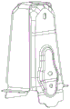
Fig. 1 is a front view of the overall structure of the present invention;
fig. 2 is a bottom view of the overall structure of the present invention;
fig. 3 is an exploded view of the present invention;
FIG. 4 is an isometric view of the mounting bracket;
FIG. 5 is an isometric view of the mounting box;
FIG. 6 is an isometric view of the closure plate;
fig. 7 is a front view of the present invention applied to a pure electric configuration vehicle type state;
fig. 8 is a bottom view of the present invention applied to a state of a pure electric vehicle configuration;
fig. 9 is a front view of the present invention applied to a hybrid configuration vehicle model state;
fig. 10 is a bottom view of the present invention applied to a hybrid vehicle model.
Description of reference numerals: 1-front beam, 2-support beam group, 3-rear beam, 4-mounting bracket group, 5-accommodating space, 6-mounting box, 7-sealing plate, 8-hollow cavity, 9-first opening, 10-second opening, 11-first flanging, 12-second flanging, 13-third flanging, 14-first mounting hole, 15-second mounting hole, 16-extension plate, 17-battery pack and 18-oil tank.
Detailed Description
Reference will now be made in detail to embodiments of the present invention, examples of which are illustrated in the accompanying drawings, wherein like reference numerals refer to the same or similar elements or elements having the same or similar function throughout. The embodiments described below by referring to the drawings are exemplary only for explaining the present invention, and should not be construed as limiting the present invention.
As shown in fig. 1 to 3, the embodiment of the utility model provides a new energy automobile battery package and oil tank sharing mounting structure, including front beam 1, supporting beam group 2, rear beam 3 and installing support group 4, wherein:
both ends fixed connection respectively around the supporting beam group 2 in front beam 1 with on the side of rear beam 3, including a plurality of parallel interval settings's a supporting beam in the supporting beam group 2, in this embodiment, under the prerequisite that reaches the strength requirement, for satisfying the requirement of practicing thrift the cost and reducing weight, establish a supporting beam into two, two supporting beam symmetry sets up, supporting beam's axis direction with front beam 1 with the axis direction looks vertical of rear beam 3.
The mounting bracket group 4 is fixed on the bottom surface of the rear cross beam 3, the mounting bracket group 4 comprises a plurality of mounting brackets which are arranged in parallel at intervals, in the embodiment, on the premise of meeting the requirements of the mounting stability and the strength of the battery pack 17 and the oil tank 18, the requirements of saving cost and reducing weight are further met, so that the number of the two mounting brackets is two, the two mounting brackets are symmetrically arranged, the mounting points of the oil tank 18 and the battery pack 17 are uniformly arranged on the mounting bracket group 4, the mounting bracket group 4 is universal, the number of developed parts is reduced as few as possible, the development cost is reduced, and the development period is also reduced.
In this embodiment, in order to improve the installation stability of whole frame, two the supporting beam with two the installing support corresponds the setting one by one, the installing support is located the axis extension line of supporting beam. Therefore, the fixed gravity center of the whole frame is stable, and higher fixed strength can be kept when the vehicle body swings and jolts, so that deformation and fracture are prevented.
The side surface of the front cross beam 1, the bottom surface of the supporting beam group 2, the side surface of the rear cross beam 3 and the side surface of the mounting bracket group 4 are continuously surrounded to form an accommodating space 5 with an open bottom, the accommodating space 5 is used for accommodating a battery pack 17 or an oil tank 18, and the cross section of the accommodating space 5 is in a shape like a Chinese character 'ji'.
When the pure electric configuration vehicle is installed, referring to fig. 7 and 8: the battery pack 17 can extend backwards, the mounting points are arranged on the two mounting brackets, and in a space shaped like a Chinese character 'ji' formed by the accommodating space 5, the battery pack 17 is locally protruded upwards, so that the space is utilized to the maximum, and the effect of increasing the volume of the battery pack 17 is achieved;
when the hybrid vehicle is installed, referring to fig. 9 and 10: the mounting point of the oil-electricity hybrid configuration battery pack 17 moves forward, the mounting point of the oil tank 18 is arranged on two mounting brackets (the mounting point is the same as the mounting point at the rear part of the pure electric configuration battery pack 17), the space shaped like the Chinese character ji formed by the accommodating space 5 is fully utilized, the oil tank 18 is arranged, the battery pack 17 and the oil tank 18 of the oil-electricity hybrid configuration vehicle type can be reasonably arranged, and the space utilization rate is maximized as far as possible.
Further, as shown in fig. 4-6, the mounting bracket is a split structure, the mounting bracket includes a mounting box 6 and a sealing plate 7, the mounting bracket is formed by spot welding after the mounting box 6 and the sealing plate 7 are fastened, wherein: the mounting box 6 is a box body structure which is gradually contracted in the axial direction, a hollow cavity 8 is formed in the mounting box 6, and a first opening 9 is formed in the side face of one side of the mounting box 6 of the hollow cavity 8; the outer contour surface of the sealing plate 7 is adapted to the inner contour surface of the first opening 9 to seal the first opening 9, so that the purpose of light weight is achieved, and meanwhile, the metal plate manufacturing is easy.
Furthermore, the hollow cavity 8 forms a second opening 10 on the bottom surface of the mounting box 6, the end portions of the first opening 9 and the second opening 10 are connected to form an L-shaped structure, the bottom surface of the mounting box 6 is turned outwards to form a first turned edge 11, and the first turned edge 11 is attached to the bottom surface of the rear cross beam 3, so that the welding strength of the mounting box 6 and the rear cross beam 3 is improved.
Further, in order to improve the buckling welding strength of the sealing plate 7 and the mounting box 6, the side face of the sealing plate 7 is turned towards one side of the hollow cavity 8 to form a second flanging 12, and the second flanging 12 is attached to the side face of the hollow cavity 8.
Further, the top surface of the sealing plate 7 is turned over towards one side of the hollow cavity 8 to form a third turned edge 13, the third turned edge 13 is attached to the top surface of the hollow cavity 8, a first mounting hole 14 is formed in the top surface of the hollow cavity 8, a second mounting hole 15 is formed in the third turned edge 13, and the axis of the first mounting hole 14 coincides with the axis of the second mounting hole 15. The mounting points of the oil tank 18 and the battery pack 17 are arranged at the first mounting hole 14 and the second mounting hole 15, so that the mounting structures of the battery pack 17 and the oil tank 18 which are not only in pure electric configuration but also in hybrid configuration of vehicles can be universal, the development cost of parts is reduced, and the project development period is shortened.
Further, in order to improve the welding fixing strength of the sealing plate 7 and the rear cross beam 3, an extension plate 16 is arranged on the bottom surface of the sealing plate 7 in a downward protruding mode, and the extension plate 16 is attached to the side surface of the rear cross beam 3.
Further, the front cross beam 1, the supporting beam group 2, the rear cross beam 3 and the mounting bracket group 4 are fixedly connected through spot welding. The integral installation steps comprise that firstly, a single piece of the front cross beam 1 is designed, and a piece is formed by punching a sheet metal; secondly, designing a single piece of the supporting beam group 2, punching and forming a metal plate, wherein the number of the single piece is two, and the two pieces are universal; designing a single piece of the rear cross beam 3, and punching and forming a metal plate; designing a mounting bracket group 3, wherein the mounting bracket is formed by buckling and then spot-welding two mounting boxes 6 and two sealing plates 7, and the number of the mounting brackets used for the bicycle is two; and finally, spot welding the front cross beam 1, the support beam group 2, the rear cross beam 3 and the mounting bracket group 4 to form the whole frame rear section cross beam structure.
In the embodiment, the front cross beam 1, the support beam group 2, the rear cross beam 3 and the mounting bracket group 4 form the inverted concave structure in a shape like a Chinese character ji, so that the volume of the battery pack 17 of a pure electric configuration vehicle type is increased as much as possible, and the effect of increasing the endurance mileage of the vehicle is achieved; the battery pack 17 and the oil tank 18 of the vehicle type with hybrid configuration of oil and electricity can fully utilize the bottom space, and the function of improving the space utilization rate is achieved; meanwhile, the pure electric configuration vehicle type and the oil-electric hybrid configuration vehicle type share one set of metal plate mounting structure, so that the development cost is reduced, and the development period is shortened.
The structure, features and effects of the present invention have been described in detail above according to the embodiment shown in the drawings, and the above description is only the preferred embodiment of the present invention, but the present invention is not limited to the implementation scope shown in the drawings, and all changes made according to the idea of the present invention or equivalent embodiments modified to the same changes should be considered within the protection scope of the present invention when not exceeding the spirit covered by the description and drawings.
Claims (10)
1. The utility model provides a new energy automobile battery package and oil tank sharing mounting structure which characterized in that, includes front beam, supporting beam group, rear beam and installing support group, wherein:
the front end and the rear end of the supporting beam group are respectively and fixedly connected to the side surfaces of the front cross beam and the rear cross beam, and the mounting bracket group is fixed on the bottom surface of the rear cross beam;
the side surface of the front cross beam, the bottom surface of the supporting beam group, the side surface of the rear cross beam and the side surface of the mounting bracket group are continuously encircled to form an accommodating space with an open bottom, and the cross section of the accommodating space is shaped like a Chinese character 'ji'.
2. The new energy automobile battery pack and oil tank common mounting structure as claimed in claim 1, wherein the support beam set comprises a plurality of support beams arranged in parallel at intervals.
3. The new energy automobile battery pack and oil tank common mounting structure as claimed in claim 2, wherein the mounting bracket set comprises a plurality of parallel mounting brackets arranged at intervals.
4. The new energy automobile battery pack and oil tank common mounting structure according to claim 3, wherein the two support beams and the two mounting brackets are arranged one by one, and the mounting brackets are located on an axis extension line of the support beams.
5. The new energy automobile battery pack and oil tank common mounting structure of claim 1, wherein the mounting bracket comprises a mounting box and a sealing plate, wherein:
a hollow cavity is formed in the mounting box, and a first opening is formed in the side face of one side of the mounting box of the hollow cavity;
the outer contoured surface of the closure plate conforms to the inner contoured surface of the first opening to close the first opening.
6. The new energy automobile battery pack and oil tank shared mounting structure as claimed in claim 5, wherein the hollow cavity forms a second opening on the bottom surface of the mounting box, ends of the first opening and the second opening are connected to form an L-shaped structure, the bottom surface of the mounting box is turned outwards to form a first flange, and the first flange is attached to the bottom surface of the rear cross beam.
7. The new energy automobile battery pack and oil tank common mounting structure as claimed in claim 5, wherein a side face of the sealing plate is folded towards one side of the hollow cavity to form a second flange, and the second flange is attached to the side face of the hollow cavity.
8. The new energy automobile battery pack and oil tank shared mounting structure as claimed in claim 5, wherein a top surface of the sealing plate is folded towards one side of the hollow cavity to form a third flange, the third flange is attached to the top surface of the hollow cavity, a first mounting hole is formed in the top surface of the hollow cavity, a second mounting hole is formed in the third flange, and an axis of the first mounting hole coincides with an axis of the second mounting hole.
9. The new energy automobile battery pack and fuel tank common mounting structure of claim 5, wherein an extension plate is convexly arranged on the bottom surface of the sealing plate downwards, and the extension plate is attached to the side surface of the rear cross beam.
10. The new energy automobile battery pack and oil tank common mounting structure according to any one of claims 1 to 9, wherein the front cross beam, the support beam set, the rear cross beam and the mounting bracket set are fixedly connected by spot welding.
Priority Applications (1)
| Application Number | Priority Date | Filing Date | Title |
|---|---|---|---|
| CN202022674744.5U CN213565404U (en) | 2020-11-18 | 2020-11-18 | New energy automobile battery package and oil tank sharing mounting structure |
Applications Claiming Priority (1)
| Application Number | Priority Date | Filing Date | Title |
|---|---|---|---|
| CN202022674744.5U CN213565404U (en) | 2020-11-18 | 2020-11-18 | New energy automobile battery package and oil tank sharing mounting structure |
Publications (1)
| Publication Number | Publication Date |
|---|---|
| CN213565404U true CN213565404U (en) | 2021-06-29 |
Family
ID=76538715
Family Applications (1)
| Application Number | Title | Priority Date | Filing Date |
|---|---|---|---|
| CN202022674744.5U Active CN213565404U (en) | 2020-11-18 | 2020-11-18 | New energy automobile battery package and oil tank sharing mounting structure |
Country Status (1)
| Country | Link |
|---|---|
| CN (1) | CN213565404U (en) |
Cited By (2)
| Publication number | Priority date | Publication date | Assignee | Title |
|---|---|---|---|---|
| CN114013269A (en) * | 2021-11-13 | 2022-02-08 | 安徽江淮汽车集团股份有限公司 | Oil tank mounting bracket |
| CN114734804A (en) * | 2022-03-17 | 2022-07-12 | 盐城市步高汽配制造有限公司 | Battery integrated chassis for new energy vehicle |
-
2020
- 2020-11-18 CN CN202022674744.5U patent/CN213565404U/en active Active
Cited By (4)
| Publication number | Priority date | Publication date | Assignee | Title |
|---|---|---|---|---|
| CN114013269A (en) * | 2021-11-13 | 2022-02-08 | 安徽江淮汽车集团股份有限公司 | Oil tank mounting bracket |
| CN114013269B (en) * | 2021-11-13 | 2024-03-08 | 安徽江淮汽车集团股份有限公司 | Oil tank installing support |
| CN114734804A (en) * | 2022-03-17 | 2022-07-12 | 盐城市步高汽配制造有限公司 | Battery integrated chassis for new energy vehicle |
| CN114734804B (en) * | 2022-03-17 | 2024-01-12 | 盐城市步高汽配制造有限公司 | Battery integrated chassis for new energy vehicle |
Similar Documents
| Publication | Publication Date | Title |
|---|---|---|
| CN213565404U (en) | New energy automobile battery package and oil tank sharing mounting structure | |
| CN113602364B (en) | Threshold longeron, electric automobile body frame and electric automobile | |
| CN205010322U (en) | Installing support subassembly on car front longitudinal | |
| CN112606912B (en) | Rear longitudinal beam assembly and vehicle | |
| CN211195824U (en) | Connection supporting structure of automobile power battery | |
| CN216450735U (en) | Power battery switching support of new energy automobile | |
| CN213199905U (en) | Front wheel cover assembly | |
| CN213413974U (en) | Rear floor front beam structure for new energy automobile | |
| CN210970717U (en) | Mounting structure of hybrid electric vehicle expansion tank and charging socket | |
| CN210628374U (en) | Power battery package box structure | |
| CN211592275U (en) | Hydrogen-electricity hybrid vehicle charger mounting structure | |
| CN220358239U (en) | Lower box structure of battery pack | |
| CN112061246A (en) | Vehicle body rear floor structure for hybrid vehicle | |
| CN212267648U (en) | Front cross beam of rear floor of electric automobile | |
| CN213768240U (en) | Mounting structure of range-extending type electric vehicle storage battery | |
| CN211223004U (en) | Bearing frame of electric automobile power assembly | |
| CN210264287U (en) | Automobile engine apron hinge mount board | |
| CN220842772U (en) | Seat barrel structure and electric bicycle with same | |
| CN217917589U (en) | Battery package installing support and car | |
| CN217574926U (en) | Quick change support and electric automobile are used to battery package | |
| CN218519743U (en) | Steering gear arrangement structure and have new energy automobile of this structure | |
| CN218805054U (en) | Vehicle provided with platformization air pump | |
| CN220199037U (en) | Integrated form electricity drives system assembly and bears structure | |
| CN212625918U (en) | Shell assembly of battery pack and battery pack with same | |
| CN216916033U (en) | Automobile body force transmission structure and vehicle |
Legal Events
| Date | Code | Title | Description |
|---|---|---|---|
| GR01 | Patent grant | ||
| GR01 | Patent grant |