CN213522569U - Press fitting device is used in processing of accurate printed wiring board - Google Patents
Press fitting device is used in processing of accurate printed wiring board Download PDFInfo
- Publication number
- CN213522569U CN213522569U CN202022275873.7U CN202022275873U CN213522569U CN 213522569 U CN213522569 U CN 213522569U CN 202022275873 U CN202022275873 U CN 202022275873U CN 213522569 U CN213522569 U CN 213522569U
- Authority
- CN
- China
- Prior art keywords
- fixedly connected
- groove
- mounting
- grooves
- block
- Prior art date
- Legal status (The legal status is an assumption and is not a legal conclusion. Google has not performed a legal analysis and makes no representation as to the accuracy of the status listed.)
- Active
Links
Images


Landscapes
- Presses And Accessory Devices Thereof (AREA)
Abstract
The utility model discloses a compression fittings is used in processing of accurate printed wiring board, including drive case, landing leg, chamber door, frame, bearing platen, pneumatic cylinder and pressfitting platen subassembly, the equal fixedly connected with landing leg in four corners department of drive bottom of the case portion, the front side of drive case is provided with the chamber door, the top fixedly connected with frame of drive case, the mid point fixedly connected with bearing platen at drive top of the case portion, the equal fixedly connected with pneumatic cylinder in the left and right sides at frame top, the bottom of pneumatic cylinder runs through the frame and extends to its inside, the bottom of pneumatic cylinder is provided with pressfitting platen subassembly. The utility model discloses a drive case, landing leg, chamber door, frame, bearing platen, pneumatic cylinder and pressfitting platen subassembly mutually support, have played the effect of conveniently changing the pressfitting platen, and operation process is very simple and convenient, and need not with the help of any instrument, has brought very big facility for the user, has effectively improved the work efficiency of this device.
Description
Technical Field
The utility model relates to a compression fittings technical field specifically is a compression fittings is used in processing of accurate printed wiring board.
Background
Like application number CN 201820767499.2's patent, a compression fittings is used in processing of accurate printed wiring board, including the drive case with control the platform, the front end surface of drive case is equipped with the dodge gate, and the lower extreme internal surface of drive case has the regulation foot screw near the equal movable mounting in position department of both sides, the upper end external fixed surface of drive case installs the bearing platen, and the equal movable mounting in position department that the upper end internal surface of bearing platen is close to both sides has the sleeve that resets, telescopic inside movable mounting that resets has reset spring, the upper end surface of drive case is located the equal fixed mounting in both ends surface of bearing platen has the support frame, and one side internal fixed surface of support frame installs the sliding tray. A compression fittings is used in processing of accurate printed wiring board, be equipped with sleeve and the direction slider that resets, can conveniently take off the material after the pressfitting is accomplished to can improve equipment's result of use, be suitable for different working conditions, bring better use prospect. However, the above patent has the problem that the press-fit bedplate is inconvenient to replace, thereby causing great inconvenience to users and influencing the working efficiency of the device.
SUMMERY OF THE UTILITY MODEL
An object of the utility model is to provide a compression fittings is used in processing of accurate printed wiring board to solve the problem that proposes among the above-mentioned background art.
In order to achieve the above object, the utility model provides a following technical scheme: a pressing device for machining a precise printed circuit board comprises a driving box, supporting legs, a box door, a rack, a bearing bedplate, a hydraulic cylinder and a pressing bedplate component, wherein the supporting legs are fixedly connected to four corners of the bottom of the driving box, the box door is arranged on the front side of the driving box, the rack is fixedly connected to the top of the driving box, the bearing bedplate is fixedly connected to the middle point of the top of the driving box, the hydraulic cylinder is fixedly connected to the left side and the right side of the top of the rack, the bottom of the hydraulic cylinder penetrates through the rack and extends into the rack, and the pressing bedplate component is arranged at the bottom of the hydraulic cylinder;
the pressing bedplate component comprises mounting plates, mounting grooves, a pressing bedplate, inserting blocks, limiting grooves, fixing plates, through grooves, limiting blocks, movable grooves, telescopic rods, supporting plates, supporting springs, fixing blocks, clamping grooves and clamping blocks, the bottom of the hydraulic cylinder is fixedly connected with the mounting plates, the bottom of each mounting plate is symmetrically provided with two mounting grooves, the bottom of each mounting plate is movably connected with the pressing bedplate, the positions of the tops of the pressing bedplate corresponding to the mounting grooves are fixedly connected with the inserting blocks, the tops of the inserting blocks penetrate through the mounting grooves and extend into the mounting grooves, the sides, far away from each other, of the two inserting blocks are respectively provided with the limiting grooves, the positions, corresponding to the limiting grooves, of the left side and the right side of each mounting plate are respectively provided with the through grooves, the through grooves are mutually communicated with the mounting grooves, and the limiting blocks are fixedly, the limiting block is kept away from one side of fixed plate and is run through logical groove and spacing groove in proper order and extend to the inside of spacing groove, the activity groove has been seted up at the top of fixed plate, two telescopic links of bottom fixedly connected with of activity inslot wall, backup pad fixed connection is passed through at the top of two telescopic links, supporting spring has been cup jointed on the surface of telescopic link, the equal fixedly connected with fixed block in top of the mounting panel left and right sides, the draw-in groove has been seted up to the bottom of fixed block, the position fixedly connected with fixture block of the corresponding draw-in groove in backup pad top, the inside that activity groove and draw-in groove just extended to the draw-in groove is.
Preferably, the bottom of the supporting leg is fixedly connected with a shock pad, and the shock pad is made of rubber.
Preferably, the inserting block is inserted into the mounting groove, and the size of the inserting block is matched with that of the mounting groove.
Preferably, the limiting block is inserted into the limiting groove, and the limiting block is connected with the through groove in a sliding mode.
Preferably, one side of the supporting plate, which is far away from the mounting plate, penetrates through the movable groove and extends to the outside of the movable groove, and the supporting plate is movably connected with the movable groove.
Preferably, the top of the supporting spring is fixedly connected with the bottom of the supporting plate, and the bottom of the supporting spring is fixedly connected with the bottom of the inner wall of the movable groove.
Compared with the prior art, the beneficial effects of the utility model are as follows:
the utility model discloses a drive case, landing leg, chamber door, frame, bearing platen, pneumatic cylinder and pressfitting platen subassembly mutually support, have played the effect of conveniently changing the pressfitting platen, and operation process is very simple and convenient, and need not with the help of any instrument, has brought very big facility for the user, has effectively improved the work efficiency of this device.
Drawings
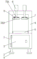
FIG. 1 is a structural section view in elevation of the present invention;
FIG. 2 is an enlarged schematic view of A of FIG. 1 according to the present invention;
fig. 3 is an enlarged schematic view of B in fig. 2 according to the present invention.
In the figure: the device comprises a driving box 1, a supporting leg 2, a box door 3, a rack 4, a bearing bedplate 5, a hydraulic cylinder 6, a pressing bedplate component 7, a mounting plate 701, a mounting groove 702, a pressing bedplate 703, an insertion block 704, a limiting groove 705, a fixing plate 706, a through groove 707, a limiting block 708, a movable groove 709, a telescopic rod 710, a supporting plate 711, a supporting spring 712, a fixing block 713, a clamping groove 714, a clamping block 715 and a shock pad 8.
Detailed Description
The technical solutions in the embodiments of the present invention will be described clearly and completely with reference to the accompanying drawings in the embodiments of the present invention, and it is obvious that the described embodiments are only some embodiments of the present invention, not all embodiments. Based on the embodiments in the present invention, all other embodiments obtained by a person skilled in the art without creative work belong to the protection scope of the present invention.
Referring to fig. 1-3, a pressing device for processing a precision printed circuit board comprises a driving box 1, supporting legs 2, a box door 3, a frame 4, a bearing bedplate 5, a hydraulic cylinder 6 and a pressing bedplate component 7, wherein the supporting legs 2 are fixedly connected to four corners of the bottom of the driving box 1, the box door 3 is arranged on the front side of the driving box 1, the frame 4 is fixedly connected to the top of the driving box 1, the bearing bedplate 5 is fixedly connected to the middle point of the top of the driving box 1, the hydraulic cylinders 6 are fixedly connected to the left side and the right side of the top of the frame 4, the bottom of the hydraulic cylinder 6 penetrates through the frame 4 and extends into the frame, the pressing bedplate component 7 is arranged at the bottom of the hydraulic cylinder 6, a shock pad 8 is fixedly connected to the bottom.
The pressing bedplate component 7 comprises a mounting plate 701, mounting grooves 702, a pressing bedplate 703, inserting blocks 704, limiting grooves 705, a fixing plate 706, a through groove 707, a limiting block 708, a movable groove 709, an expansion rod 710, a support plate 711, a support spring 712, a fixing block 713, a clamping groove 714 and a clamping block 715, the bottom of the hydraulic cylinder 6 is fixedly connected with the mounting plate 701, the bottom of the mounting plate 701 is symmetrically provided with two mounting grooves 702, the bottom of the mounting plate 701 is movably connected with the pressing bedplate 703, the top of the pressing bedplate 703 is fixedly connected with the inserting block 704 corresponding to the position of the mounting groove 702, the top of the inserting block 704 penetrates through the mounting groove 702 and extends into the mounting groove 702, the inserting block 704 is inserted into the mounting groove 702, the size of the inserting block 704 is matched with the mounting groove 702, one side of the two inserting blocks 704, which is far away from each, the left side and the right side of the mounting plate 701 and the position corresponding to the limiting groove 705 are both provided with a through groove 707, the through groove 707 is communicated with the mounting groove 702, the middle point of one side of the fixing plate 706 close to the mounting plate 701 is fixedly connected with a limiting block 708, the limiting block 708 is inserted into the limiting groove 705, the limiting block 708 is connected with the through groove 707 in a sliding way, one side of the limiting block 708 far away from the fixing plate 706 sequentially penetrates through the through groove 707 and the limiting groove 705 and extends to the inside of the limiting groove 705, the top of the fixing plate 706 is provided with a movable groove 709, the bottom of the inner wall of the movable groove 709 is fixedly connected with two telescopic rods 710, the tops of the two telescopic rods 710 are fixedly connected through a support plate 711, one side of the support plate 711 far away from the mounting plate 701 penetrates through the movable groove 709 and extends to the outside thereof, the support, the bottom of the supporting spring 712 is fixedly connected with the bottom of the inner wall of the movable groove 709, the tops of the left side and the right side of the mounting plate 701 are fixedly connected with fixing blocks 713, the bottom of the fixing blocks 713 is provided with clamping grooves 714, the top of the supporting plate 711 corresponds to the clamping grooves 714 and is fixedly connected with clamping blocks 715, the tops of the clamping blocks 715 sequentially penetrate through the movable groove 709 and the clamping grooves 714 and extend to the clamping grooves 714, and the clamping blocks 715 are inserted into the clamping grooves 714.
When the pressing bedplate 703 needs to be replaced, the supporting plate 711 is pulled downwards to drive the blocking block 715 to move downwards, the telescopic rod 710 and the supporting spring 712 are compressed, the blocking block 715 is separated from the clamping groove 714, the fixing plate 706 is pulled towards one side away from the limiting groove 705, the limiting block 708 is driven to move towards one side away from the limiting groove 705, the limiting block 708 is separated from the limiting groove 705, the inserting block 704 is taken out of the mounting groove 702, the pressing bedplate 703 can be taken down, a new pressing bedplate 703 can be placed at the bottom of the mounting plate 701, the inserting block 704 is inserted into the corresponding mounting groove 702, the supporting plate 711 is pressed downwards, the blocking block 715 is lowered to the position below the fixing block 713, the fixing plate 706 is pushed towards one side close to the mounting plate 701, and the limiting block 708 is inserted into the limiting groove 705, then, the supporting plate 711 is loosened, so that the supporting plate 711 and the locking block 715 are driven to reset under the elastic force of the supporting spring 712, and the locking block 715 is inserted into the locking slot 714.
Although embodiments of the present invention have been shown and described, it will be appreciated by those skilled in the art that changes, modifications, substitutions and alterations can be made in these embodiments without departing from the principles and spirit of the invention, the scope of which is defined in the appended claims and their equivalents.
Claims (6)
1. The utility model provides a compression fittings is used in processing of accurate printed wiring board, includes drive case (1), landing leg (2), chamber door (3), frame (4), bearing platen (5), pneumatic cylinder (6) and pressfitting platen subassembly (7), its characterized in that: the four corners of the bottom of the driving box (1) are fixedly connected with supporting legs (2), a box door (3) is arranged on the front side of the driving box (1), the top of the driving box (1) is fixedly connected with a rack (4), a bearing bedplate (5) is fixedly connected with the midpoint of the top of the driving box (1), hydraulic cylinders (6) are fixedly connected to the left side and the right side of the top of the rack (4), the bottoms of the hydraulic cylinders (6) penetrate through the rack (4) and extend into the rack, and press-fit bedplate components (7) are arranged at the bottoms of the hydraulic cylinders (6);
the pressing bedplate component (7) comprises a mounting plate (701), mounting grooves (702), a pressing bedplate (703), insert blocks (704), a limiting groove (705), a fixing plate (706), a through groove (707), a limiting block (708), a movable groove (709), a telescopic rod (710), a support plate (711), a support spring (712), a fixing block (713), a clamping groove (714) and a clamping block (715), wherein the bottom of the hydraulic cylinder (6) is fixedly connected with the mounting plate (701), the bottom of the mounting plate (701) is symmetrically provided with two mounting grooves (702), the bottom of the mounting plate (701) is movably connected with the pressing bedplate (703), the top of the pressing bedplate (703) is fixedly connected with the insert blocks (704) corresponding to the mounting grooves (702), the top of the insert blocks (704) penetrates through the mounting grooves (702) and extends into the mounting grooves, one side of the two insert blocks (704) far away from each other is, the mounting plate comprises a mounting plate (701), fixing plates (706) are movably connected to the left side and the right side of the mounting plate (701) and the positions corresponding to limiting grooves (705), through grooves (707) are formed in the left side and the right side of the mounting plate (701) and the positions corresponding to the limiting grooves (705), the through grooves (707) are communicated with the mounting groove (702), a limiting block (708) is fixedly connected to the middle point of one side, close to the mounting plate (701), of the fixing plate (706), one side, far away from the fixing plate (706), of the limiting block (708 sequentially penetrates through the through grooves (707) and the limiting grooves (705) and extends into the limiting grooves (705), a movable groove (709) is formed in the top of the fixing plate (706), two telescopic rods (710) are fixedly connected to the bottom of the inner wall of the movable groove (709), the tops of the two telescopic rods (710) are fixedly connected through supporting plates, the top of the left side and the right side of the mounting plate (701) is fixedly connected with a fixing block (713), the bottom of the fixing block (713) is provided with a clamping groove (714), the top of the supporting plate (711) corresponds to a clamping groove (714) and is fixedly connected with a clamping block (715), the top of the clamping block (715) sequentially penetrates through the movable groove (709) and the clamping groove (714) and extends to the inside of the clamping groove (714), and the clamping block (715) is connected with the clamping groove (714) in an inserting mode.
2. The pressing device for processing the precise printed circuit board according to claim 1, wherein: the bottom of landing leg (2) fixedly connected with shock pad (8), shock pad (8) are made by rubber.
3. The pressing device for processing the precise printed circuit board as claimed in claim 2, wherein: the plug block (704) is plugged with the mounting groove (702), and the size of the plug block (704) is matched with that of the mounting groove (702).
4. The pressing device for processing the precise printed circuit board as claimed in claim 3, wherein: the limiting block (708) is inserted into the limiting groove (705), and the limiting block (708) is connected with the through groove (707) in a sliding mode.
5. The pressing device for processing the precise printed circuit board as claimed in claim 4, wherein: one side of the supporting plate (711) far away from the mounting plate (701) penetrates through the movable groove (709) and extends to the outside of the movable groove, and the supporting plate (711) is movably connected with the movable groove (709).
6. The pressing device for processing the precise printed circuit board as claimed in claim 5, wherein: the top of the supporting spring (712) is fixedly connected with the bottom of the supporting plate (711), and the bottom of the supporting spring (712) is fixedly connected with the bottom of the inner wall of the movable groove (709).
Priority Applications (1)
| Application Number | Priority Date | Filing Date | Title |
|---|---|---|---|
| CN202022275873.7U CN213522569U (en) | 2020-10-14 | 2020-10-14 | Press fitting device is used in processing of accurate printed wiring board |
Applications Claiming Priority (1)
| Application Number | Priority Date | Filing Date | Title |
|---|---|---|---|
| CN202022275873.7U CN213522569U (en) | 2020-10-14 | 2020-10-14 | Press fitting device is used in processing of accurate printed wiring board |
Publications (1)
| Publication Number | Publication Date |
|---|---|
| CN213522569U true CN213522569U (en) | 2021-06-22 |
Family
ID=76397097
Family Applications (1)
| Application Number | Title | Priority Date | Filing Date |
|---|---|---|---|
| CN202022275873.7U Active CN213522569U (en) | 2020-10-14 | 2020-10-14 | Press fitting device is used in processing of accurate printed wiring board |
Country Status (1)
| Country | Link |
|---|---|
| CN (1) | CN213522569U (en) |
-
2020
- 2020-10-14 CN CN202022275873.7U patent/CN213522569U/en active Active
Similar Documents
| Publication | Publication Date | Title |
|---|---|---|
| CN211505053U (en) | Measuring device for automobile inspection engineering | |
| CN210444657U (en) | Electrical connector abnormal heating test electrical cabinet | |
| CN213522569U (en) | Press fitting device is used in processing of accurate printed wiring board | |
| CN208827429U (en) | A kind of copper sheet engraving is with from dynamic pressure fixture | |
| CN113777890B (en) | Telescopic pressing plate mechanism, exposure machine with same and pressing plate method of exposure machine | |
| CN209664747U (en) | A kind of pressing tool of router | |
| CN217224541U (en) | Fixing device for maintaining tool clamp | |
| CN114336361B (en) | Modular assembly type low-voltage switch cabinet and assembly method | |
| CN215340123U (en) | Fixing clamp for testing electronic product | |
| CN211968866U (en) | Printing plate fixing device | |
| CN217835092U (en) | Stop device for gilt version | |
| CN220009299U (en) | Embossing machine convenient to change embossing pattern | |
| CN106425974B (en) | A kind of electric parking brake shell assembly method | |
| CN219426696U (en) | Workpiece positioning and press-fitting device | |
| CN220661232U (en) | Device for pressing edges of thick table plates | |
| CN110899853A (en) | Sculpture device is used in machine parts production | |
| CN216330314U (en) | Auto-parts press that machining precision is high | |
| CN215792490U (en) | Slidingtype duplex position pneumatic pyrograph machine | |
| CN218852084U (en) | Sole printing equipment | |
| CN214960642U (en) | Flexible line way board location frock | |
| CN215879544U (en) | But automatic feeding formula punching machine | |
| CN212230287U (en) | Clamp for capacitor core shaping | |
| CN221024993U (en) | Storage box for ground resistance tester | |
| CN216264052U (en) | Device for engraving surface of crystal glass | |
| CN216624474U (en) | External battery suitable for mobile device |
Legal Events
| Date | Code | Title | Description |
|---|---|---|---|
| GR01 | Patent grant | ||
| GR01 | Patent grant |