CN213513049U - Positioning device for computer host - Google Patents
Positioning device for computer host Download PDFInfo
- Publication number
- CN213513049U CN213513049U CN202020638488.1U CN202020638488U CN213513049U CN 213513049 U CN213513049 U CN 213513049U CN 202020638488 U CN202020638488 U CN 202020638488U CN 213513049 U CN213513049 U CN 213513049U
- Authority
- CN
- China
- Prior art keywords
- rod
- movable
- placing plate
- driving
- positioning device
- Prior art date
- Legal status (The legal status is an assumption and is not a legal conclusion. Google has not performed a legal analysis and makes no representation as to the accuracy of the status listed.)
- Expired - Fee Related
Links
Images


Landscapes
- Transmission Devices (AREA)
Abstract
The utility model discloses a positioning device for a computer mainframe, which belongs to the technical field of computer mainframes, and comprises a placing plate, wherein thread-mounted vertically-arranged thread columns are arranged at two ends of the placing plate, the bottom of the thread column is rotationally connected with a connecting rod, one end of the connecting rod is provided with a first clamping plate, two second clamping plates are slidably mounted at the top of the placing plate, a driving groove is formed at the top of the placing plate, two movable blocks which are symmetrically arranged relative to the vertical center of the driving groove are slidably mounted in the driving groove, the top of each movable block is fixedly connected with the bottom of the second clamping plate, a driving rod is rotatably mounted in the driving groove, and the driving rod is in threaded connection with the movable blocks; the utility model discloses the realization is to the transverse orientation and the longitudinal positioning of computer mainframe for stable the placing on the desk of host computer improves the security, and the convenience combines or dismantles device and desk simultaneously.
Description
Technical Field
The utility model belongs to the technical field of the main frame, concretely relates to a positioner for main frame.
Background
The computer host refers to the main body part of the computer except the input and output equipment. And is also a control box body for placing the main board and other main components. Typically including a CPU, memory, hard disk, optical drive, power supply, and other input/output controllers and interfaces. When the existing computer host is placed on a desk, no fixing measures are provided, and the computer host is easily damaged due to accidental rubbing and falling, so that a positioning device for the computer host is needed to solve the problems.
SUMMERY OF THE UTILITY MODEL
An object of the utility model is to provide a positioner for computer host computer to solve the problem that proposes among the above-mentioned background art.
In order to achieve the above object, the utility model provides a following technical scheme: a positioning device for a computer host comprises a placing plate, wherein two ends of the placing plate are provided with vertically arranged threaded columns in a threaded manner, the bottom of each threaded column is rotatably connected with a connecting rod, one end of the connecting rod is provided with a first clamping plate, the top of the placing plate is provided with two second clamping plates in a sliding manner, the top of the placing plate is provided with a driving groove, two movable blocks which are symmetrically arranged relative to the vertical center plane of the driving groove are arranged in the driving groove in a sliding manner, the top of each movable block is fixedly connected with the bottom of the corresponding second clamping plate, a driving rod is rotatably arranged in the driving groove and is in threaded connection with the movable blocks, the placing plate is provided with a cavity, a horizontally arranged transverse shaft is rotatably arranged in the cavity, one end of the transverse shaft is in transmission connection with the driving rod, two ends of the top of the second clamping plate are provided with first positioning blocks, and one side of the two first positioning blocks, the second locating piece is installed to the relative one end of two movable rods, the other end of movable rod runs through first locating piece and installs the handle, be equipped with the compression chamber on the first locating piece, slidable mounting has the slide in the compression chamber, and the cover is equipped with the spring on the movable rod, and the spring is located one side that the second locating piece was kept away from to the slide.
As a preferred embodiment, the actuating lever comprises a left threaded rod and a right threaded rod, the thread directions of the left threaded rod and the right threaded rod are opposite, and the two movable blocks are respectively in threaded connection with the left threaded rod and the right threaded rod.
As a preferred embodiment, a gear is fixedly sleeved on the transverse shaft, a rack is slidably mounted on the inner wall of the bottom of the cavity, the rack is meshed with the gear, an electric telescopic rod is arranged in the cavity, and a piston rod of the electric telescopic rod is in transmission connection with the rack.
As a preferred embodiment, a movable block is slidably mounted in the cavity, and the movable block is fixedly connected with one end of the rack far away from the electric telescopic rod.
As a preferred embodiment, a backing plate is arranged on one side of each of the two second clamping plates, the backing plate is made of polyurethane, and the vertical section of each of the second clamping plates is of an L-shaped structure.
As a preferred embodiment, the connecting rod is of a J-shaped structure, a groove is formed in the top of the connecting rod, a bearing is installed in the groove, and the bottom of the threaded column is fixedly connected with an inner ring of the bearing.
Compared with the prior art, the beneficial effects of the utility model are that:
on placing the board and placing the desk, rotate and rotate the screw thread post and make the screw thread post rise and drive the connecting rod and rise, handheld connecting rod does not take place to rotate and only carries out elevating movement for the connecting rod drives first grip block and rises, and first grip block supports and presses in the bottom of desktop, realizes the fixed to placing the board, makes to place the board and installs on the desktop, easy to assemble and dismantlement.
Place the host computer on placing the board, then drive the rack through electric telescopic handle and remove and make gear revolve drive the cross axle and rotate for the actuating lever rotates and drives left threaded rod and right threaded rod and rotates and make two movable blocks be close to each other and drive the both sides that two second grip blocks moved in opposite directions and grasp the host computer, realizes the transverse orientation to the host computer, improves the security.
Through pulling the handle when two second grip blocks centre gripping get and make the movable rod to keeping away from the one side motion of second locating piece for the host computer position is located between two second locating pieces, then loosen the handle, promote the slide under the effect of the restoring force of spring and drive the other both sides of movable rod and slide centre gripping host computer to the motion of second locating piece, realize the vertical location to the host computer, improve the security.
The utility model discloses the realization is to the transverse orientation and the longitudinal positioning of computer mainframe for stable the placing on the desk of host computer improves the security, and the convenience combines or dismantles device and desk simultaneously.
Drawings
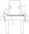
Fig. 1 is a schematic structural view of the present invention;
fig. 2 is a schematic top view of the positioning block of the present invention;
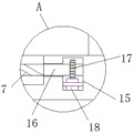
FIG. 3 is a schematic view of the structure at A in FIG. 1;
fig. 4 is a schematic view of the cavity overlooking structure of the present invention.
In the figure: 1. placing the plate; 2. a threaded post; 3. a connecting rod; 4. a first clamping plate; 5. a second clamping plate; 6. a drive slot; 7. a drive rod; 8. a movable block; 9. a first positioning block; 10. A compression chamber; 11. a movable rod; 12. a second positioning block; 13. a slide plate; 14. a spring; 15. a cavity; 16. a horizontal axis; 17. a gear; 18. a rack; 19. an electric telescopic rod.
Detailed Description
The present invention will be further described with reference to the following examples.
The following examples are intended to illustrate the invention, but are not intended to limit the scope of the invention. The condition in the embodiment can be further adjusted according to concrete condition the utility model discloses a it is right under the design prerequisite the utility model discloses a simple improvement of method all belongs to the utility model discloses the scope of claiming.
Referring to fig. 1-4, the utility model provides a positioning device for a computer host, comprising a placing plate 1, a threaded post 2 vertically arranged at two ends of the placing plate 1 by thread installation, a connecting rod 3 rotatably connected at the bottom of the threaded post 2, the connecting rod 3 is of a J-shaped structure, a groove is arranged at the top of the connecting rod 3, a bearing is arranged in the groove, the bottom of the threaded post 2 is fixedly connected with the inner ring of the bearing, a first clamping plate 4 is arranged at one end of the connecting rod 3, two second clamping plates 5 are slidably arranged at the top of the placing plate 1, a driving groove 6 is arranged at the top of the placing plate 1, two movable blocks 8 symmetrically arranged relative to the vertical center of the driving groove 6 are slidably arranged in the driving groove 6, the top of the movable block 8 is fixedly connected with the bottom of the second clamping plate 5, a driving rod 7 is rotatably arranged in the driving groove 6, the driving rod 7, place and be equipped with cavity 15 on the board 1, the cross axle 16 that the level set up is installed to the internal rotation of cavity 15, the one end and the actuating lever 7 transmission of cross axle 16 are connected, first locating piece 9 is installed at the top both ends of second grip block 5, two relative one side slidable mounting of first locating piece 9 has the movable rod 11 that the level set up, second locating piece 12 is installed to the relative one end of two movable rods 11, the other end of movable rod 11 runs through first locating piece 9 and installs the handle, be equipped with compression chamber 10 on the first locating piece 9, slidable mounting has slide 13 in the compression chamber 10, the cover is equipped with spring 14 on the movable rod 11, spring 14 is located one side that second locating piece 12 was kept away from to slide 13.
The driving rod 7 consists of a left threaded rod and a right threaded rod, the thread directions of the left threaded rod and the right threaded rod are opposite, and the two movable blocks 8 are respectively in threaded connection with the left threaded rod and the right threaded rod (see figure 1); the driving rod 7 rotates to drive the left threaded rod and the right threaded rod to rotate, so that the two movable blocks 8 are close to each other to drive the two second clamping plates 5 to move oppositely to clamp the two sides of the host, and the host is transversely positioned.
A gear 17 is fixedly sleeved on the transverse shaft 16, a rack 18 is slidably mounted on the inner wall of the bottom of the cavity 15, the rack 18 is meshed with the gear 17, an electric telescopic rod 19 is arranged in the cavity 15, and a piston rod of the electric telescopic rod 19 is in transmission connection with the rack 18 (see fig. 3 and 4); the rack 18 is driven by the electric telescopic rod 19 to move, so that the gear 17 rotates to drive the transverse shaft 16 to rotate.
A movable block is arranged in the cavity 15 in a sliding manner, and the movable block is fixedly connected with one end of the rack 18 far away from the electric telescopic rod 19 (see fig. 4); the rack 18 moves stably when being installed in the cavity through the sliding block in a sliding mode.
A backing plate is arranged on one opposite side of the two second clamping plates 5, the backing plate is made of polyurethane, and the vertical section of each second clamping plate 5 is of an L-shaped structure (see figure 1); when the second clamping plate 5 is used for clamping, the cushion material is soft, the surface of the host machine cannot be damaged, and the clamping effect is good.
When using, through placing board 1 on the desk, rotate and rotate screw thread post 2 and make screw thread post 2 rise and drive connecting rod 3 and rise, handheld connecting rod 3 does not take place to rotate and only carries out elevating movement for connecting rod 3 drives first grip block 4 and rises, and first grip block 4 supports and presses in the bottom of desktop, realizes the fixed of placing board 1, makes to place board 1 and installs on the desktop, easy to assemble and dismantlement. Place the host computer on placing board 1, then drive rack 18 through electric telescopic handle 19 and remove and make gear 17 rotate and drive cross axle 16 and rotate for actuating lever 7 rotates and drives left threaded rod and right threaded rod and rotate and make two movable blocks 8 be close to each other and drive the both sides that two second grip blocks 5 moved in opposite directions and grasp the host computer, realize the transverse orientation to the host computer, improve the security. The handle is pulled while the two second clamping plates 5 are clamped, so that the movable rod 11 moves to one side far away from the second positioning blocks 12, the position of the host is located between the two second positioning blocks 12, then the handle is loosened, the sliding plate 13 is pushed to move to the second positioning blocks 12 under the action of the restoring force of the spring 14, the movable rod 11 and the sliding plate 12 are driven to clamp the other two sides of the host, the longitudinal positioning of the host is realized, and the safety is improved.
Although embodiments of the present invention have been shown and described, it will be appreciated by those skilled in the art that changes, modifications, substitutions and alterations can be made in these embodiments without departing from the principles and spirit of the invention, the scope of which is defined in the appended claims and their equivalents.
Claims (6)
1. A positioning device for a computer host, comprising a placing plate (1), characterized in that: the thread column (2) is vertically arranged at two ends of the placing plate (1) in a threaded manner, the bottom of the thread column (2) is rotatably connected with a connecting rod (3), a first clamping plate (4) is installed at one end of the connecting rod (3), two second clamping plates (5) are slidably installed at the top of the placing plate (1), a driving groove (6) is formed in the top of the placing plate (1), two movable blocks (8) which are symmetrically arranged relative to the vertical center plane of the driving groove (6) are slidably installed in the driving groove (6), the top of each movable block (8) is fixedly connected with the bottom of the corresponding second clamping plate (5), a driving rod (7) is rotatably installed in the driving groove (6), the driving rod (7) is in threaded connection with the corresponding movable block (8), a cavity (15) is formed in the placing plate (1), and a horizontally arranged transverse shaft (16) is rotatably installed in the cavity (15), the one end and the actuating lever (7) transmission of cross axle (16) are connected, first locating piece (9) are installed at the top both ends of second grip block (5), and the movable rod (11) that the level set up are installed to one side slidable mounting that two first locating pieces (9) are mutually vertical, and second locating piece (12) are installed to the one end that two movable rod (11) are mutually vertical, the other end of movable rod (11) runs through first locating piece (9) and installs the handle, be equipped with compression chamber (10) on first locating piece (9), slidable mounting has slide (13) in compression chamber (10), and the cover is equipped with spring (14) on movable rod (11), and spring (14) are located one side that second locating piece (12) were kept away from in slide (13).
2. The positioning device for a host computer according to claim 1, wherein: the driving rod (7) is composed of a left threaded rod and a right threaded rod, the thread directions of the left threaded rod and the right threaded rod are opposite, and the two movable blocks (8) are respectively in threaded connection with the left threaded rod and the right threaded rod.
3. The positioning device for a host computer according to claim 1, wherein: the fixed cover is equipped with gear (17) on cross axle (16), the bottom inner wall slidable mounting of cavity (15) has rack (18), and rack (18) and gear (17) meshing are equipped with electric telescopic handle (19) in cavity (15), and electric telescopic handle (19)'s piston rod is connected with rack (18) transmission.
4. A positioning apparatus according to claim 3, wherein: a movable block is arranged in the cavity (15) in a sliding mode, and the movable block is fixedly connected with one end, far away from the electric telescopic rod (19), of the rack (18).
5. The positioning device for a host computer according to claim 1, wherein: one side that two second grip blocks (5) are mutually opposite is equipped with the backing plate, and the backing plate is made for the polyurethane material, and the vertical cross-section of second grip block (5) is L shape structure.
6. The positioning device for a host computer according to claim 1, wherein: the connecting rod (3) is of a J-shaped structure, a groove is formed in the top of the connecting rod (3), a bearing is installed in the groove, and the bottom of the threaded column (2) is fixedly connected with an inner ring of the bearing.
Priority Applications (1)
| Application Number | Priority Date | Filing Date | Title |
|---|---|---|---|
| CN202020638488.1U CN213513049U (en) | 2020-04-24 | 2020-04-24 | Positioning device for computer host |
Applications Claiming Priority (1)
| Application Number | Priority Date | Filing Date | Title |
|---|---|---|---|
| CN202020638488.1U CN213513049U (en) | 2020-04-24 | 2020-04-24 | Positioning device for computer host |
Publications (1)
| Publication Number | Publication Date |
|---|---|
| CN213513049U true CN213513049U (en) | 2021-06-22 |
Family
ID=76378791
Family Applications (1)
| Application Number | Title | Priority Date | Filing Date |
|---|---|---|---|
| CN202020638488.1U Expired - Fee Related CN213513049U (en) | 2020-04-24 | 2020-04-24 | Positioning device for computer host |
Country Status (1)
| Country | Link |
|---|---|
| CN (1) | CN213513049U (en) |
Cited By (1)
| Publication number | Priority date | Publication date | Assignee | Title |
|---|---|---|---|---|
| CN113899505A (en) * | 2021-09-23 | 2022-01-07 | 深圳华尔升智控技术有限公司 | Helium mass spectrometer leak detector based on helium spraying method and auxiliary vacuum system |
-
2020
- 2020-04-24 CN CN202020638488.1U patent/CN213513049U/en not_active Expired - Fee Related
Cited By (1)
| Publication number | Priority date | Publication date | Assignee | Title |
|---|---|---|---|---|
| CN113899505A (en) * | 2021-09-23 | 2022-01-07 | 深圳华尔升智控技术有限公司 | Helium mass spectrometer leak detector based on helium spraying method and auxiliary vacuum system |
Similar Documents
| Publication | Publication Date | Title |
|---|---|---|
| CN110842599B (en) | Milling machine convenient to fix work piece | |
| CN213513049U (en) | Positioning device for computer host | |
| CN210173315U (en) | Clamping device of bamboo wood goods processing production | |
| CN109176443B (en) | General assembly training platform | |
| CN207358585U (en) | A kind of plate milling cutter fixing tool | |
| CN216408493U (en) | Computer network safety monitoring device | |
| CN210282265U (en) | Mobile experiment robot with panoramic camera | |
| CN216843988U (en) | Novel electromechanical engineering equipment fixing base | |
| CN221414521U (en) | Steel pipe straightener for steel pipe processing | |
| CN112524432A (en) | Auxiliary device for heat dissipation and angle adjustment of display screen | |
| CN219380594U (en) | Electromechanical positioning tool for electromechanical maintenance | |
| CN221160085U (en) | Maintenance workbench with adjusting function | |
| CN221111211U (en) | Float seat production polishing frock of polishing | |
| CN219035779U (en) | Household heating hot water pipeline installation device | |
| CN220412736U (en) | Portable hydraulic jack | |
| CN219987225U (en) | Panel burnishing device is used in laboratory bench preparation | |
| CN218904592U (en) | Scraper surface grinding device | |
| CN216632413U (en) | Spring shaping cutting device with adjustable function | |
| CN221065213U (en) | Bridge steel member welding set | |
| CN219899202U (en) | Cleaning mechanism of machine room safety monitoring device | |
| CN213182588U (en) | Electronic file inquiry device | |
| CN220613671U (en) | Fixing jig for forming heat dissipation modules with multiple specifications | |
| CN219598852U (en) | Driver with position adjusting device | |
| CN213732221U (en) | Machining device for high-performance anti-deformation cabinet plate of furniture of motor home | |
| CN219131750U (en) | A deckle edge grinding device for arm lock processing |
Legal Events
| Date | Code | Title | Description |
|---|---|---|---|
| GR01 | Patent grant | ||
| GR01 | Patent grant | ||
| CF01 | Termination of patent right due to non-payment of annual fee | ||
| CF01 | Termination of patent right due to non-payment of annual fee |
Granted publication date: 20210622 |