CN213512985U - Height-adjustable foldable network topology troubleshooting tool support - Google Patents
Height-adjustable foldable network topology troubleshooting tool support Download PDFInfo
- Publication number
- CN213512985U CN213512985U CN202022506405.6U CN202022506405U CN213512985U CN 213512985 U CN213512985 U CN 213512985U CN 202022506405 U CN202022506405 U CN 202022506405U CN 213512985 U CN213512985 U CN 213512985U
- Authority
- CN
- China
- Prior art keywords
- angle iron
- iron support
- support rods
- height
- supporting rods
- Prior art date
- Legal status (The legal status is an assumption and is not a legal conclusion. Google has not performed a legal analysis and makes no representation as to the accuracy of the status listed.)
- Active
Links
Images
Landscapes
- Electric Cable Installation (AREA)
Abstract
A height-adjustable foldable network topology troubleshooting tool support comprises a pair of angle iron support rods and is characterized in that the angle iron support rods comprise upper angle iron support rods and lower angle iron support rods, a through elliptical hole and a through semicircular hole are formed in the middle of each upper angle iron support rod, the lower ends of the upper angle iron support rods are connected with the rear ends of the lower angle iron support rods, a long shaft is mounted at one end, close to the upper angle iron support rods, of a support plate, two ends of the long shaft are supported in corresponding bearings, the bearings are fixed to the rear ends of the lower angle iron support rods, and two side edges of the support plate are movably supported on; the surface of the supporting plate is provided with an insulating rubber strip, the front part of the supporting plate is provided with a baffle, and the whole support part is hung into an expansion screw with a proper height in the wall body through an oval hole and hung on the expansion screw in the wall body through a semicircular hole so as to form a fixed structure. The utility model has the advantages of reasonable structure, easy operation, safety do not occupy the computer lab finite space and settle the table chair when can alleviate staff's hand fatigue.
Description
Technical Field
The utility model relates to a network technology, especially a network topology investigation instrument, specifically speaking are height-adjustable folding network topology investigation instrument support.
Background
At present, when workers carry out debugging, configuration, fault processing and other operations on various devices such as an exchanger, a server, a firewall and the like in a cabinet in a machine room, the workers often need to use a tester to connect the tester with the devices and then operate the devices. Due to the self design of the interior of a plurality of machine rooms, the cabinet around a working point has no redundant space to allow the placement of the tester, and the placement of a table and a chair in a walkway is complicated and occupies space, so that a worker needs to support a network topology inspection tool by one arm for a long time and operate the tool by the other hand to observe the screen information of the tester while operating the tool. Therefore, not only can the working personnel be tired, but also the working efficiency is reduced.
Disclosure of Invention
The utility model aims at solving the problem that the troubleshooting tool is inconvenient to place when the computer lab is debugged, and designing a height-adjustable foldable network topology troubleshooting tool support.
The technical scheme of the utility model is that:
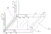
a height-adjustable foldable network topology troubleshooting tool support comprises a pair of angle iron support rods and is characterized in that the angle iron support rods comprise upper angle iron support rods 4 and lower angle iron support rods 9, the middle parts of the upper angle iron support rods 4 are provided with communicated elliptical holes 3 and semicircular holes 7, the lower ends of the upper angle iron support rods 4 are connected with the rear ends of the lower angle iron support rods 9, one ends of support plates 2, close to the upper angle iron support rods 4, are provided with long shafts 10, two ends of each long shaft 10 are supported in corresponding bearings 8, the bearings 8 are fixed at the rear ends of the lower angle iron support rods 9, and two side edges of each support plate 2 are movably supported on the lower angle iron support rods 9; the surface of the supporting plate 2 is provided with an insulating rubber strip 5, the front part of the supporting plate 2 is provided with a baffle 6, and the whole bracket part is hung into an expansion screw with a proper height of the wall body through an oval hole 3 and hung on the expansion screw in the wall body through a semicircular hole 7 so as to form a fixed structure.
The diameter of the elliptical hole 3 in the middle of the upper angle iron support rod 4 is larger than that of the semicircular hole 7 so as to be hung on different heights of the wall body conveniently.
And a locking screw 1 is arranged at the front end of the lower angle iron supporting rod 9.
The utility model has the advantages that:
the utility model has the advantages of reasonable structure, easy operation, safety use the utility model discloses can effectively avoid the staff to lift the tester with the arm, not occupy the computer lab finite space and settle the table chair when alleviating staff's hand fatigue, avoided unnecessary work, improve work efficiency.
Drawings
Fig. 1 is a schematic structural diagram of the present invention.
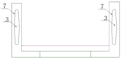
Fig. 2 is a left side view of fig. 1.
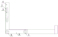
Fig. 3 is a front view of fig. 1.
In the figure: 1. a screw; 2. a support plate; 3. an elliptical hole; 4. an upper angle iron support bar; 5. an insulating rubber strip; 6. a baffle plate; 7. a semi-circular aperture; 8. a rotatable bearing; 9. the angle iron support bar.
Detailed Description
The invention will be further explained with reference to the drawings and the specific embodiments.
As shown in fig. 1-3.
A height-adjustable foldable network topology troubleshooting tool support comprises a pair of angle iron support rods and a support plate at the lower end of each angle iron support rod, wherein the support plate can be made of plastics, steel materials or wood materials, each angle iron support rod comprises an upper angle iron support rod 4 and a lower angle iron support rod 9, the lower end of each upper angle iron support rod 4 is connected with the rear end of each lower angle iron support rod 9 in a welding mode to form a whole, an oval hole 3 and a semicircular hole 7 are formed in the middle of each upper angle iron support rod 4, the lower end of each upper angle iron support rod 4 is connected with the rear end of each lower angle iron support rod 9, a long shaft 10 is installed at one end, close to each upper angle iron support rod 4, of each support plate 2, two ends of each long shaft 10 are supported in corresponding bearings 8, the end faces of the bearings 8 are fixedly welded to the rear; the surface of the supporting plate 2 is provided with an insulating rubber strip 5, the front part of the supporting plate 2 is provided with a baffle 6, and the whole bracket part is hung into an expansion screw with a proper height of the wall body through an oval hole 3 and hung on the expansion screw in the wall body through a semicircular hole 7 so as to form a fixed structure. The surface of the supporting plate 2 is provided with an insulating rubber strip 5, the front part of the supporting plate 2 is provided with a baffle 6, and the whole bracket part can be hung in an expansion screw with a proper height of the wall body through the oval hole 3 and hung in the semicircular hole 7 to form a fixed structure, as shown in figure 1. The diameter of the elliptical hole 3 in the middle of the upper angle iron support rod 4 is larger than that of the semicircular hole 7, and the upper angle iron support rod can be hung on a wall body at different heights, as shown in figure 2. The rotatable bearing 8 is mounted at the bottom of the support plate 2, as shown in fig. 3.
The utility model discloses a use method is:
firstly, a fixed expansion screw which is suitable for the height of a worker on a wall body is selected through the oval hole 3, after the expansion screw is selected to be at a proper height, the expansion screw is sleeved into the oval hole 3 with a larger hole diameter, and then the expansion screw slides upwards into the semicircular hole 7 to be clamped on the expansion screw which is fixed on the wall body, so that a stable structure is formed. When the staff need use, direct manual pulling layer board 2 both sides put down layer board 2 and place in on lower angle iron bracing piece 9 and fix a position with locking screw 1, then when the staff used the tester, can place the tester on layer board 2, need not hold in the palm the tester with the hand for a long time, liberated both hands. The bottom insulating rubber strip 5 prevents the tester from sliding on the pallet 2. After finishing using, the staff can take out the tester, loosen locking screw 1, paste the wall body with baffle 2 from bottom to top again, reach the effect of accomodating of practicing thrift the space.
Claims (3)
1. A height-adjustable foldable network topology troubleshooting tool support comprises a pair of angle iron supporting rods and is characterized in that the angle iron supporting rods comprise upper angle iron supporting rods (4) and lower angle iron supporting rods (9), a through elliptical hole (3) and a semicircular hole (7) are formed in the middle of each upper angle iron supporting rod (4), the lower ends of the upper angle iron supporting rods (4) are connected with the rear ends of the lower angle iron supporting rods (9), a long shaft (10) is installed at one end, close to the upper angle iron supporting rods (4), of a supporting plate (2), two ends of each long shaft (10) are supported in corresponding bearings (8), the bearings (8) are fixed at the rear ends of the lower angle iron supporting rods (9), and two side edges of the supporting plate (2) are movably supported on the lower angle iron supporting rods (9); insulating rubber strips (5) are arranged on the surface of the supporting plate (2), a baffle (6) is arranged at the front part of the supporting plate (2), and the whole support part is hung into expansion screws with proper height in the wall body through the oval holes (3) and hung on the expansion screws in the wall body through the semicircular holes (7) to form a fixed structure.
2. The height-adjustable foldable network topology troubleshooting tool support of claim 1, characterized in that the diameter of the oval hole (3) in the middle of the upper angle iron support bar (4) is larger than that of the semicircular hole (7) so as to be hung on different heights of the wall body.
3. The height-adjustable and foldable network topology troubleshooting tool support of claim 1 characterized in that the lower angle iron support bar (9) is mounted with a locking screw (1) at the front end.
Priority Applications (1)
| Application Number | Priority Date | Filing Date | Title |
|---|---|---|---|
| CN202022506405.6U CN213512985U (en) | 2020-11-03 | 2020-11-03 | Height-adjustable foldable network topology troubleshooting tool support |
Applications Claiming Priority (1)
| Application Number | Priority Date | Filing Date | Title |
|---|---|---|---|
| CN202022506405.6U CN213512985U (en) | 2020-11-03 | 2020-11-03 | Height-adjustable foldable network topology troubleshooting tool support |
Publications (1)
| Publication Number | Publication Date |
|---|---|
| CN213512985U true CN213512985U (en) | 2021-06-22 |
Family
ID=76420223
Family Applications (1)
| Application Number | Title | Priority Date | Filing Date |
|---|---|---|---|
| CN202022506405.6U Active CN213512985U (en) | 2020-11-03 | 2020-11-03 | Height-adjustable foldable network topology troubleshooting tool support |
Country Status (1)
| Country | Link |
|---|---|
| CN (1) | CN213512985U (en) |
-
2020
- 2020-11-03 CN CN202022506405.6U patent/CN213512985U/en active Active
Similar Documents
| Publication | Publication Date | Title |
|---|---|---|
| CN213512985U (en) | Height-adjustable foldable network topology troubleshooting tool support | |
| CN203459861U (en) | Clamp for fixing multi-specification test piece, allowing multiple positions to be welded, and allowing two persons to weld simultaneously | |
| CN211590006U (en) | Panel processing operation panel | |
| CN204349307U (en) | Middle circuit breaker moves apparatus for examination and repair | |
| CN204657993U (en) | Holding device | |
| CN201854908U (en) | Novel fabric wardrobe frame structure | |
| CN207296862U (en) | A kind of house hydropower installation folding device | |
| CN207523184U (en) | A kind of adjustable workbench for printing equipment | |
| CN210493264U (en) | Engineering cost apparatus frame | |
| CN203992954U (en) | A kind of revolving door crossbeam processing adjustment rack | |
| CN206967427U (en) | A kind of special mobile inspection rack of information machine room | |
| CN207914862U (en) | A kind of gas-insulated lines Inflatable cabinet body auxiliary welding equipment | |
| CN208480806U (en) | Architectural design drawing table | |
| CN208867763U (en) | A kind of storage shelf of mathematics drawing tool | |
| CN213550466U (en) | Portable engineering cost operation panel | |
| CN218428256U (en) | Adjustable radiator detection table | |
| CN106181915B (en) | A kind of Collapsible multifunctional carves table | |
| CN207942329U (en) | A kind of small-sized fixing device of craftwork processing | |
| CN220696804U (en) | Multifunctional adjustable sample adding support | |
| CN109944050A (en) | A kind of fabric cutting table structure | |
| CN212822774U (en) | A quick perforating device for stainless steel processing | |
| CN220331251U (en) | On-site debugging workbench | |
| CN220494526U (en) | Workbench for electronic information system integration | |
| CN217307031U (en) | Strutting arrangement and outdoor high-low voltage distribution cabinet | |
| CN211833399U (en) | All-round seal art work four-people table |
Legal Events
| Date | Code | Title | Description |
|---|---|---|---|
| GR01 | Patent grant | ||
| GR01 | Patent grant |