CN213498517U - Fixed frock is used in thrust wheel production - Google Patents
Fixed frock is used in thrust wheel production Download PDFInfo
- Publication number
- CN213498517U CN213498517U CN202021889718.8U CN202021889718U CN213498517U CN 213498517 U CN213498517 U CN 213498517U CN 202021889718 U CN202021889718 U CN 202021889718U CN 213498517 U CN213498517 U CN 213498517U
- Authority
- CN
- China
- Prior art keywords
- fixed
- workbench
- thrust wheel
- sliding
- clamping head
- Prior art date
- Legal status (The legal status is an assumption and is not a legal conclusion. Google has not performed a legal analysis and makes no representation as to the accuracy of the status listed.)
- Active
Links
Images


Abstract
The utility model discloses a thrust wheel production is with fixed frock, include: the fixture comprises supporting plates and a workbench, wherein two supporting plates are symmetrically fixed at two ends of the bottom of the workbench, a fixed rod is arranged on the upper surface of one end of the workbench, an adjusting mechanism is arranged on the upper surface of the other end of the workbench, the adjusting mechanism is in transmission connection with a movable plate, sliding mechanisms are movably connected at two ends of the movable plate, a longitudinal clamping mechanism is arranged at the position, close to the adjusting mechanism, of the center of the movable plate, a transverse clamping mechanism is arranged at the position, close to the fixed rod, of the center of the movable plate, a lower clamping head is arranged below the transverse clamping mechanism on the upper surface of the workbench, a lower clamping block is arranged below the longitudinal clamping mechanism on the upper surface of the workbench, the fixture is used for producing the thrust wheel, and is stable in structure, simple in operation, capable of longitudinally clamping and transversely clamping the thrust wheel and capable of processing the thrust wheel, the efficiency is high.
Description
Technical Field
The utility model relates to a processing technology field of thrust wheel especially relates to a fixed frock is used in production of thrust wheel.
Background
The thrust wheel is one of crawler-type engineering machine chassis four-wheel one-band, its main function is supporting the weight of excavator and bull-dozer, let the track advance along the wheel, the thrust wheel is in the production course of working, need polish the processing to the thrust wheel, in the in-process of polishing the processing to the thrust wheel, need use a fixed frock to fix the thrust wheel, traditional fixed mode mainly is to screw up the bolt by the manual work and realizes fixing, waste time and energy, sometimes exert oneself inequality and probably lead to fixed insecure, therefore, it solves above-mentioned technical problem with fixed frock to be necessary to provide a new thrust wheel production.
SUMMERY OF THE UTILITY MODEL
In order to solve the technical problem, the utility model provides an it is electronic, easy operation, stable in structure, can vertical centre gripping and horizontal centre gripping thrust wheel production with fixed frock.
The utility model provides a thrust wheel production is with fixed frock includes: backup pad and workstation, the bottom symmetry at workstation both ends is fixed with two backup pads, top surface one side of workstation is fixed with the dead lever, the workstation top surface is located installs adjusting mechanism of adjusting device workspace with one side of dead lever symmetry, the adjusting mechanism transmission is connected with the movable plate, the equal swing joint in both ends of movable plate has slide mechanism, the center of movable plate is close to adjusting mechanism's position and installs indulge fixture, and indulges fixture's bottom and fix at the workstation upper surface, horizontal fixture is installed to the position that is close to the dead lever at movable plate center, and the upper surface at the workstation is fixed to horizontal fixture's bottom.
Preferably, adjustment mechanism includes packaging shell, stabilizer bar, rotating electrical machines, fixed plate, threaded rod and threaded sleeve, the one end upper surface of workstation is fixed with the packaging shell, the stabilizer bar is installed to the inner wall of packaging shell, the inside top of packaging shell is fixed with the fixed plate, the fixed plate is fixed connection with the stabilizer bar, the inside upper surface that is located the fixed plate of packaging shell has the rotating electrical machines, the output shaft of rotating electrical machines is fixed with the threaded rod, the threaded sleeve has been cup jointed to the screw thread on the threaded rod, the threaded sleeve is fixed with the movable plate.
Preferably, indulge fixture include connecting axle, compression spring, first dashpot, go up grip block and lower grip block, the fixed position that the center of movable plate is close to adjustment mechanism has the connecting axle, the connecting axle has last grip block through compression spring elastic connection, go up and seted up first dashpot in the grip block, and connecting axle and first dashpot slip grafting, the below that the upper surface of workstation is located last grip block is fixed with last grip block structure complex lower grip block.
Preferably, the horizontal clamping mechanism comprises a fixed shaft, a compression spring, a second buffer groove, an upper clamping head and a lower clamping head, the fixed shaft is fixed at a position, close to the fixed shaft, of the center of the moving plate, the compression spring is fixed at the end of the fixed shaft, the fixed shaft is elastically connected with the upper clamping head through the compression spring, the second buffer groove is formed in the upper clamping head, the fixed shaft is in sliding insertion with the second buffer groove, and the lower clamping head matched with the upper clamping head is fixed below the upper clamping head on the upper surface of the workbench.
Preferably, the sliding mechanism comprises a sliding groove and a sliding block, the sliding blocks are fixed at two ends of the moving plate, the sliding grooves matched with the sliding block structures are formed in the fixed rod and the stabilizer bar, and the sliding blocks are connected with the sliding grooves in a sliding mode.
Preferably, the bottom of the upper clamping head and the top of the lower clamping head are arc-shaped.
Compared with the prior art, the utility model provides a thrust wheel production is with fixed frock has following beneficial effect:
when the device is used, the thrust wheel is firstly placed on the lower clamping head or the lower clamping block, the rotating motor is started, the vertical clamping mechanism and the horizontal clamping mechanism can be adjusted to move up and down under the action of the adjusting mechanism and the sliding mechanism, the vertical clamping mechanism can be matched with the lower clamping block to fix two ends of the thrust wheel for processing, the horizontal clamping mechanism can be matched with the lower clamping head to fix the side body of the thrust wheel, when the upper clamping block of the vertical clamping mechanism is in extrusion contact with the thrust wheel or the upper clamping head of the horizontal clamping mechanism is in extrusion contact with the thrust wheel, the rotating motor is ready to be closed at any time, the rotating motor is closed after the thrust wheel is fixed and stable, then the thrust wheel is processed, the rotating motor is started after the processing, the vertical clamping mechanism and the horizontal clamping mechanism move upwards, after the vertical clamping mechanism and the horizontal clamping mechanism move upwards for a certain distance, the rotating motor is started to fix the thrust wheel, repeated such operation can carry out diversified processing to the thrust wheel, and after the processing, start the rotating electrical machines, indulge fixture and violently fixture and thrust wheel separation, take out the thrust wheel of processing can, repeated operation just can carry out the course of working of next thrust wheel, and this kind of fixed frock is used in thrust wheel production, stable in structure, easy operation can vertically centre gripping and horizontal centre gripping thrust wheel, can also diversely process the thrust wheel, and is efficient.
Drawings
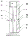
Fig. 1 is a schematic view of the overall structure provided by the present invention;
fig. 2 is a schematic view of an adjusting mechanism provided by the present invention;
fig. 3 is a schematic view of a horizontal clamping mechanism provided by the present invention;
fig. 4 is a schematic view of a longitudinal clamping mechanism provided by the present invention;
fig. 5 is a schematic view of the sliding mechanism provided by the present invention.
Reference numbers in the figures: 1. a support plate; 2. a work table; 3. an adjustment mechanism; 31. packaging the shell; 32. a stabilizer bar; 33. a rotating electric machine; 34. a fixing plate; 35. a threaded rod; 36. a threaded sleeve; 4. a longitudinal clamping mechanism; 41. a connecting shaft; 42. a pressure spring; 43. a first buffer tank; 44. an upper clamping block; 45. a lower clamping block; 5. moving the plate; 6. a horizontal clamping mechanism; 61. a fixed shaft; 62. a compression spring; 63. a second buffer tank; 64. an upper clamping head; 65. a lower clamping head; 7. a sliding mechanism; 71. a chute; 72. a slider; 8. and (5) fixing the rod.
Detailed Description
The present invention will be further described with reference to the accompanying drawings and embodiments.
Please refer to fig. 1, fig. 2, fig. 3, fig. 4 and fig. 5 in combination, wherein fig. 1 is a schematic diagram of an overall structure provided by the present invention; fig. 2 is a schematic structural diagram of an adjusting mechanism provided by the present invention; fig. 3 is a schematic structural view of the longitudinal clamping mechanism provided by the present invention; fig. 4 is a schematic structural view of a horizontal clamping mechanism provided by the present invention; fig. 5 is a schematic structural view of the sliding mechanism provided by the present invention. Thrust wheel production includes with fixed frock: a support plate 1 and a table 2.
In the specific implementation process, as shown in fig. 1 and 2, two support plates 1 are symmetrically fixed at the bottoms of two ends of a workbench 2, a fixed rod 8 is fixed at one side of the top surface of the workbench 2, an adjusting mechanism 3 for adjusting the working space of the device is installed at one side of the top surface of the workbench 2, the adjusting mechanism 3 is in transmission connection with a moving plate 5, two ends of the moving plate 5 are both movably connected with sliding mechanisms 7, a longitudinal clamping mechanism 4 is installed at the center of the moving plate 5 close to the adjusting mechanism 3, the bottom of the longitudinal clamping mechanism 4 is fixed on the upper surface of the workbench 2, a transverse clamping mechanism 6 is installed at the center of the moving plate 5 close to the fixed rod 8, the bottom of the transverse clamping mechanism 6 is fixed on the upper surface of the workbench 2, the support plates 1 play a role in supporting and stabilizing the workbench 2, and the workbench 2 provides an operation space for processing of a supporting wheel, the rotating motor 33 is started, the longitudinal clamping mechanism 4 and the transverse clamping mechanism 6 can be adjusted to move up and down under the action of the adjusting mechanism 3, the moving plate 5 and the sliding mechanism 7, the thrust wheel can be fixed when the longitudinal clamping mechanism 4 and the transverse clamping mechanism 6 move down, and the fixed state of the thrust wheel can be released when the longitudinal clamping mechanism 4 and the transverse clamping mechanism 6 move up, and the thrust wheel is rotated to process the thrust wheel in multiple directions.
Referring to fig. 1 and 2, the adjusting mechanism 3 includes a packaging shell 31, a stabilizer bar 32, a rotating motor 33, a fixing plate 34, a threaded rod 35 and a threaded sleeve 36, the packaging shell 31 is fixed on the upper surface of one end of the worktable 2, the stabilizer bar 32 is installed on the inner wall of the packaging shell 31, the fixing plate 34 is fixed above the inside of the packaging shell 31, the fixing plate 34 and the stabilizer bar 32 are fixedly connected, the rotating motor 33 is installed on the upper surface of the fixing plate 34 inside the packaging shell 31, the threaded rod 35 is fixed on the output shaft of the rotating motor 33, the threaded sleeve 36 is sleeved on the threaded rod 35 in a threaded manner, the moving plate 5 is fixed on the threaded sleeve 36, the rotating motor 33 is turned on, the threaded rod 35 coaxially connected with the output end of the rotating motor 33 rotates to drive the threaded sleeve 36 to move up and down on the threaded rod 35, so, and finally, the moving plate 5 drives the longitudinal clamping mechanism 4 and the transverse clamping mechanism 6 to move up and down, so that the longitudinal clamping mechanism 4 and the transverse clamping mechanism 6 are adjusted up and down.
Referring to fig. 1 and 3, the longitudinal clamping mechanism 4 includes a connecting shaft 41, a pressure spring 42, a first buffer slot 43, an upper clamping block 44 and a lower clamping block 45, the position of the center of the moving plate 5 near the adjusting mechanism 3 is fixed with the connecting shaft 41, the connecting shaft 41 is elastically connected with the upper clamping block 44 through the pressure spring 42, the upper clamping block 44 is internally provided with the first buffer slot 43, the connecting shaft 41 is inserted with the first buffer slot 43 in a sliding manner, the lower clamping block 45 structurally matched with the upper clamping block 44 is fixed on the upper surface of the worktable 2 below the upper clamping block 44, the longitudinal clamping mechanism 4 can move up and down under the action of the adjusting mechanism 3 and the moving plate 5, when the longitudinal clamping mechanism 4 moves down to press and contact with the thrust wheel, the pressure spring 42 is continuously pressed by the downward movement of the adjusting mechanism 3 and the connecting shaft 5, the extrusion force of the longitudinal clamping mechanism 4 to the thrust wheel is slowly increased, so that the thrust wheel is effectively prevented from being damaged due to the fact that the thrust wheel is stressed violently.
Referring to fig. 1 and 4, the horizontal clamping mechanism 6 includes a fixed shaft 61, a compression spring 62, a second buffer groove 63, an upper clamping head 64 and a lower clamping head 65, the fixed shaft 61 is fixed at a position of the center of the moving plate 5 near the fixed rod 8, the compression spring 62 is fixed at an end of the fixed shaft 61, the upper clamping head 64 is elastically connected to the fixed shaft 61 through the compression spring 62, the second buffer groove 63 is opened inside the upper clamping head 64, the fixed shaft 61 is slidably inserted into the second buffer groove 63, the lower clamping head 65 structurally matched with the upper clamping head 64 is fixed on the upper surface of the worktable 2 below the upper clamping head 64, the horizontal clamping mechanism 6 can move up and down under the action of the adjusting mechanism 3 and the moving plate 5, when the horizontal clamping mechanism 6 moves down to press and contact the supporting wheels, under the action of the adjusting mechanism 3 and the moving plate 5, the fixed shaft 61 continues to move downwards to extrude the compression spring 62, and the extrusion force of the longitudinal clamping mechanism 4 to the thrust wheel is slowly increased, so that the thrust wheel is effectively prevented from being damaged due to the fact that the thrust wheel is stressed violently.
Referring to fig. 1 and 5, the sliding mechanism 7 includes a sliding slot 71 and a sliding block 72, the sliding block 72 is fixed at both ends of the moving plate 5, the sliding slot 71 structurally matched with the sliding block 72 is formed inside the fixed rod 8 and the stabilizer bar 32, the sliding block 72 is slidably connected with the sliding slot 71, the sliding block 72 is fixed at both ends of the moving plate 5, and the sliding block 72 is slidably connected with the sliding slot 71, so that the moving plate 5 can move up and down in the sliding slot 71 along with the sliding block 72 under the action of the adjusting mechanism 3.
Referring to fig. 1 and 3, the bottom of the upper clamping head 64 and the top of the lower clamping head 65 are arc-shaped, and the bottom of the upper clamping head 64 and the top of the lower clamping head 65 are arc-shaped to provide a plurality of stress points for clamping the supporting wheel, so that the clamping is more stable and the supporting wheel is prevented from falling off.
The working principle is as follows: when the device is used, the thrust wheel is firstly placed on the lower clamping head 65 or the lower clamping block 45, the rotating motor 33 is started, the threaded rod 35 rotates to drive the threaded sleeve 36 to move downwards, the threaded sleeve 36 drives the moving plate 5 to move downwards so as to drive the longitudinal clamping mechanism 4 and the transverse clamping mechanism 6 to move downwards, the longitudinal clamping mechanism 4 can be matched with the lower clamping block 45 to fix two ends of the thrust wheel and process the thrust wheel, the transverse clamping mechanism 6 can be matched with the lower clamping head 65 to fix the side body of the thrust wheel, when the upper clamping block 44 of the longitudinal clamping mechanism 4 is in extrusion contact with the thrust wheel or the upper clamping head 64 of the transverse clamping mechanism 6 is in extrusion contact with the thrust wheel, the rotating motor 33 is ready to be closed at any time, after the thrust wheel is fixed and stable, the rotating motor 33 is closed, then the thrust wheel is processed, after the processing, the rotating motor 33 is started, the threaded sleeve 36 moves upwards to drive the moving plate 5 to move upwards, thereby indulge fixture 4 and violently fixture 6 rebound in the drive, treat to indulge fixture 4 and violently fixture 6 and shift up after certain distance, rotate behind the thrust wheel and start rotating electrical machines 33 and fix it, it is repeated so operation can carry out diversified processing to the thrust wheel, after processing, start rotating electrical machines 33, go up grip block 44 or go up the holding head 64 and the separation of thrust wheel, it can to take out the thrust wheel that has processed, repeated operation just can carry out the course of working of next thrust wheel.
The above only is the embodiment of the present invention, not limiting the scope of the present invention, all the equivalent structures or equivalent processes of the present invention are used in the specification and the attached drawings, or directly or indirectly applied to other related technical fields, and the same principle is included in the protection scope of the present invention.
Claims (6)
1. The utility model provides a thrust wheel production is with fixed frock, includes: a supporting plate (1) and a workbench (2), wherein the two supporting plates (1) are symmetrically fixed at the bottoms of the two ends of the workbench (2), it is characterized in that a fixed rod (8) is fixed on one side of the top surface of the workbench (2), the top surface of the workbench (2) is provided with an adjusting mechanism (3) for adjusting the working space of the device at one side symmetrical to the fixed rod (8), the adjusting mechanism (3) is in transmission connection with a moving plate (5), two ends of the moving plate (5) are both movably connected with sliding mechanisms (7), a longitudinal clamping mechanism (4) is arranged at the position, close to the adjusting mechanism (3), of the center of the moving plate (5), the bottom of the longitudinal clamping mechanism (4) is fixed on the upper surface of the workbench (2), a transverse clamping mechanism (6) is arranged at the position, close to the fixed rod (8), of the center of the moving plate (5), and the bottom of the transverse clamping mechanism (6) is fixed on the upper surface of the workbench (2).
2. The fixed tooling for the production of the thrust wheel according to claim 1, wherein the adjusting mechanism (3) comprises a packaging shell (31), a stabilizer bar (32), a rotating motor (33), a fixed plate (34), a threaded rod (35) and a threaded sleeve (36), a packaging shell (31) is fixed on the upper surface of one end of the workbench (2), a stabilizing rod (32) is installed on the inner wall of the packaging shell (31), a fixing plate (34) is fixed above the inside of the packaging shell (31), the fixing plate (34) is fixedly connected with the stabilizer bar (32), a rotating motor (33) is arranged on the upper surface of the fixing plate (34) in the packaging shell (31), the output shaft of rotating electrical machines (33) is fixed with threaded rod (35), threaded sleeve (36) has been cup jointed to the screw thread on threaded rod (35), threaded sleeve (36) are fixed with movable plate (5).
3. The fixed tooling for the thrust wheel production according to claim 1, wherein the longitudinal clamping mechanism (4) comprises a connecting shaft (41), a pressure spring (42), a first buffer groove (43), an upper clamping block (44) and a lower clamping block (45), the connecting shaft (41) is fixed at a position, close to the adjusting mechanism (3), of the center of the moving plate (5), the connecting shaft (41) is elastically connected with the upper clamping block (44) through the pressure spring (42), the first buffer groove (43) is formed in the upper clamping block (44), the connecting shaft (41) is in sliding insertion connection with the first buffer groove (43), and the lower clamping block (45) structurally matched with the upper clamping block (44) is fixed below the upper clamping block (44) on the upper surface of the workbench (2).
4. The fixed tooling for the production of the thrust wheel according to claim 1, wherein the transverse clamping mechanism (6) comprises a fixed shaft (61), a compression spring (62), a second buffer groove (63), an upper clamping head (64) and a lower clamping head (65), a fixed shaft (61) is fixed at the position of the center of the moving plate (5) close to the fixed rod (8), a compression spring (62) is fixed at the end part of the fixed shaft (61), the fixed shaft (61) is elastically connected with an upper clamping head (64) through the compression spring (62), a second buffer groove (63) is arranged inside the upper clamping head (64), and the fixed shaft (61) is inserted with the second buffer groove (63) in a sliding manner, and a lower clamping head (65) structurally matched with the upper clamping head (64) is fixed on the upper surface of the workbench (2) below the upper clamping head (64).
5. The fixed tooling for the thrust wheel production according to claim 1, wherein the sliding mechanism (7) comprises a sliding groove (71) and a sliding block (72), the sliding block (72) is fixed at both ends of the moving plate (5), the sliding groove (71) structurally matched with the sliding block (72) is formed in each of the fixed rod (8) and the stabilizer bar (32), and the sliding block (72) is slidably connected with the sliding groove (71).
6. The fixed tooling for producing the thrust wheel according to claim 4, wherein the bottom of the upper clamping head (64) and the top of the lower clamping head (65) are arc-shaped.
Priority Applications (1)
| Application Number | Priority Date | Filing Date | Title |
|---|---|---|---|
| CN202021889718.8U CN213498517U (en) | 2020-09-02 | 2020-09-02 | Fixed frock is used in thrust wheel production |
Applications Claiming Priority (1)
| Application Number | Priority Date | Filing Date | Title |
|---|---|---|---|
| CN202021889718.8U CN213498517U (en) | 2020-09-02 | 2020-09-02 | Fixed frock is used in thrust wheel production |
Publications (1)
| Publication Number | Publication Date |
|---|---|
| CN213498517U true CN213498517U (en) | 2021-06-22 |
Family
ID=76444127
Family Applications (1)
| Application Number | Title | Priority Date | Filing Date |
|---|---|---|---|
| CN202021889718.8U Active CN213498517U (en) | 2020-09-02 | 2020-09-02 | Fixed frock is used in thrust wheel production |
Country Status (1)
| Country | Link |
|---|---|
| CN (1) | CN213498517U (en) |
-
2020
- 2020-09-02 CN CN202021889718.8U patent/CN213498517U/en active Active
Similar Documents
| Publication | Publication Date | Title |
|---|---|---|
| CN112659276B (en) | Wood system cylinder drilling equipment of polishing for wood working | |
| CN109140158A (en) | A kind of mainframe computer cabinet shock-proof protector | |
| CN213531697U (en) | Part clamping device is used in machine part processing | |
| CN213968681U (en) | Workpiece fixing device of punching and shearing machine | |
| CN116117649A (en) | Forging and polishing equipment for iron-chromium-boron cast wear-resistant alloy and application method thereof | |
| CN213498517U (en) | Fixed frock is used in thrust wheel production | |
| CN206047151U (en) | Axle class punching tooling | |
| CN219053634U (en) | Machining clamp for automobile steering knuckle | |
| CN111251098A (en) | Panel fixing device for auto repair | |
| CN114952657B (en) | Reversible toughened glass processing fixing device and application method thereof | |
| CN218252989U (en) | Automobile machinery part processingequipment | |
| CN207887932U (en) | A kind of automobile rocker axis borehole drill construction automatic-lifting type drilling mobile mechanism | |
| CN215470980U (en) | Machining is with damping workbench who has fixing device | |
| CN215785879U (en) | Box transformer substation shell rapid bending processing equipment | |
| CN212420769U (en) | Polishing equipment for brake pad | |
| CN205519771U (en) | Bar location drilling equipment | |
| CN213364662U (en) | Liquid chromatograph | |
| CN210937213U (en) | Drilling equipment is used in production of electric power staple bolt | |
| CN111391396A (en) | Support device for hydraulic press workbench | |
| CN220332733U (en) | Gear machining turnover vehicle | |
| CN220680713U (en) | Development table for adjustable mechanical equipment | |
| CN213859259U (en) | Multifunctional sucker mechanical arm | |
| CN220216792U (en) | Processing device for automobile active suspension control arm | |
| CN216176338U (en) | Front cabin lock body reverse riveting tool | |
| CN220515967U (en) | Auxiliary pressing device for bushing installation |
Legal Events
| Date | Code | Title | Description |
|---|---|---|---|
| GR01 | Patent grant | ||
| GR01 | Patent grant |