Injection mold is used in production of car navigation panel
Technical Field
The utility model belongs to the technical field of heat abstractor, concretely relates to injection mold is used in production of car navigation panel.
Background
An injection mold is a tool for producing plastic products; and is also a tool for giving the plastic product complete structure and accurate dimension. Injection molding is a process used to mass produce parts of some complex shapes. Specifically, the plastic melted by heating is injected into a mold cavity from an injection molding machine at high pressure, and a formed product is obtained after cooling and solidification.
At present, in the process of producing an injection mold for a plastic automobile navigation panel, after plastic is injected into the injection mold, the plastic in the injection mold needs to be cooled for a certain time, so that a product is molded. But not only have the waste time among the prior art, great reduction product production's efficiency moreover to after the product shaping, the product can be hugged closely on the inner wall of die cavity, and when the workman used professional instrument to press from both sides the finished product out, the condition problem that the plastic product damaged appears easily
SUMMERY OF THE UTILITY MODEL
The utility model provides an injection mold is used in production of car navigation panel has solved among the prior art injection mold and has injected the plastic and receive, and the long and difficult heat dissipation of mould function in-process of cooling time shortens the life scheduling problem of machine easily.
The technical scheme of the utility model is realized like this:
an injection mold for producing an automobile navigation panel comprises an injection mold body and a heat dissipation assembly, wherein the heat dissipation assembly is tightly buckled with the injection mold body through a telescopic rod;
the heat dissipation assembly comprises water pipes, the water pipes are evenly distributed inside the heat dissipation assembly, one side of the upper end of each water pipe is fixedly connected with the water storage tank, and a plurality of fixing buckles are movably mounted on the outer sides of the water pipes.
Preferably, the upper end of the water pipe is fixedly connected with the water inlet, and a water outlet is formed in one side, close to the telescopic rod.
Preferably, the injection mold body comprises a female mold and a male mold, the male mold is tightly buckled with the female mold through the telescopic rod, one end of the female mold is connected with a rotating shaft, and the upper end of the rotating shaft is fixedly connected with an injection molding opening.
Preferably, one side of the rotating shaft is fixedly connected with a storage box, and a plurality of feeding holes are formed in the storage box.
Preferably, the heat dissipation net is arranged on the outer side of the female die, and the female die is provided with a limiting block.
Preferably, the injection mold body comprises a base, and the base is connected with the heat dissipation assembly in a sliding mode through a clamping groove.
Preferably, the interlayer of the base and the universal wheels forms a cabinet.
The utility model has the advantages that:
the utility model discloses a telescopic link and radiator unit interconnect, the water pipe among the radiator unit is through fixed knot and the inside tight lock of radiator unit for the more quick heat that gives off of injection mold when the function, prolong its life, and through water-cooling heat dissipation, injection mold's the matrix drawing of patterns more easily.
Drawings
In order to more clearly illustrate the embodiments of the present invention or the technical solutions in the prior art, the drawings used in the description of the embodiments or the prior art will be briefly described below, it is obvious that the drawings in the following description are only some embodiments of the present invention, and for those skilled in the art, other drawings can be obtained according to these drawings without creative efforts.
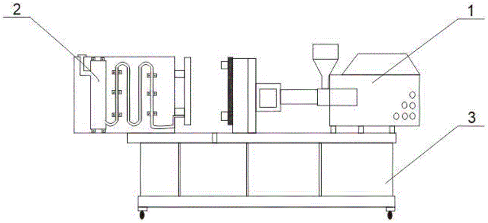
FIG. 1 is a schematic view of the whole structure of the injection mold of the present invention;
FIG. 2 is a schematic view of the heat dissipation device of the present invention;
fig. 3 is the front structural schematic diagram of the injection mold of the present invention.
Wherein, 1, injection molding a mould body; 101. a female die; 1011. an injection molding port; 1012. a rotating shaft; 1013. a limiting block; 1014. a heat-dissipating web; 1015. a feed port; 102. a male die; 1021. a telescopic rod; 2. a heat dissipating component; 201. a water inlet; 202. a water pipe; 203. a water storage tank; 204. a fixing buckle; 205. a water outlet; 3. A base.
Detailed Description
The technical solutions in the embodiments of the present invention will be described clearly and completely with reference to the accompanying drawings in the embodiments of the present invention, and it is obvious that the described embodiments are only some embodiments of the present invention, not all embodiments. Based on the embodiments in the present invention, all other embodiments obtained by a person skilled in the art without creative work belong to the protection scope of the present invention.
Referring to fig. 1-3, an embodiment of the present invention provides an injection mold for producing an automobile navigation panel, including an injection mold body 1 and a heat dissipation assembly 2, wherein the heat dissipation assembly 2 is tightly fastened to the injection mold body 1 through a telescopic rod 1021;
the heat dissipation assembly 2 comprises a water pipe 202, the water pipe 202 is uniformly distributed inside the heat dissipation assembly 2, one side of the upper end of the water pipe 202 is fixedly connected with a water storage tank 203, and a plurality of fixing buckles 204 are movably mounted on the outer side of the water pipe 202.
The upper end of the water pipe 202 is fixedly connected with the water inlet 201, one side close to the telescopic rod 1021 is provided with the water outlet 205, the upper end close to the telescopic rod 1021 can not only cool the injection mold body 1, but also can demold the mold more easily, the injection mold body 1 comprises a female mold 101 and a male mold 102, the male mold 102 is tightly buckled with the female mold 101 through the telescopic rod 1021, one end of the female mold 101 is connected with the rotating shaft 1012, the rotating shaft 1012 can accelerate to enter the male mold 102, so that the mold is rapidly formed, the upper end of the rotating shaft 1012 is fixedly connected with the injection port 1011, the material can enter the injection port 1011 more rapidly, one side of the rotating shaft 1012 is fixedly connected with the storage box, and the storage box is provided with a plurality of feeding holes 1015, the injection port 1011 enters the rotating shaft 1012 to generate huge heat, the cooling is not easy, the heat of the mold, and master model 101 is provided with stopper 1013, the position of definite panel that can be more accurate for the mould unification and standardization, injection mold body 1 include base 3, and base 3 passes through draw-in groove and 2 sliding connection of radiator unit, and is whole more stable, and base 3 has formed the cupboard with the intermediate layer of universal wheel, is convenient for store, and is more convenient.
The working principle is as follows: the utility model discloses a rivers flow into water pipe 202 by water inlet 201, and water pipe 202 sets up in the inside of radiator unit 2 through fixed knot 204, not only can make the machine cool off more fast, can make the inside cleaner and tidier moreover; the male mold 102 is tightly fastened with the female mold 101 through the telescopic rod 1021, and under the telescopic condition of the telescopic rod 1021, the water flow of the water pipe 202 is sprayed onto the injection mold body 1 through the pressure of the spring, so that the mold is easy to demold.
The above description is only a preferred embodiment of the present invention, and should not be taken as limiting the invention, and any modifications, equivalent replacements, improvements, etc. made within the spirit and principle of the present invention should be included in the protection scope of the present invention.