CN213469913U - Numerical control cutting device for flat plate special-shaped groove - Google Patents
Numerical control cutting device for flat plate special-shaped groove Download PDFInfo
- Publication number
- CN213469913U CN213469913U CN202022417154.4U CN202022417154U CN213469913U CN 213469913 U CN213469913 U CN 213469913U CN 202022417154 U CN202022417154 U CN 202022417154U CN 213469913 U CN213469913 U CN 213469913U
- Authority
- CN
- China
- Prior art keywords
- cutting
- fixedly connected
- plate
- fixed block
- lead screw
- Prior art date
- Legal status (The legal status is an assumption and is not a legal conclusion. Google has not performed a legal analysis and makes no representation as to the accuracy of the status listed.)
- Active
Links
Images

Landscapes
- Arc Welding In General (AREA)
Abstract
The utility model discloses a dull and stereotyped abnormal shape groove numerical control cutting device, including the cutting bed, the upper end of cutting bed is provided with spacing fixture, and the upper end four corners fixedly connected with support column of cutting bed, four the same fixed frame of upper end fixedly connected with of support column, and the rectangle opening of intercommunication about the department sets up in the middle of fixed frame's the upper end, fixed frame's upper end is provided with the cutting adjustment mechanism corresponding with the cutting bed. The utility model discloses the cutting adjustment mechanism who sets up replaces the manual work to control the cutting torch and carries out cutting work, adapts to multi-direction removal regulation, and the accuracy when having improved the cutting has reduced the error of manual operation cutting, has reduced staff's work degree, has improved work efficiency, and spacing fixture's design is adapted to the centre gripping of not unidimensional panel simultaneously and is fixed, and stability when having guaranteed the panel cutting has improved application scope.
Description
Technical Field
The utility model relates to a cutting device technical field especially relates to a dull and stereotyped abnormal shape groove numerical control cutting device.
Background
In the field of cranes in China, hoisting machinery is usually operated outdoors, and is easily corroded and damaged after a long time, in order to weld workpieces and ensure the welding degree, molded surfaces machined by a machining method under ordinary conditions can be subjected to gas cutting when the requirement is not high.
However, in the actual use process of the conventional numerical control cutting device for the flat plate special-shaped groove, the cutting torch needs to be manually held to perform groove cutting, the labor intensity is high, meanwhile, the manual holding operation error is large, the accuracy is low, the plate is easy to shake when the groove cutting is performed, and a corresponding limiting clamping mechanism is not provided to ensure the stability of the cutting operation.
Disclosure of Invention
The utility model aims at solving the defects existing in the prior art and providing a flat plate special-shaped groove numerical control cutting device.
In order to achieve the above purpose, the utility model adopts the following technical scheme: the utility model provides a dull and stereotyped abnormal shape groove numerical control cutting device, includes the cutting bed, the upper end of cutting bed is provided with spacing fixture, and the upper end four corners department fixedly connected with support column, four of cutting bed the same fixed frame of upper end fixedly connected with of support column, and the rectangle opening of intercommunication about the department sets up in the middle of fixed frame's the upper end, fixed frame's upper end is provided with the cutting adjustment mechanism corresponding with the cutting bed.
Preferably, spacing fixture includes fixed plate of fixed connection symmetric distribution around the upper end of cutting bed, the lateral wall of fixed plate runs through and is provided with the threaded rod, the one end fixedly connected with rocking handle of cutting bed is kept away from to the threaded rod, and the one end rotation that the rocking handle was kept away from to the threaded rod is connected with spacing splint, and spacing splint sliding connection is in the upper end of cutting bed.
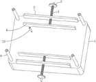
Preferably, the cutting adjustment mechanism includes the baffle of welding in fixed frame back wall upper end, the front side of baffle is opened and is equipped with spout one, and the place ahead of baffle is provided with bilateral symmetry's first fixed block and second fixed block, and the lower extreme of first fixed block and second fixed block respectively with the left and right corners upper end fixed connection of cutting bed.
Preferably, the front side of the first fixed block is provided with a first lead screw in a penetrating manner, one end, far away from the first fixed block, of the first lead screw is rotatably connected to the front side of the baffle, one end, far away from the baffle, of the first lead screw is fixedly connected with a first hand wheel, a first moving block is slidably sleeved on the annular surface of the first lead screw, a connecting plate is fixedly connected to the side wall of the first moving block and located right above the rectangular opening, and a second sliding groove which is communicated with the upper portion and the lower portion of the connecting plate is formed in a penetrating manner in the upper end of.
Preferably, a second lead screw penetrates through the side wall of the second fixed block, one end, far away from the second fixed block, of the second lead screw is rotatably connected to the side wall of the first fixed block, a second hand wheel is fixedly connected to one end, far away from the first fixed block, of the second lead screw, a second moving block is slidably sleeved on the annular surface of the second hand wheel, a connecting rod is fixedly connected to the rear side of the second moving block, and one end, far away from the second moving block, of the connecting rod is slidably connected to the inside of the first sliding groove.
Preferably, the annular surface of the connecting rod is slidably sleeved with a movable block, the upper end of the movable block is fixedly connected with a limiting slide rod, the limiting slide rod is slidably connected inside the second sliding groove, and the lower end of the movable block is fixedly provided with a cutting torch.
Compared with the prior art, the beneficial effects of the utility model are that:
1. the cutting adjusting mechanism replaces manual holding of the cutting torch to carry out cutting work, adapts to multi-directional movement adjustment, improves the accuracy in cutting, reduces errors of manual operation cutting, reduces the labor degree of workers and improves the working efficiency;
2. the design of the limiting clamping mechanism carries out opposite movement through the limiting clamping plates distributed in the front and the back, so that the clamping mechanism is suitable for clamping and fixing plates of different sizes, the stability of the plates during cutting is guaranteed, and the application range is widened.
Drawings
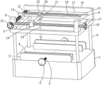
Fig. 1 is a schematic view of the structure of the present invention.
Fig. 2 is a schematic top view of the present invention.
Fig. 3 is a schematic view of the overlooking and sectioning structure of the present invention.
In the figure: 1. cutting table; 2. a fixing plate; 3. a threaded rod; 4. a limiting clamp plate; 5. a rocking handle; 6. a support pillar; 7. a fixed frame; 8. a first fixed block; 9. a second fixed block; 10. a baffle plate; 11. a first sliding chute; 12. a first lead screw; 13. a first hand wheel; 14. a first moving block; 15. a connecting plate; 16. a second chute; 17. a second lead screw; 18. a second hand wheel; 19. a second moving block; 20. a connecting rod; 21. a movable block; 22. a limiting slide bar; 23. a cutting torch is provided.
Detailed Description
The technical solutions in the embodiments of the present invention will be described clearly and completely with reference to the accompanying drawings in the embodiments of the present invention, and it is obvious that the described embodiments are only some embodiments of the present invention, not all embodiments.
Referring to fig. 1-3, a numerical control cutting device for flat irregular grooves comprises a cutting table 1, wherein a limiting clamping mechanism is arranged at the upper end of the cutting table 1, supporting columns 6 are fixedly connected at four corners of the upper end of the cutting table 1, the upper ends of the four supporting columns 6 are fixedly connected with a same fixed frame 7, and a rectangular opening which is communicated up and down is arranged in the middle of the upper end of the fixed frame 7, so that a cutting torch 23 can move freely, specifically, the limiting clamping mechanism comprises fixed plates 2 which are fixedly connected to the upper end of the cutting table 1 and are symmetrically distributed in the front and back direction, threaded rods 3 penetrate through the side walls of the fixed plates 2, a rocking handle 5 is fixedly connected to one end of each threaded rod 3, which is far away from the cutting table 1, a limiting clamping plate 4 is rotatably connected to one end of each, rocking handle 5 that distributes around rotating, and then make threaded rod 3 rotate, because sliding connection is injectd in cutting bed 1's upper end to spacing splint 4's lower extreme, and then distribute spacing splint 4 around driving and carry out steadily opposite direction and remove, it is fixed to stabilize the centre gripping to panel, and then the centre gripping that is adapted to not unidimensional panel is fixed, stability when having guaranteed the panel cutting has improved application scope.
Wherein, the front side of baffle 10 is opened and is equipped with spout 11, and is concrete, and the one end sliding connection that second movable block 19 was kept away from to connecting rod 20 is in the inside of spout 11, moves about second movable block 19, and through sliding with connecting rod 20 spacing in the inside of spout 11, and then improve connecting rod 20 and carry out the stability of translation.
Wherein, the upper end of the fixed frame 7 is provided with a cutting adjusting mechanism corresponding to the cutting table 1, concretely, the limiting clamping mechanism comprises a fixed plate 2 which is fixedly connected to the upper end of the cutting table 1 and is symmetrically distributed in the front and back direction, a threaded rod 3 is arranged on the side wall of the fixed plate 2 in a penetrating manner, one end of the threaded rod 3 far away from the cutting table 1 is fixedly connected with a rocking handle 5, one end of the threaded rod 3 far away from the rocking handle 5 is rotatably connected with a limiting clamp plate 4, the limiting clamp plate 4 is connected to the upper end of the cutting table 1 in a sliding manner, concretely, the cutting adjusting mechanism comprises a baffle plate 10 welded to the upper end of the rear wall of the fixed frame 7, a first fixed block 8 and a second fixed block 9 which are symmetrically distributed in the left and right direction are arranged in front of the baffle plate 10, the lower ends of the first fixed block 8, and the end of the first lead screw 12 far away from the first fixed block 8 is rotatably connected to the front side of the baffle 10, the end of the first lead screw 12 far away from the baffle 10 is fixedly connected with a first hand wheel 13, the annular surface of the first lead screw 12 is slidably sleeved with a first moving block 14, the side wall of the first moving block 14 is fixedly connected with a connecting plate 15, the connecting plate 15 is positioned right above the rectangular opening, the upper end of the connecting plate 15 is penetrated and provided with a second chute 16 which is communicated up and down, specifically, the side wall of the second fixed block 9 is penetrated and provided with a second lead screw 17, the end of the second lead screw 17 far away from the second fixed block 9 is rotatably connected to the side wall of the first fixed block 8, the end of the second lead screw 17 far away from the first fixed block 8 is fixedly connected with a second hand wheel 18, the annular surface of the second hand wheel 18 is slidably sleeved with a second moving, specifically, a movable block 21 is slidably sleeved on the annular surface of the connecting rod 20, a limit slide bar 22 is fixedly connected to the upper end of the movable block 21, the limit slide bar 22 is slidably connected inside the second sliding groove 16, the limit slide bar 22 is limited in displacement to ensure the stability of operation, a cutting torch 23 is fixedly installed at the lower end of the movable block 21, when a worker cuts, when the first hand wheel 13 is rotated, the first lead screw 12 is rotated to drive the first moving block 14 to move, the connecting plate 15 is driven to move back and forth, the limit slide bar 22 inside the second sliding groove 16 is moved back and forth, so that the cutting torch 23 at the lower end of the movable block 21 is stably adjusted back and forth, when the second hand wheel 18 is rotated, the second lead screw 17 is rotated to drive the second moving block 19 to move left and right, the connecting rod 20 is driven to move left and right, and the movable block 21 is stably moved, simultaneously, the first hand wheel 13 and the second hand wheel 18 are rotated, the first hand wheel 13 enables the first moving block 14 to drive the connecting plate 15 to move back and forth, the limiting slide rod 22 in the sliding groove II 16 is enabled to move back and forth for adjustment, meanwhile, the second moving block 19 is enabled to move left and right when the second hand wheel 18 rotates, the connecting rod 20 is enabled to move left and right, and then under the action of left and right adjustment of the moving blocks, the cutting torch 23 is enabled to move in a radian mode to conduct groove cutting on the plate, manual holding of the cutting torch 23 is replaced, cutting work is conducted, multi-directional movement adjustment is adapted, accuracy in cutting is improved, and errors in manual operation cutting are reduced.
When the utility model is used, the plate is placed at the upper end of the cutting table 1, the rocking handle 5 which is distributed around the plate is rotated, and the threaded rod 3 is further rotated, the lower end of the limiting clamp plate 4 is limited to be connected at the upper end of the cutting table 1 in a sliding manner, so that the limiting clamp plate 4 which is distributed around the plate is driven to stably move in opposite directions, the plate is stably clamped and fixed, and further the plate is suitable for clamping and fixing of plates with different sizes, the stability of the plate during cutting is ensured, the application range is improved, when a worker cuts the plate, when the worker rotates the first hand wheel 13, and further the first lead screw 12 rotates to drive the first movable block 14 to move, the connecting plate 15 is driven to move back and forth, further the limiting slide rod 22 in the sliding groove two 16 is moved back and forth, the cutting torch 23 at the lower end of the movable block 21 is stably, the second moving block 19 is driven to move left and right to drive the connecting rod 20 to move left and right, and then the moving block 21 stably moves left and right, when the radian groove is required to be cut, simultaneously, the first hand wheel 13 and the second hand wheel 18 are rotated, the first hand wheel 13 drives the first moving block 14 to drive the connecting plate 15 to move back and forth, so that the limit slide bar 22 in the second sliding groove 16 moves back and forth for adjustment, meanwhile, when the second hand wheel 18 rotates, the second moving block 19 is driven to move left and right, so that the connecting rod 20 moves left and right in a translation manner, and then under the effect of the left and right adjustment of the movable block, the cutting torch 23 can move in a radian manner to cut the groove of the plate, the cutting torch 23 is replaced to be manually held to cut, the multi-directional movement adjustment is adapted, the cutting accuracy is improved, the error of manual cutting operation is reduced, the labor intensity of workers is reduced, and the working efficiency is improved.
The above, only be the concrete implementation of the preferred embodiment of the present invention, but the protection scope of the present invention is not limited thereto, and any person skilled in the art is in the technical scope of the present invention, according to the technical solution of the present invention and the utility model, the concept of which is equivalent to replace or change, should be covered within the protection scope of the present invention.
Claims (6)
1. The utility model provides a dull and stereotyped abnormal shape groove numerical control cutting device, includes cutting bed (1), its characterized in that, the upper end of cutting bed (1) is provided with spacing fixture, and the upper end four corners department fixedly connected with support column (6) of cutting bed (1), four the same fixed frame (7) of upper end fixedly connected with of support column (6), and the rectangle opening of intercommunication about the department sets up in the middle of the upper end of fixed frame (7), the upper end of fixed frame (7) is provided with the cutting adjustment mechanism corresponding with cutting bed (1).
2. The numerical control flat plate special-shaped groove cutting device according to claim 1, wherein the limiting clamping mechanism comprises a fixed plate (2) which is fixedly connected to the upper end of the cutting table (1) and symmetrically distributed front and back, a threaded rod (3) penetrates through the side wall of the fixed plate (2), one end of the threaded rod (3) far away from the cutting table (1) is fixedly connected with a rocking handle (5), one end of the threaded rod (3) far away from the rocking handle (5) is rotatably connected with a limiting clamp plate (4), and the limiting clamp plate (4) is slidably connected to the upper end of the cutting table (1).
3. The numerical control cutting device for the flat plate special-shaped groove according to claim 1, wherein the cutting adjusting mechanism comprises a baffle plate (10) welded at the upper end of the rear wall of the fixed frame (7), a first sliding groove (11) is formed in the front side of the baffle plate (10), a first fixed block (8) and a second fixed block (9) which are distributed in a bilateral symmetry manner are arranged in front of the baffle plate (10), and the lower ends of the first fixed block (8) and the second fixed block (9) are respectively fixedly connected with the upper ends of the left corner and the right corner of the cutting table (1).
4. The numerical control cutting device for the flat special-shaped groove according to claim 3, wherein a first lead screw (12) penetrates through the front side of the first fixed block (8), one end, away from the first fixed block (8), of the first lead screw (12) is rotatably connected to the front side of the baffle (10), a first hand wheel (13) is fixedly connected to one end, away from the baffle (10), of the first lead screw (12), a first moving block (14) is slidably sleeved on the annular surface of the first lead screw (12), a connecting plate (15) is fixedly connected to the side wall of the first moving block (14), the connecting plate (15) is located right above the rectangular opening, and a second chute (16) which is communicated with the upper end of the connecting plate (15) vertically penetrates through the upper end of the connecting plate.
5. The numerical control cutting device for the flat special-shaped groove according to claim 3, wherein a second lead screw (17) penetrates through the side wall of the second fixed block (9), one end, far away from the second fixed block (9), of the second lead screw (17) is rotatably connected to the side wall of the first fixed block (8), a second hand wheel (18) is fixedly connected to one end, far away from the first fixed block (8), of the second lead screw (17), a second moving block (19) is slidably sleeved on the annular surface of the second hand wheel (18), a connecting rod (20) is fixedly connected to the rear side of the second moving block (19), and one end, far away from the second moving block (19), of the connecting rod (20) is slidably connected to the inside of the first sliding groove (11).
6. The numerical control flat plate special-shaped groove cutting device according to claim 5, wherein a movable block (21) is slidably sleeved on the annular surface of the connecting rod (20), a limiting slide rod (22) is fixedly connected to the upper end of the movable block (21), the limiting slide rod (22) is slidably connected to the inside of the second sliding groove (16), and a cutting torch (23) is fixedly mounted at the lower end of the movable block (21).
Priority Applications (1)
| Application Number | Priority Date | Filing Date | Title |
|---|---|---|---|
| CN202022417154.4U CN213469913U (en) | 2020-10-27 | 2020-10-27 | Numerical control cutting device for flat plate special-shaped groove |
Applications Claiming Priority (1)
| Application Number | Priority Date | Filing Date | Title |
|---|---|---|---|
| CN202022417154.4U CN213469913U (en) | 2020-10-27 | 2020-10-27 | Numerical control cutting device for flat plate special-shaped groove |
Publications (1)
| Publication Number | Publication Date |
|---|---|
| CN213469913U true CN213469913U (en) | 2021-06-18 |
Family
ID=76369705
Family Applications (1)
| Application Number | Title | Priority Date | Filing Date |
|---|---|---|---|
| CN202022417154.4U Active CN213469913U (en) | 2020-10-27 | 2020-10-27 | Numerical control cutting device for flat plate special-shaped groove |
Country Status (1)
| Country | Link |
|---|---|
| CN (1) | CN213469913U (en) |
Cited By (2)
| Publication number | Priority date | Publication date | Assignee | Title |
|---|---|---|---|---|
| CN114406339A (en) * | 2022-02-08 | 2022-04-29 | 泰州市龙洋木业有限公司 | Continuous plate cutting device |
| CN115805353A (en) * | 2023-02-02 | 2023-03-17 | 江苏杉东电动车有限公司 | Flame cutting equipment for machining vehicle body |
-
2020
- 2020-10-27 CN CN202022417154.4U patent/CN213469913U/en active Active
Cited By (2)
| Publication number | Priority date | Publication date | Assignee | Title |
|---|---|---|---|---|
| CN114406339A (en) * | 2022-02-08 | 2022-04-29 | 泰州市龙洋木业有限公司 | Continuous plate cutting device |
| CN115805353A (en) * | 2023-02-02 | 2023-03-17 | 江苏杉东电动车有限公司 | Flame cutting equipment for machining vehicle body |
Similar Documents
| Publication | Publication Date | Title |
|---|---|---|
| CN213469913U (en) | Numerical control cutting device for flat plate special-shaped groove | |
| CN210677900U (en) | Multi-angle hole milling device for refrigerator handle | |
| CN211516763U (en) | Fixing device for numerical control machining | |
| CN210755255U (en) | Numerical control single-end boring machine tool | |
| CN217316538U (en) | Electric welding support for mechanical welding | |
| CN205096860U (en) | Tiltable workstation of multistation cutting machine | |
| CN204603898U (en) | A kind of rectangular steel tube inclined-plane fixture for sawing | |
| CN113799013B (en) | Anchor clamps for mechanical maintenance | |
| CN215512310U (en) | Auxiliary plate positioning device of plastic laser welding machine | |
| CN213795264U (en) | Fixture convenient for adjusting size and used for CNC (computer numerical control) machining of die-cutting rule | |
| CN213701921U (en) | Flange milling processing clamping device | |
| CN212043588U (en) | Tool clamp for machining part | |
| CN211889495U (en) | Novel energy-concerving and environment-protective laser cutting machine | |
| CN106583921B (en) | A kind of workpiece locating mechanism of laser cutting machine | |
| CN214443455U (en) | Cutting device is used in copper pipe production | |
| CN206139907U (en) | No base sawing machine | |
| CN214922604U (en) | Automatic cutter feeding device for movable gantry | |
| CN218575920U (en) | Hardware machining clamp | |
| CN219747044U (en) | Clamp structure of circular saw blade cutting machine | |
| CN220613053U (en) | Automatic positioning device for aluminum profile four-axis numerical control machining center | |
| CN214394380U (en) | High-precision bush cutting machine | |
| CN217618675U (en) | Fixing device of metal weld welding tool | |
| CN220944211U (en) | Clamp for numerical control machine tool | |
| CN104275748A (en) | Intelligent novel water groove cutting machine | |
| CN221134456U (en) | Welding positioning mechanism of projection welder |
Legal Events
| Date | Code | Title | Description |
|---|---|---|---|
| GR01 | Patent grant | ||
| GR01 | Patent grant |