CN213469566U - Metallurgical powder feeding device capable of achieving uniform feeding - Google Patents
Metallurgical powder feeding device capable of achieving uniform feeding Download PDFInfo
- Publication number
- CN213469566U CN213469566U CN202021994158.2U CN202021994158U CN213469566U CN 213469566 U CN213469566 U CN 213469566U CN 202021994158 U CN202021994158 U CN 202021994158U CN 213469566 U CN213469566 U CN 213469566U
- Authority
- CN
- China
- Prior art keywords
- box
- fixedly connected
- powder
- metallurgical powder
- motor
- Prior art date
- Legal status (The legal status is an assumption and is not a legal conclusion. Google has not performed a legal analysis and makes no representation as to the accuracy of the status listed.)
- Expired - Fee Related
Links
Images

Landscapes
- Crushing And Pulverization Processes (AREA)
Abstract
The utility model discloses a metallurgical powder feeding device that can evenly feed, the power distribution box comprises a box body, the inner chamber of box is from last down first baffle of fixedly connected with, second baffle and the guide plate in proper order, the filtration pore has all been seted up to the both sides at first baffle top, the square hole has been seted up at the top of second baffle, the first motor of top fixedly connected with of box, the pivot of first motor runs through to the inner chamber and the fixedly connected with bull stick of box, the bottom and the first baffle swing joint of bull stick. The utility model discloses possess the feeding evenly and have smash with filtering capability's advantage, solved current metallurgical powder feeding device, in the use, can't be to the even inner chamber of carrying to the powder box of metallurgical powder to influence subsequent metal forming work, and because single structure, can not smash and filter the powder that condenses, reduced the problem of feeding device suitability.
Description
Technical Field
The utility model relates to a metallurgical powder technical field specifically is a but metallurgical powder feeding device of even feeding.
Background
Metallurgy is the process and technology of extracting metals or metal compounds from minerals and of producing metals into metallic materials with a certain quality by various processing methods, and the metallurgical industry can be divided into ferrous metallurgy and nonferrous metallurgy, ferrous metallurgy mainly including the production of pig iron, steel and iron alloys, and nonferrous metallurgy including the production of all the metals except the latter.
The metallurgical powder feeding device of current in the use, can't be to the even inner chamber of carrying to the powder box of metallurgical powder to influence subsequent metal forming work, and because the structure is single, can not smash and filter the powder that condenses, reduced feeding device's suitability.
SUMMERY OF THE UTILITY MODEL
An object of the utility model is to provide a metallurgical powder feeding device that can even feeding possesses that the feeding is even and have smashes with filtering capability's advantage, has solved current metallurgical powder feeding device, in the use, can't be to the even inner chamber of carrying to the powder box of metallurgical powder to influence subsequent metal forming work, and because single structure, can not smash and filter the powder that condenses, reduced the problem of feeding device suitability.
In order to achieve the above object, the utility model provides a following technical scheme: a metallurgy powder feeding device capable of feeding uniformly comprises a box body, wherein a first partition plate, a second partition plate and a guide plate are fixedly connected to the inner cavity of the box body from top to bottom in sequence, filter holes are formed in two sides of the top of the first partition plate, a square hole is formed in the top of the second partition plate, a first motor is fixedly connected to the top of the box body, a rotating shaft of the first motor penetrates through the inner cavity of the box body and is fixedly connected with a rotating rod, the bottom end of the rotating rod is movably connected with the first partition plate, a crushing rod is fixedly connected to the surface of the rotating rod, a filter frame is placed at the top of the second partition plate and is positioned at the bottom of the filter holes, support rods are fixedly connected to two sides of the bottom of the box body, a conveying box is fixedly connected to the bottom end of the support rods, a second motor is fixedly connected to the right side of the conveying box, and a rotating shaft of the second motor penetrates through, the fixed surface of conveying pole is connected with and carries the blade, the left side intercommunication of guide plate bottom has the unloading pipe, the bottom of unloading pipe runs through to the bottom of box and communicates with the delivery box mutually, the right side intercommunication of delivery box bottom has row material pipe, the left top intercommunication of box has the inlet pipe, there is the apron front side of box through hinge swing joint, the apron is located the front side of crossing the filter frame.
Preferably, the number of the crushing rods is six, and the crushing rods are arranged at equal intervals.
Preferably, the number of the discharge pipes is five, and the discharge pipes are arranged at equal intervals.
Preferably, the bottom of the front side of the box body is fixedly connected with an observation window, and the front side of the observation window is sprayed with scale marks.
Preferably, both sides at apron front side top are all swing joint to have the buckle, the equal fixedly connected with fixture block in both sides at box front side top, the top and the fixture block joint of buckle.
Compared with the prior art, the beneficial effects of the utility model are as follows:
1. the utility model discloses a box, first baffle, the second baffle, the guide plate, cross the filtration pore, the square hole, first motor, the bull stick, smash the pole, cross the filter frame, the bracing piece, the delivery box, the second motor, the delivery rod, transport blade, blanking pipe and the cooperation of arranging the material pipe, it is even and have the advantage of smashing and filtering capability to possess the feeding, current metallurgical powder feeding device has been solved, in the use, can't be to the even inner chamber of carrying to the powder box of metallurgical powder, thereby influence subsequent metal forming work, and because single structure, can not smash and filter the powder that condenses, the problem of feeding device suitability has been reduced.
2. The utility model discloses a set up the filtration pore, can filter the emission to the powder after smashing, through setting up first motor, bull stick and the pole of smashing, can evenly break up the powder that condenses, prevent that the powder from condensing into the piece, through setting up the filter frame, can filter the powder of great granule, prevent to influence subsequent processing operation, through setting up the delivery box, the second motor, delivery rod and transport blade, can carry smashing and the powder after filtering, arrange the material pipe through setting up, can be with the even inner chamber of carrying to the powder box of powder, thereby increase subsequent metal forming effect, through setting up the apron, the person of facilitating the use takes the clearance to filtering the frame, through setting up the observation window, can observe the memory space of powder, through setting up buckle and fixture block, the convenience is carried out spacing fixedly to the apron.
Drawings
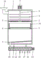
FIG. 1 is a schematic sectional view of the structure of the present invention;
FIG. 2 is a front view of the structure of the present invention;
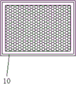
fig. 3 is a schematic top view of the local structure of the present invention.
In the figure: the device comprises a box body 1, a first partition plate 2, a second partition plate 3, a guide plate 4, a filter hole 5, a square hole 6, a first motor 7, a rotating rod 8, a crushing rod 9, a filter frame 10, a support rod 1, a conveying box 12, a second motor 13, a conveying rod 14, a conveying blade 15, a discharging pipe 16, a discharging pipe 17, a feeding pipe 18, a cover plate 19, an observation window 20, a buckle 21 and a clamping block 22.
Detailed Description
The technical solutions in the embodiments of the present invention will be described clearly and completely with reference to the accompanying drawings in the embodiments of the present invention, and it is obvious that the described embodiments are only some embodiments of the present invention, not all embodiments. Based on the embodiments in the present invention, all other embodiments obtained by a person skilled in the art without creative work belong to the protection scope of the present invention.
In the description of the present invention, it should be noted that the terms "upper", "lower", "inner", "outer", "front end", "rear end", "both ends", "one end", "the other end", and the like indicate orientations or positional relationships based on the orientations or positional relationships shown in the drawings, and are only for convenience of description and simplification of description, but do not indicate or imply that the device or element to be referred must have a specific orientation, be constructed in a specific orientation, and be operated, and thus, should not be construed as limiting the present invention. Furthermore, the terms "first" and "second" are used for descriptive purposes only and are not to be construed as indicating or implying relative importance.
In the description of the present invention, it is to be noted that, unless otherwise explicitly specified or limited, the terms "mounted", "provided", "connected", and the like are to be construed broadly, such as "connected", which may be fixedly connected, detachably connected, or integrally connected; can be mechanically or electrically connected; they may be connected directly or indirectly through intervening media, or they may be interconnected between two elements. The specific meaning of the above terms in the present invention can be understood in specific cases to those skilled in the art.
The utility model discloses a box 1, first baffle 2, second baffle 3, guide plate 4, filter the hole 5, square hole 6, first motor 7, bull stick 8, smash pole 9, filter frame 10, bracing piece 11, delivery box 12, second motor 13, delivery rod 14, conveyor blade 15, unloading pipe 16, arrange material pipe 17, inlet pipe 18, apron 19, observation window 20, buckle 21 and fixture block 22 part are the parts that universal standard spare or technical personnel in the field know, its structure and principle all can learn through the technical manual or learn through conventional experimental method for this technical personnel.
Referring to fig. 1-3, a metallurgical powder feeding device capable of feeding uniformly comprises a box body 1, wherein the bottom of the front side of the box body 1 is fixedly connected with an observation window 20, the front side of the observation window 20 is sprayed with scale marks, the storage amount of powder can be observed by arranging the observation window 20, the inner cavity of the box body 1 is fixedly connected with a first partition plate 2, a second partition plate 3 and a guide plate 4 from top to bottom in sequence, two sides of the top of the first partition plate 2 are respectively provided with a filtering hole 5, the crushed powder can be filtered and discharged by arranging the filtering holes 5, the top of the second partition plate 3 is provided with a square hole 6, the top of the box body 1 is fixedly connected with a first motor 7, the rotating shaft of the first motor 7 penetrates through the inner cavity of the box body 1 and is fixedly connected with a rotating rod 8, the bottom end of the rotating rod 8 is movably connected with the first partition plate 2, the surface of the rotating rod 8 is, by arranging the first motor 7, the rotating rod 8 and the smashing rods 9, the powder which is condensed can be uniformly scattered to prevent the powder from being condensed into blocks, the number of the smashing rods 9 is six, the smashing rods 9 are arranged at equal intervals, the top of the second partition plate 3 is provided with the filter frame 10, the powder with larger particles can be filtered by arranging the filter frame 10 to prevent the subsequent processing operation from being influenced, the filter frame 10 is positioned at the bottom of the filter hole 5, the two sides of the bottom of the box body 1 are both fixedly connected with the supporting rods 11, the bottom end of the supporting rod 11 is fixedly connected with the conveying box 12, the right side of the conveying box 12 is fixedly connected with the second motor 13, the rotating shaft of the second motor 13 penetrates through the inner cavity of the conveying box 12 and is fixedly connected with the conveying rod 14, the surface of the conveying rod 14 is fixedly connected with the conveying blades 15, and by arranging the conveying box 12, the second motor 13, the powder crushed and filtered can be conveyed, the left side of the bottom of the guide plate 4 is communicated with a discharging pipe 16, the bottom of the discharging pipe 16 penetrates through the bottom of the box body 1 and is communicated with the conveying box 12, the right side of the bottom of the conveying box 12 is communicated with a discharging pipe 17, the powder can be uniformly conveyed to an inner cavity of the powder box by arranging the discharging pipe 17, so that the subsequent metal forming effect is increased, the five discharging pipes 17 are arranged at equal intervals, the feeding pipe 18 is communicated with the top of the left side of the box body 1, the front side of the box body 1 is movably connected with a cover plate 19 through a hinge, a user can conveniently take and clean the filter frame 10 by arranging the cover plate 19, the two sides of the top of the front side of the cover plate 19 are movably connected with buckles 21, the two sides of the top of the front side of the box body 1 are fixedly connected with fixture blocks 22, the tops of the buckles 21 are clamped, the convenience is spacing fixed to apron 19, apron 19 is located the front side of filter frame 10, through box 1, first baffle 2, second baffle 3, guide plate 4, filter the hole 5, square hole 6, first motor 7, bull stick 8, smash pole 9, filter frame 10, bracing piece 11, delivery box 12, second motor 13, delivery rod 14, delivery vane 15, unloading pipe 16 and the cooperation of arranging material pipe 17, it is even and have the advantage of smashing and filtering capability to possess the feeding, current metallurgical powder feeding device has been solved, in the use, can't be to the even inner chamber of carrying to the powder box of metallurgical powder, thereby influence subsequent metal forming work, and because single structure, can't smash and filter the powder that condenses, the problem of feeding device suitability has been reduced.
When the powder crushing device is used, the discharging pipe 17 is communicated with an external powder box, metallurgical powder is put into an inner cavity of the box body 1 through the feeding pipe 18, the first motor 7 is controlled to operate through the external controller, the rotating shaft of the first motor 7 drives the rotating rod 8 and the crushing rod 9 to rotate, the crushing rod 9 crushes the powder to prevent the powder from being condensed, the crushed powder falls into an inner cavity of the filter frame 10 through the filter hole 5, the filter frame 10 filters the powder with larger particles, the filtered powder falls onto the top of the guide plate 4, the guide plate 4 guides the powder to an inner cavity of the discharging pipe 16, the discharging pipe 16 conveys the powder to an inner cavity of the conveying box 12, then the external controller controls the second motor 13 to operate, the rotating shaft of the second motor 13 drives the conveying rod 14 and the conveying blades 15 to rotate, the conveying blades 15 convey the powder, and the powder is uniformly discharged to the inner cavity of the powder box through the discharging pipe 17, and then the subsequent press forming work is started.
In summary, the following steps: this metallurgical powder feeding device that can evenly feed, through box 1, first baffle 2, second baffle 3, guide plate 4, filter hole 5, square hole 6, first motor 7, bull stick 8, smash pole 9, filter frame 10, bracing piece 11, delivery box 12, second motor 13, delivery rod 14, delivery vane 15, unloading pipe 16 and the cooperation of arranging material pipe 17, current metallurgical powder feeding device has been solved, in the use, can't be to the even inner chamber of carrying to the powder box of metallurgical powder, thereby influence subsequent metal forming work, and because single structure, can not smash and filter the powder that condenses, the problem of feeding device suitability has been reduced.
Although embodiments of the present invention have been shown and described, it will be appreciated by those skilled in the art that changes, modifications, substitutions and alterations can be made in these embodiments without departing from the principles and spirit of the invention, the scope of which is defined in the appended claims and their equivalents.
Claims (5)
1. The utility model provides a metallurgical powder feeding device that can even feed, includes box (1), its characterized in that: the inner cavity of the box body (1) is fixedly connected with a first baffle plate (2), a second baffle plate (3) and a guide plate (4) from top to bottom in sequence, filter holes (5) are formed in two sides of the top of the first baffle plate (2), a square hole (6) is formed in the top of the second baffle plate (3), a first motor (7) is fixedly connected to the top of the box body (1), a rotating shaft of the first motor (7) penetrates through the inner cavity of the box body (1) and is fixedly connected with a rotating rod (8), the bottom end of the rotating rod (8) is movably connected with the first baffle plate (2), a crushing rod (9) is fixedly connected to the surface of the rotating rod (8), a filter frame (10) is placed at the top of the second baffle plate (3), the filter frame (10) is located at the bottom of the filter holes (5), support rods (11) are fixedly connected to two sides of the bottom of the box body (1), the bottom fixedly connected with delivery box (12) of bracing piece (11), the right side fixedly connected with second motor (13) of delivery box (12), the pivot of second motor (13) runs through to the inner chamber and the fixedly connected with delivery rod (14) of delivery box (12), the fixed surface of delivery rod (14) is connected with and carries blade (15), the left side intercommunication of guide plate (4) bottom has unloading pipe (16), the bottom of unloading pipe (16) runs through to the bottom of box (1) and is linked together with delivery box (12), the right side intercommunication of delivery box (12) bottom has row material pipe (17), the left top intercommunication of box (1) has inlet pipe (18), there is apron (19) the front side of box (1) through hinge swing joint, apron (19) are located the front side of filter frame (10).
2. A metallurgical powder charging device of claim 1, wherein: the number of the crushing rods (9) is six, and the crushing rods (9) are arranged at equal intervals.
3. A metallurgical powder charging device of claim 1, wherein: the number of the discharge pipes (17) is five, and the discharge pipes (17) are arranged at equal intervals.
4. A metallurgical powder charging device of claim 1, wherein: the bottom fixedly connected with observation window (20) of box (1) front side, the front side of observation window (20) spouts and scribbles the scale mark.
5. A metallurgical powder charging device of claim 1, wherein: the improved box is characterized in that buckles (21) are movably connected to two sides of the top of the front side of the cover plate (19), clamping blocks (22) are fixedly connected to two sides of the top of the front side of the box body (1), and the top of each buckle (21) is connected with the corresponding clamping block (22) in a clamped mode.
Priority Applications (1)
| Application Number | Priority Date | Filing Date | Title |
|---|---|---|---|
| CN202021994158.2U CN213469566U (en) | 2020-09-14 | 2020-09-14 | Metallurgical powder feeding device capable of achieving uniform feeding |
Applications Claiming Priority (1)
| Application Number | Priority Date | Filing Date | Title |
|---|---|---|---|
| CN202021994158.2U CN213469566U (en) | 2020-09-14 | 2020-09-14 | Metallurgical powder feeding device capable of achieving uniform feeding |
Publications (1)
| Publication Number | Publication Date |
|---|---|
| CN213469566U true CN213469566U (en) | 2021-06-18 |
Family
ID=76419579
Family Applications (1)
| Application Number | Title | Priority Date | Filing Date |
|---|---|---|---|
| CN202021994158.2U Expired - Fee Related CN213469566U (en) | 2020-09-14 | 2020-09-14 | Metallurgical powder feeding device capable of achieving uniform feeding |
Country Status (1)
| Country | Link |
|---|---|
| CN (1) | CN213469566U (en) |
Cited By (1)
| Publication number | Priority date | Publication date | Assignee | Title |
|---|---|---|---|---|
| CN114378310A (en) * | 2021-12-30 | 2022-04-22 | 浙江闪铸三维科技有限公司 | Powder 3D printer |
-
2020
- 2020-09-14 CN CN202021994158.2U patent/CN213469566U/en not_active Expired - Fee Related
Cited By (1)
| Publication number | Priority date | Publication date | Assignee | Title |
|---|---|---|---|---|
| CN114378310A (en) * | 2021-12-30 | 2022-04-22 | 浙江闪铸三维科技有限公司 | Powder 3D printer |
Similar Documents
| Publication | Publication Date | Title |
|---|---|---|
| CN213469566U (en) | Metallurgical powder feeding device capable of achieving uniform feeding | |
| CN208050930U (en) | Metal powder crush and grind all-in-one machine | |
| CN213792839U (en) | Rice processing is with screening miscellaneous device that goes | |
| CN210675422U (en) | Equipment for extracting odor removal substances from plants | |
| CN210753621U (en) | Multistage screening flotation comprehensive recovery system for low-grade gold ore | |
| CN207857418U (en) | Brush device for clearing up sintering backing plate | |
| CN216125809U (en) | Integral crankshaft machining waste pretreatment equipment | |
| CN211101338U (en) | Thread rolling machine convenient to retrieve coolant liquid | |
| CN212371102U (en) | Tectorial membrane sand used sand regenerating unit | |
| CN112475306A (en) | Multifunctional gas atomization metal powder bed | |
| CN209156431U (en) | Waste residue collection device in a kind of preparation of casting | |
| CN209348759U (en) | A kind of disintegrating apparatus with dust collection function | |
| CN213493965U (en) | Scrap iron retrieves and uses sorting device | |
| CN212884901U (en) | Molten aluminum smelting slag remover conveying device | |
| CN217939615U (en) | Dust device is used in transportation of iron and steel smelting iron powder waste material | |
| CN221815818U (en) | A compounding system for hydrometallurgy production | |
| CN210619091U (en) | Automatic kiln material receiving device for lithium titanate production | |
| CN219309005U (en) | Workshop waste recycling equipment | |
| CN216758536U (en) | Automatic material collecting device for plasma cutting machine | |
| CN215694350U (en) | Broken dust collector of steel waste | |
| CN220144325U (en) | Waste recovery device for stainless steel strip production | |
| CN217830156U (en) | A rubbing crusher for brickmaking processing | |
| CN215050455U (en) | Scrap steel smelting device for resource regeneration | |
| CN218954593U (en) | Mechanical lubricating liquid recovery device | |
| CN221108380U (en) | Raw material crushing device for steelmaking furnace burden production |
Legal Events
| Date | Code | Title | Description |
|---|---|---|---|
| GR01 | Patent grant | ||
| GR01 | Patent grant | ||
| CF01 | Termination of patent right due to non-payment of annual fee | ||
| CF01 | Termination of patent right due to non-payment of annual fee |
Granted publication date: 20210618 Termination date: 20210914 |